Table of Contents
Advertisement
Advertisement
Table of Contents

Related Manuals for Santec TSL Series


Summary of Contents for Santec TSL Series
- Page 1 Artisan Technology Group is your source for quality new and certified-used/pre-owned equipment SERVICE CENTER REPAIRS WE BUY USED EQUIPMENT • FAST SHIPPING AND DELIVERY Experienced engineers and technicians on staff Sell your excess, underutilized, and idle used equipment at our full-service, in-house repair center We also offer credit for buy-backs and trade-ins •...
- Page 2 TUNABLE LD LIGHT SOURCE TSL-210 Operation Manual Artisan Technology Group - Quality Instrumentation ... Guaranteed | (888) 88-SOURCE | www.artisantg.com...
- Page 3 TSL-210 OPERATION MANUAL Notes to Users 1) Copyright 1997 Santec Photonics Laboratories. All rights reserved. No part of this Operation Manual may be reproduced or transmitted in any form or by any means, electronic or mechanical, for any purpose, without the prior written permission of Santec.
- Page 4 TUNABLE LD LIGHT SOURCE TSL-210 Introduction Thank you very much for your having purchased our product, Tunable LD Light Source TSL Series. This Operation Manual contains information necessary for the operation of TSL-210, and it is intended for those with sufficient knowledge enough to of laser danger and its safe control. Before operating TSL-210, you should first read thoroughly through this Operation Manual and become familiar to its contents.
- Page 5 TSL-210 OPERATION MANUAL Constitution of this Operation Manual and How to Read it This Operation Manual should be read before operating TSL-210. This Operation Manual consists of 15 chapters, and the contents of each are as follows : Chapters 1 through 8 describe the outline of the product, notes on safety, and installation of the product.
- Page 6 TUNABLE LD LIGHT SOURCE TSL-210 Marking on the instrument This indicates that caution is required. Please refer to the operation manual. This indicates there is a danger due to laser radiation. Do not look directly at the laser beam or look at the beam by eye through any optical instrument.
- Page 7 TSL-210 OPERATION MANUAL Explanation of Terms The meanings of the following terms used in this Operation Manual are defined as below : (1) Meaning This indicates pressing DANGER, and if it DANGER!! DANGER is not avoided, personnel death or serious injury results, therefore, it is the most emphasized special information.
-
Page 8: Table Of Contents
TUNABLE LD LIGHT SOURCE TSL-210 Table of Contents Introduction Constitution of this Operation Manual and How to Read it Explanation of Terms 1. Outline of Product 2. Configuration 3. Specifications 4. Principle of Operation 5. Safety Notes and Safety Devices 6. - Page 9 TSL-210 OPERATION MANUAL 9. Fundamental Operation How to Turn ON 9-1-A Turning ON / Setting RS-232C Delimiter 9-1-B Optical Fiber Connection 9-1-C Cleaning the Optical Connector 9-1-D Changing LD Current / Changing Unit of Optical Power How to Use Rotary Encoder Setting Wavelength 9-3-A Minimum digit setting Setting Optical Output Power (APC function)
- Page 10 TUNABLE LD LIGHT SOURCE TSL-210 Communication 10-1 • 10-1.GP-IB 10-1 10-1-A Outline 10-1 10-1-B How to Use 10-1 10-1-C GP-IB Function 10-2 10-1-D GP-IB of TSL-210 10-2 10-1-E GP-IB Connector 10-3 • 10-2.RS-232C 10-4 10-2-A Outline 10-4 10-2-B How to Use 10-4 10-2-C RS-232C of TSL-210 10-4...
- Page 11 TSL-210 OPERATION MANUAL Artisan Technology Group - Quality Instrumentation ... Guaranteed | (888) 88-SOURCE | www.artisantg.com...
-
Page 12: Outline Of Product
(optical band pass filter, AWG, fiber grating, etc.), EDFA, and DWDM. Santec designed the TSL-210 to meet this need with a unit that has precise wavelength tuning accuracy, excellent wavelength and power stability, and high optical output power. - Page 13 TSL-210 OPERATION MANUAL Artisan Technology Group - Quality Instrumentation ... Guaranteed | (888) 88-SOURCE | www.artisantg.com...
-
Page 14: Configuration
TUNABLE LD LIGHT SOURCE TSL-210 Configuration s a n te c WA VE LE NG TH TE MP .ER RO R CU RR .LI PO WE R MI T dB m mW /dB m CO H SH IFT OP TIO N WA VE LE AC C NG TH... - Page 15 TSL-210 OPERATION MANUAL Artisan Technology Group - Quality Instrumentation ... Guaranteed | (888) 88-SOURCE | www.artisantg.com...
-
Page 16: Specifications
TUNABLE LD LIGHT SOURCE TSL-210 Specifications Specification parameter Unit Min. Spec. Max. Note Wavelength Tuning range 1530 1610 Minimum tuning Resolution 0.01 <0.001nm When using fine tuning Accuracy Number of times of measurement n=50, Measured at center Repeatability 0.05 wavelength Stability 0.01 1 hour, Measured at center wavelength... - Page 17 TSL-210 OPERATION MANUAL Optiona List parameter Unit Min. Spec. Max. Note Wavelength Tuning range 1260 1640 Maximum tuning range: >80nm (choose from 1260~1640nm) Power Maximum output power High power output Built in attenuator Resolution 0.04dB(Typ.) Built in tracking filter -3dB bandwidth: 3nm, Resolution 0.24nm(Typ.)*1 Interface Optical connector SLOW axis, Polarization extinction ratio>17dB,Polarization...
-
Page 18: Principle Of Operation
TUNABLE LD LIGHT SOURCE TSL-210 Principle of Operation Mirror Grating LD L 2 SPC Connector Temperature controlled chamber •Rotating table •Direct operating table* • Temperature control GP-IB • Current control CPU Control • Diffraction grating angle control • Others RS-232C FIG.1 Structure diagram of TSL-210 The structure of the TSL-210 is shown in FIG 1. - Page 19 TSL-210 OPERATION MANUAL Artisan Technology Group - Quality Instrumentation ... Guaranteed | (888) 88-SOURCE | www.artisantg.com...
-
Page 20: Safety Notes And Safety Devices
(shown in the figure below). Do not open the instrument case. The laser beam used in this product is harmful to the eyes. There are no user servicable parts. Please refer all maintenance and repair to a Santec engineer. Protective shutter Optical output CAUTION When the unit is not in operation, be sure to disconnect the power cord. - Page 21 TSL-210 OPERATION MANUAL Artisan Technology Group - Quality Instrumentation ... Guaranteed | (888) 88-SOURCE | www.artisantg.com...
-
Page 22: Installation
TUNABLE LD LIGHT SOURCE TSL-210 Installation Pay attention to the following guidelines for safe, trouble-free operation. This product is a high-precision device: Do not place in direct sunlight • Do not place under high temperature and high humidity. • Do not place in an environment with dust, dirt, salt, or corrosive gas. •... - Page 23 TSL-210 OPERATION MANUAL Artisan Technology Group - Quality Instrumentation ... Guaranteed | (888) 88-SOURCE | www.artisantg.com...
-
Page 24: Descriptions Of Panel Equipment
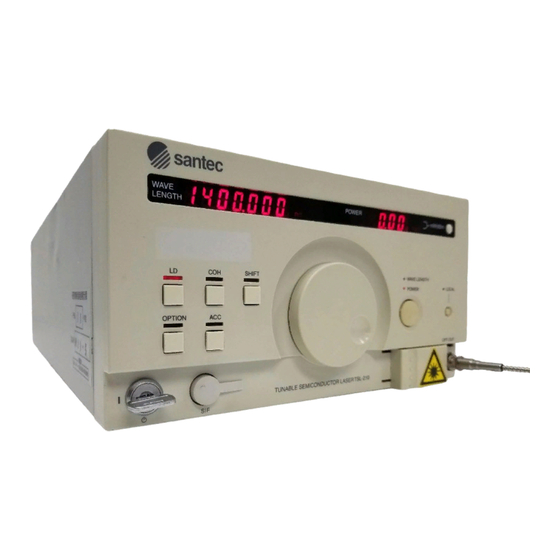
TUNABLE LD LIGHT SOURCE TSL-210 Descriptions of Panel Equipment 7-1 Front Panel santec WAVE TEMP.ERROR POWER mW/dBm LENGTH CURR.LIMIT SHIFT WAVE LENGTH POWER LOCAL OPTION OPT.OUT TUNABLE SEMICONDUCTOR LASER TSL-210 (1) Wavelength / fine tuning display panel This displays the currently set wavelength and the wavelength at wavelength calibration. When fine tuning is turned ON, it displays the currently set control amount. - Page 25 TSL-210 OPERATION MANUAL (7) LD drive LED / ATT Mode (Option) 1. This LED indicates that current is injected into LD. 2. When this LED flickers, it shows that LD drive is in the mode not to feed back the fluctua- tion of optical output power.
- Page 26 TUNABLE LD LIGHT SOURCE TSL-210 (16) ACC Mode Key/RS-232C Delimiter Adjustment/ATT Mode Switching (Option) 1. The TSL-210 can be operated in either Automatic Power Control (APC) or Automatic Cur- rent Control (ACC) mode. When the power switch is first turned on, the unit will be in the APC mode.
- Page 27 TSL-210 OPERATION MANUAL (23) Main switch This toggles ON/OFF the power source. (I=ON, O=OFF) Switch this by use of the power key. (24) SIF (serial interface) connector This is a connector for RS-232C communication. It is used in numeric key operation or table operation by external devices such as Zaurus or so.
-
Page 28: Rear Panel
TUNABLE LD LIGHT SOURCE TSL-210 7-2 Rear Panel (1) GP-IB connector (Refer to 10-5 GP-IB) (2) AIF (analog interface) connector Terminal for fine tuning control and low frequency modulation from external. (3) Option Panel Input terminal for level adjustment knob of variable coherence control and RF modulation of options. - Page 29 TSL-210 OPERATION MANUAL (5) Power voltage change switch and fuse box lid When it is necessary to change the power voltage setting, open the lid, set the internal rotary switch to the correct voltage and replace the fuses with the correct rating. Replace the lid. Use a surge resistant fuse.
- Page 30 TUNABLE LD LIGHT SOURCE TSL-210 6) Power source socket Use the attached power source cable. Europe Only U.K. Only Japan Only Japan, USA, Canada and other countries (7) Slit Slit for heat dissipation. A fan is arranged inside of the slit. Arrange space of over 5cm to allow for proper ventilation.
-
Page 31: Bottom Panel
TSL-210 OPERATION MANUAL 7-3 Bottom Panel (1) Vent This is a heat release vent. The vent intakes air for cooling. Do not cover the vent or place any heat sources near by; the instrument may retain heat or malfunction. (2) Rubber feet The rubber feet support the instrument and absorb external vibration. -
Page 32: Functions Of This Unit
TUNABLE LD LIGHT SOURCE TSL-210 Functions of This Unit 8-1. Wide-band Wavelength Tuning TSL-210 The use of a diffraction grating as external mirror in the design controls the loss to wavelength within the external cavity by controlling the angle of diffraction grating in a high-precision manner, and also allows for the tuning of an oscillated wavelength over a wide range. -
Page 33: Ld Injection Current, Ambient Temperature Control
TSL-210 OPERATION MANUAL 8-3. LD Injection Current, Ambient Temperature Control Function To keep a stable oscillating condition of the semiconductor laser, the TSL-210 precisely controls injection current and adjusts for ambient temperature changes. The circuit that supplies the LD injection current provides a stable, constant current and also has a protection circuit so that the LD does not become damaged. -
Page 34: Fine Tuning Function
Reference light source Frequency Control circuit Frequency discriminator PI control, etc. (Example 2) Output (Example) • Etharon module OWL-10 • Cell etc. Made by Santec Control circuit Artisan Technology Group - Quality Instrumentation ... Guaranteed | (888) 88-SOURCE | www.artisantg.com... - Page 35 TSL-210 OPERATION MANUAL Artisan Technology Group - Quality Instrumentation ... Guaranteed | (888) 88-SOURCE | www.artisantg.com...
-
Page 36: Fundamental Operation
TUNABLE LD LIGHT SOURCE TSL-210 Fundamental Operation 9-1 How to Turn ON DANGER!! Before turning ON the unit, make sure that the protective shutter is closed. Laser beam, if it comes into your eye, may cause injury in your sense of sight. 9-1-A Turning ON/Setting RS-232C Delimiter Make sure the power is supplied by the attached power cord. - Page 37 TSL-210 OPERATION MANUAL 3) RS-232C delimiter is displayed. WAVE TEMP.ERROR POWER mW/dBm LENGTH CURR.LIMIT WAVE TEMP.ERROR POWER mW/dBm LENGTH CURR.LIMIT WAVE TEMP.ERROR POWER mW/dBm LENGTH CURR.LIMIT RS-232C delimiter can be changed by turning on power while holding OPTION or APC key. The delimiter setting is kept effective even though unit is OFF.
-
Page 38: 9-1-B Optical Fiber Connection
TUNABLE LD LIGHT SOURCE TSL-210 9-1-B Optical Fiber Connection Open the protective cover and connect the optical fiber. CAUTION Before connecting optical fiber, clean the end surface of optical fiber. Dirty surface with dust may cause loss. 9-1-C Cleaning the Optical Connector Connection of an optical fiber with dust and dirt on the end of the optical connector of the TSL-210 will cause loss of optical input, therefore, clean the connector periodically. - Page 39 TSL-210 OPERATION MANUAL 9-1-D Changing LD Current/Changing Unit of Optical Output Power DANGER!! Before turning ON the unit, make sure that the protective shutter is closed or the optical fiber is connected. Keep the optical output terminal away from your eyes. Laser beam, if it comes into your eye, may cause injury in your sense of sight.
-
Page 40: How To Use Rotary Encoder
TUNABLE LD LIGHT SOURCE TSL-210 9-2 How to Use Rotary Encoder This product does not come equipped with a numeric key to input numeric values. A rotary encoder is used to set wavelength, and to set optical output power (in APC mode only), to fine tune, to calibrate wavelength, to set GP-IB address, and to set the minimum increment/ decrement resolution of the encoder. -
Page 41: Setting Wavelength
TSL-210 OPERATION MANUAL 9-3 Setting Wavelength Make sure that the rotary encoder wavelength setting LED is lit. WAVE LENGTH POWER When the LED is not lit, turn the rotary encoder change key to the wavelength side. WAVE LENGTH POWER TUNABLE SEMICONDUCTOR LASER TSL-210 After making sure the wavelength setting LED is lit, set the wavelength by the rotary encoder. -
Page 42: 9-3-A Minimum Digit Setting
TUNABLE LD LIGHT SOURCE TSL-210 9-3-A. Minimum digit setting As for wavelength setting, minimum tuning step can be selected by the following operation. Please push shift key. (This key toggles the sift function ON/OFF) When the key is pressed, SHIFT LED is lit, and the next key entry is ready. SHIFT SHIFT Press SHIFT key. -
Page 43: Setting Optical Output Power (Apc Function)
TSL-210 OPERATION MANUAL 9-4 Setting Optical Output Power (APC function) 9-4-A. Setting Optical Output Power (APC function) It is necessary to operate the machine in APC mode to set optical output power. Optical output power cannot be set in ACC mode. Be sure that the mode is in APC. (ACC indicator is not lit. If ACC indicator is lit, press ACC again thereby activating APC.) WAVE LENGTH POWER... -
Page 44: 9-4-B Acc Function
TUNABLE LD LIGHT SOURCE TSL-210 Set the optical output power by the rotary encoder. And as for entry of optical output power, entry is available by either "mW" or "dBm". TUNABLE SEMICONDUCTOR LASER TSL-210 9-4-B. ACC Function This product operates in two modes, APC (automatic power control) mode and ACC (auto- matic current control) mode. -
Page 45: 9-4-C Changeover Of Optical Output Power Unit
TSL-210 OPERATION MANUAL 9-4-C. Changeover of Optical Output Power Unit NOTE Changeover of optical output power Unit The display of optical output power unit may be changed between “mW” or “dBm”. Press the optical output power unit change key. When the key is pressed, unit display is changed. -
Page 46: 9-5-A Internal Control
TUNABLE LD LIGHT SOURCE TSL-210 9-5-A. Internal Control Press the option key. (This key toggles the fine tuning control ON/OFF.) When this key is pressed, the option LED is lit. Wavelength display changes into fine tuning display. The initial value is 0.00. Make sure that the rotary encoder wavelength setting LED is lit. WAVE LENGTH OPTION OPTION... -
Page 47: 9-5-B External Control
TSL-210 OPERATION MANUAL 9-5-B. External Control The external control of fine tuning controls the driver circuit to drive PZT (piezo) by external input voltage. Input ±3V voltage from pin No.1 (SIGNAL) and pin No.2 (GND) of the AIF (analog interface) connector on the rear panel. Impressing voltages other than the above causes voltage limit in the built-in driver circuit to be reached, and control is not available. -
Page 48: Coherence Control
TUNABLE LD LIGHT SOURCE TSL-210 9-6 Coherence Control Press the coherence control key. (This key toggles ON/OFF of the coherence control.) SHIFT SHIFT When the key is pressed, the coherence control LED is lit, to show that the coherence control is ON. -
Page 49: Low Freauency Modulation
TSL-210 OPERATION MANUAL 9-7 Low Frequency Modulation CAUTION Do not apply voltage in excess of input level amount. When not using Low Fre- quency modulation, be sure to cap the terminals, so that deterioration of the termi- nals does not occur. In the low frequency modulation, the current driver to drive LD is controlled by external input voltage. -
Page 50: Wavelength Calibration
TUNABLE LD LIGHT SOURCE TSL-210 NOTE TSL-210 has the current control mode and the power control mode. In either case, feed back loop control to stabilize optical output power inside is conducted. In the case to use low frequency modulation, if feed back loop is not removed, external input voltage is handled as fluctuation, so preferable modulation is not available. - Page 51 TSL-210 OPERATION MANUAL POWER mW/dBm mW/dBm Press mW/dBm key. Setting here. After completion of the setting routine, press the wavelength calibration key once again. When the key is pressed, set value internal writing condition starts. The symbol "- (minus)" in the display changes to the symbol "_ (under bar)."...
-
Page 52: Setting Gp-Ib Address And Delimiter
TUNABLE LD LIGHT SOURCE TSL-210 9-9 Setting GP-IB Address and Delimiter After setting, press GP-IB address delimiter key again. SHIFT SHIFT Move to delimiter setting WAVE LENGTH POWER LOCAL Change delimiter Move in to delimiter setting mode after address setting. Delimiter has CR, LF, CR+LF and EOI which doesn’t have any character. -
Page 53: Turning Off
TSL-210 OPERATION MANUAL 9-10 Turning OFF 9-10-A Turning OFF Injection Current (LD drive LED lights or flickers) Press the LD drive key. When the key is pressed, the injection current value will reduce to zero, and the value of the optical output power display panel changes according to current. OPTION OPTION Press LD drive key. -
Page 54: 9-10-B Turning The Power Off
TUNABLE LD LIGHT SOURCE TSL-210 9-10-B. Turning the Power OFF Make sure that the LD drive LED is off, then turn the power key 90 degrees to the left to turn off the power. Turn the power key 90 degrees to the left. 9-19 Artisan Technology Group - Quality Instrumentation ... - Page 55 TSL-210 OPERATION MANUAL 9-20 Artisan Technology Group - Quality Instrumentation ... Guaranteed | (888) 88-SOURCE | www.artisantg.com...
-
Page 56: Communication
TUNABLE LD LIGHT SOURCE TSL-210 Communication CAUTION Before connecting or disconnecting the communication connector, be sure to turn OFF this product. Otherwise, a fault may result. The TSL-210 supports three different communication protocols, RS-232C and GP-IB, for external communication with the TSL-210. In addition, LabVIEW software drivers are avail- able. -
Page 57: 10-1-C Gp-Ib Function
TSL-210 OPERATION MANUAL 10-1-C GP-IB Function GP-IB has 10 kinds of interface functions, each of which has its grade that is called it's sub set. A "O" after the symbol of each function shows that support is not made, and each numeric value represents grade. -
Page 58: 10-1-E Gp-Ib Connector
TUNABLE LD LIGHT SOURCE TSL-210 4. Command, Data, Delimiter Command consists of 2 alphabetical letters, irrespective of upper or lower case. When inputting data, input numeric value data following command. Command, delimiter of command, and data are CL+LF (0D0A). When a wrong command is received, the TSL-210 outputs "NR"... -
Page 59: Rs-232C
TSL-210 OPERATION MANUAL 10-2 RS-232C 10-2-A Outline RS-232C was originally designed to connect a data terminal device and a modem; it requires a power source larger than the 5V power source which is used in current personal computers and also a minus power source. However, since most personal computers are now equipped with RS-232C, which requires only 3 lines, a user can easily interface the TSL-210 with a PC. -
Page 60: 10-2-D Sif Connector (Rs-232C)
TUNABLE LD LIGHT SOURCE TSL-210 2. Command, Data, Delimiter Command consists of 2 alphabetical letters, irrespective of upper or lower case. When input- ting data, input numeric value data following command. When it receives a correct command, it echoes back 2 letters of command irrespective of data presence or absence. But when a wrong command is received, TSL-210 outputs "NR". -
Page 61: 10-2-E Control Pad
TSL-210 OPERATION MANUAL D sub 9 pin connector Signal SIF Connector Data Carrier Detect Signal Receive Data Transit Data Data Terminal Ready Signal Ground SG(GND) 6.4V Data Set Ready Request To Send RRDX Clear To Send RTDX Ring Indicate D sub 25 pin connector Signal Frame Ground Transit Data... -
Page 62: 10-3.Communication Control
TUNABLE LD LIGHT SOURCE TSL-210 10-3 Communication Control 10-3-A. Commands There are commands to change internal conditions and commands to change external condi- tions. When changing output data, send a command consisting of two alpha characters. When changing control data, send numeric data following a command of two alpha characters. In this case, the output data is changed at the same instant as the control data. - Page 63 TSL-210 OPERATION MANUAL List of Commands Command Contents Message Type Parameter 1. Sets output variable to current. 1. CU 2. Sets injection current to numeric data added to 2. CU X X X . X X command. Unit is mA. 1.
- Page 64 *2 When supplying or intercepting current to LD, it takes time to set the internal processing. The status changes when the processing finishes. *3 This command can be set only when in ACC or ATT manual mode. Key Index santec WAVE TEMP.ERROR POWER...
-
Page 65: 10-3-B Taking Out Data
TSL-210 OPERATION MANUAL 10-3-B. Taking Out Data In the TSL-210, the method to retrieve data differs between GP-IB and RS-232C. Explana- tions on how to take data out per each communication protocol are outlined below: 1. GP-IB When a command is executed, the output data changes. At the next data request, data is auto- matically selected and output. -
Page 66: 10-3-C Status
TUNABLE LD LIGHT SOURCE TSL-210 10-3-C. Status The status of TSL is represented by minus sign and 6-digit 0 ~ 7 numbers. Status can be taken out by communication SU command, and each status may be confirmed by the display panel and LED on the front panel. -
Page 67: 10-4.Sample Program
TSL-210 OPERATION MANUAL 10-4 Sample Program This sample program is written in N88BASIC on NEC-9800 series. This program steps wave- length from 1500 nm up to 1580 nm, in unit of 0.1 nm, and reads the optical output power at each wavelength. -
Page 68: 10-4-B Gp-Ib Sample Program
TUNABLE LD LIGHT SOURCE TSL-210 10-4-B. GP-IB Sample Program [ Description ] 1000 ISET IFC Sends out "IFC" signal. 1010 ISET REN Sets "REN" signal to TRUE. 1020 PRINT @1; "WA1500" Sets wavelength to "1500nm". 1030 GOSUB *MOTOR.CHK Checks whether wavelength tuning is ON or not. 1040 FOR SW=1500 TO 1580 STEP .1 Varies from 1500nm to 1580nm by 0.1nm, and... - Page 69 TSL-210 OPERATION MANUAL 10-14 Artisan Technology Group - Quality Instrumentation ... Guaranteed | (888) 88-SOURCE | www.artisantg.com...
-
Page 70: Maintenance
TUNABLE LD LIGHT SOURCE TSL-210 Maintenance 11-1. Daily Maintenance Connection of an optical fiber with dust and dirt on the end of the optical connector of the TSL- 210 will cause loss of optical input, therefore, clean the connector periodically. The optical adapter may be removed by removing the screws as shown in the figure below. - Page 71 TSL-210 OPERATION MANUAL 11-3. Replacing the Fuse Use the suitable fuse for power source voltage. * Use the anti-surge type fuse. 11-4. Inspection and calibration The warranty for TSL-210 is one year. We recommend to have TSL-210 inspected and calibrated regularly (1 year). For inspection or calibration, please contact our sales team.
-
Page 72: Long-Term Storage
TUNABLE LD LIGHT SOURCE TSL-210 Long-term Storage Here are some instructions on long-term storage of this product. NOTE Recycling the packing materials will help repacakge this product, so keep the packing materials. Notes before Storage 1) Wipe away dust, dirt, finger print, other stain on this product. 2) Use the packing materials for packing. - Page 73 TSL-210 OPERATION MANUAL 12-2 Artisan Technology Group - Quality Instrumentation ... Guaranteed | (888) 88-SOURCE | www.artisantg.com...
- Page 74 TUNABLE LD LIGHT SOURCE TSL-210 Option 13-1 High Frequency Modulation CAUTION Do not apply voltage which is outside the input level. When not using high fre- quency modulation, terminate the high frequency modulation port. Otherwise optical output power may become unstable. Input the high modulation signal only while the current is being injected into the LD.
- Page 75 TSL-210 OPERATION MANUAL Rear Panel Layout • High Frequency Modulation Input Terminal (SMA) 13-2 Control Pad (CP-10) TSL-210 is designed with a simple and easy to use front panel interface. It has minimal func- tion keys and does not have a numeric keypad for direct wavelength and power setting input. The CP-10 control pad addresses both of these issues, and provides full support of all functions in a compact, handheld design.
- Page 76 TUNABLE LD LIGHT SOURCE TSL-210 13-3 Built-in Attenuator 13-3-A Introduction By adopting an external cavity structure the product has maintained various semiconductor laser features. In particular this structure make it possible to tune the wavelength of the laser light. However, the optical output power is controlled by tuning the LD injection current. This causes a change in the optical path length in the LD that can consequently cause an opti- cal wavelength shift or cause difficulty in maintaining adequate SSR (side-mode suppression ratio).
- Page 77 TSL-210 OPERATION MANUAL 13-3-C Control Method ATT option is not designed to frequently control the attenuation level. Both manual control and automatic control are available and these modes can be set using the external communica- tion port. 1) Manual Control Manual control allows the ATT number to be set using the external communication port.
- Page 78 TUNABLE LD LIGHT SOURCE TSL-210 3) Automatic control (ATE, AF) Automatic control is available via key operation from the front panel or via mode switching through the external communication port. In APC mode, ATT can be automatically set depend- ing on the change of optical output power. When it is in Automatic Control mode the LED above the LD key is lit and in the case of control by external communication a 2 is added to the 4th digit of the status display.
- Page 79 TSL-210 OPERATION MANUAL 13-6 Artisan Technology Group - Quality Instrumentation ... Guaranteed | (888) 88-SOURCE | www.artisantg.com...
-
Page 80: Troubleshooting
TUNABLE LD LIGHT SOURCE TSL-210 Troubleshooting Table of Troubleshooting Fault condition Cause Action No power Cord is unconnected. Connect cord properly. No fuse or fuse is blown out Open the fuse box lid and replace fuse (see section 7) Power voltage is incorrect Open the fuse box lid and rotate power voltage change switch to proper voltage (see section 7) No light output... - Page 81 Santec Photonics Laboratories. Our telephone number and facsimile number are shown below.
- Page 82 Artisan Technology Group is your source for quality new and certified-used/pre-owned equipment SERVICE CENTER REPAIRS WE BUY USED EQUIPMENT • FAST SHIPPING AND DELIVERY Experienced engineers and technicians on staff Sell your excess, underutilized, and idle used equipment at our full-service, in-house repair center We also offer credit for buy-backs and trade-ins •...
Need help?
Do you have a question about the TSL Series and is the answer not in the manual?
Questions and answers