Table of Contents
Advertisement
Quick Links
Advertisement
Table of Contents
Troubleshooting

Subscribe to Our Youtube Channel
Related Manuals for Nidec MCE iControl


Summary of Contents for Nidec MCE iControl
- Page 1 Motion Control Engineering 11380 White Rock Road Rancho Cordova, CA 95742 voice 916 463 9200 fax 916 463 9201 https://acim.nidec.com/elevators/motion-control-engineering User Guide, iControl with DC Drive, Release 3 & 4 ATTENTION! Manual # 42-02-7223, Rev C1, April 2023...
- Page 2 Copyright This document is owned and copyrighted by Motion Control Engineering. All Rights Reserved. Upon request by Motion Control Engineering, this document must be returned to Motion Control Engineering. ©Motion Control Engineering, 2022. Trademarks All trademarks or registered product names appearing in this document are the exclusive property of the respective owners.
- Page 3 End User License Agreement This End User License Agreement (“Agreement”) grants you the right to use the software contained in this product (the “Software”) subject to the following restrictions: You may not: (i) copy the Software, except for archive purposes consistent with your standard archive procedures; (ii) trans- fer the Software to a third party apart from the entire product;...
-
Page 4: Safety And Other Symbol Meanings
Important Precautions and Useful Information This preface contains information that will help you understand and safely maintain MCE equipment. We strongly recommend you review this preface and read this manual before installing, adjusting, or maintaining Motion Control Engineering equipment. This preface dis- cusses: •... -
Page 5: Environmental Considerations
resistance to ground by using the shortest possible routing. See National Electrical Code Article 250 or the applicable local electrical code. Before applying power to the controller, physically check all the power resistors and other components located in the resistor cabinet and inside the controller. Components loosened during shipment may cause damage. - Page 6 42-02-7223 C1...
-
Page 7: Table Of Contents
Contents Safety and Other Symbol Meanings ........1-iv Safety Precautions . - Page 8 Access Locks and Contacts ..........2-16 Rope Gripper Wiring .
- Page 9 Auto Tune Procedure (Quattro DC Drive) ........2-50 Drive Response Adjustments (Quattro DC Drive) .
- Page 10 Empty Car Tests ............3-13 Section 4.
- Page 11 Brake Parameter Adjustments ..........4-27 Calibrating the Floor Offsets .
- Page 12 Section 5. System Options About System Options ..........5-1 iCentral - Central Dispatcher .
- Page 13 iBox Configuration > Load ..........6-86 Replacing Circuit Boards .
- Page 14 LCD Status Display ............7-11 System Control Switches .
- Page 15 Bootrom Recovery via OBD ..........8-50 Section 9.
- Page 16 x Manual # 42-02-7223 C1...
-
Page 17: Icontrol Overview
iControl Description iControl Overview This section provides: • A general description of the iControl system, page 1-2 • System interconnect diagrams, page 1-4 • Installation Specifications, page 1-7 42-02-7223 C1 1-1... -
Page 18: General Description
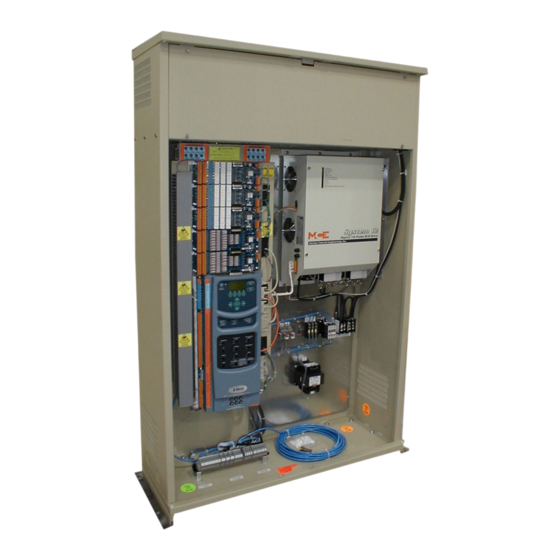
iControl Description General Description Figure 1.1 Cabinet Layout (typical) Resistor cabinet iBox System 12 SCR drive (Note: Quattro DC Drive is supplied in a separate cabinet) iPower box Standard cabinet dimensions: Height = 62 inches (157.5 cm) Width = 42 inches (107 cm) Depth = 16 inches (41 cm) Measurements are approximate Component Assemblies... -
Page 19: Group Dispatching
iControl DC General Description • Load weighers (optional) • Rope Tension (LW-EMCO) • Isolated Platform (LW-MCEIP) • Cross Head Deflection (K-Tech International) Figure 1.2 Single Car Component Assembly Illustrations iDC Controller iLink cartop box iLand Compact landing system Group Dispatching For multiple car installations requiring centralized dispatching and parking control: •... -
Page 20: System Interconnect Diagrams
iControl Description System Interconnect Diagrams It can be helpful to have a general understanding of the way the entire iControl system is inter- connected. • System Interconnection: Basic car control and dispatcher interconnections. • iControl Interconnection: More detail for car controller interconnections. •... - Page 21 iControl DC System Interconnect Diagrams Figure 1.4 Car Control Interconnection iCONTROL Field Outputs Outputs Discrete Hall Calls (if not Serial Hall Call) Field Inputs Inputs Fixture Data Serial Fixtures Drive EQ String Earthquake iBox Safeties Limits Cartop Motor Module Emergency Brake Rope Gripper Brake Module...
- Page 22 iControl Description Figure 1.6 Central Dispatcher (iCentral) Interconnection iMonitor or iReport DISPATCHER Monitor iView Switch To Cars Keyboard LAN: iView, iMonitor, iReport connectivity. iCue General Field Inputs to Dispatcher SYSTEM Hall Calls To Cars SYSTEM: Hall calls, Parking, Serial Special operating modes Driver Serial to Ethernet...
-
Page 23: Installation Specifications
iControl DC Installation Specifications Installation Specifications This section contains specifications pertinent to installing the controller. Table 1.1 Topic Description Controller dimensions NEMA 1: (floor mount) Height = 62 inches (157.5 cm) Width = 42 inches (107 cm) Depth = 16 inches (41 cm) iCentral cabinet Height = 72 inches (183 cm) (floor mount) - Page 24 iControl Description 1-8 Manual # 42-02-7223 C1...
-
Page 25: Section 2. Construction Mode
Construction Mode In This Section This section provides the information you need to install iControl and get the elevator running in Construction Mode: • Machine Room Preparation (see page 2-4). • Controller Cabinet Installation (see page 2-6). • Equipment Grounding (see page 2-6). •... -
Page 26: Before You Begin
Construction Mode Before You Begin Review the warnings and information in this section. Danger This equipment contains voltages up to 1000V, rotating motor parts, and driven machinery that can cause serious or fatal injury. Only qualified personnel who are familiar with this manual and driven machinery should attempt to start up or troubleshoot this equipment. - Page 27 iControl DC In This Section Required Connections The following connections are necessary to run the car on Con- struction Mode: • Motor, Brake, and Drive • Velocity Encoder or Tachometer • SAFH, GOV, ESC, Rope Gripper (if enabled) • SAFC (provide temporary Emergency stop switch between SAFH and SAFC if iLink is not yet installed) •...
-
Page 28: Machine Room Preparation
Construction Mode Machine Room Preparation When preparing the machine room for elevator controller installation, consider: • Machine room environment • Ethernet and internet access Environmental Considerations ° ° ° ° • Ambient temperature should remain within 32 to 104 Fahrenheit (0 to 40 Celsius). -
Page 29: Ethernet And Internet Considerations
iControl DC Machine Room Preparation Ethernet and Internet Considerations The iBox supports three Ethernet connections: • The #3 port is for direct local connection of a laptop or desktop PC for elevator configura- tion, program uploading, system diagnosis, or parameter adjustment using MCE iView software. -
Page 30: Controller Cabinet Installation
Construction Mode Controller Cabinet Installation Note Review the wiring guidelines in this section before bringing wires into the controller. Caution When drilling or cutting access holes or during other machining, do not allow any metal chips to fall into the electronics. Keep drive or other covers in place while wiring to prevent damage to components. -
Page 31: Check For Shorts To Ground
iControl DC Check for Shorts to Ground Check for Shorts to Ground Check for shorts to ground before powering up the system. Power must be OFF at the main disconnect. If any shorts to ground are discovered, they must be corrected before proceeding. A short to ground is defined as having a resistance of less than 20 ohms between the 1 bus (Common) and the terminal being tested. -
Page 32: Main Line Power And Wiring The Controller
Construction Mode Main Line Power and Wiring the Controller 1. Consult the job prints. Verify that AC supply is as specified. Note Proper motor branch circuit protection in the form of a fused disconnect switch or circuit breaker must be provided for each elevator according to applicable electrical code. Each disconnect or breaker must be clearly labeled with the elevator number. -
Page 33: Initial Controller Power Up
iControl DC Main Line Power and Wiring the Controller Initial Controller Power Up After AC power is connected, temporarily power up the controller and check to see that power buses inside the controller cabinet are providing proper outputs. 1. On the iBox, verify: •... -
Page 34: Dc Hoist Motor, Brake, And Encoder/Tachometer
Construction Mode DC Hoist Motor, Brake, and Encoder/Tachometer This section describes: • Checking the hoist motor for insulation breakdown or shorts • Wiring the hoist motor to the controller • Wiring the iField motor field module • Verifying brake resistance and wiring the brake •... -
Page 35: Verifying Brake Current Resistance
iControl DC DC Hoist Motor, Brake, and Encoder/Tachometer Verifying Brake Current Resistance High current brake systems use a brake (iField) module. 1. With brake leads disconnected from the controller, measure resistance through the brake coil. 2. Inside the controller cabinet, locate the screws, one at the top and one at the bottom right corner of the iPower box (the enclosure the iBox is mounted to). - Page 36 Construction Mode Alignment of the tachometer coupling is extremely important. Most vibration problems are caused by the tachometer or the way in which it was mounted. The tachometer mounting must be rigid and the tachometer wheel must be aligned precisely with the surface it is running on (i.e., the brake drum or drive sheave).
-
Page 37: Velocity Encoder Installation And Wiring
iControl DC DC Hoist Motor, Brake, and Encoder/Tachometer Velocity Encoder Installation and Wiring (If you are using a tachometer, please see the preceding topic.) The encoder must be mounted and wired according to the drawings. When installed, the encoder must be electrically isolated from the motor or any other ground. - Page 38 Construction Mode 1. Connect the cable to the encoder using the cable/connector provided. 2. Route the cable through a separate conduit to the controller cabinet. 3. Connect the controller end of the cable as shown in the job prints. 4. Verify that the encoder shield is soldered to the drain wire (wire without insulation). Keep the cable shield connection as short as possible —...
-
Page 39: Basic Safety String And Associated Wiring
iControl DC Basic Safety String and Associated Wiring Basic Safety String and Associated Wiring The elevator must not be run until the safety string is connected. Safety string wiring includes: • Emergency Stop switch • Hoistway safety switches • Cartop safety CTS Relay temporary bypass (for Construction Mode use only) Please refer to “Safety String Bypass Jumper”... -
Page 40: Access Locks And Contacts
Construction Mode Access Locks and Contacts 1. Refer to the job prints. 2. Connect the switches for front and rear (if present) doors as shown. Rope Gripper Wiring An “emergency brake” may be connected between iControl terminals RG1 and RG2 to stop unexpected car motion. -
Page 41: Setting Initial Operating Parameters
iControl DC Setting Initial Operating Parameters Setting Initial Operating Parameters Once all Construction mode connections are complete, certain iControl parameters must be set or verified. These settings must be accomplished using a computer running iView software. The iBox may be accessed using iView or the iBox keypad. However, both are not allowed to make changes at the same time. - Page 42 Construction Mode Caution Before connecting the “System” ethernet cable to the iBox: 1. Verify that the Car ID, in the upper right corner of the iBox display, is correct. Press the iBox “Computer Reset” button and when the display returns, verify that Car ID is still correct.
-
Page 43: Verifying Initial Parameter Settings
iControl DC Setting Initial Operating Parameters Verifying Initial Parameter Settings Refer to Please refer to “Recommended Starting Parameter Values for Initial Operation” on page 2-20 for recommended initial settings. 1. Launch iView and connect to the iController. 2. Once connected, select Acquire from the Write privilege menu. This is necessary to allow iView to change parameters on the iController. - Page 44 Construction Mode Table 2.3 Recommended Starting Parameter Values for Initial Operation iView Screen Settings Pattern > Common tab Position Encoder 348 if iLand-x-C Compact Landing system. 256 if iLand-x-H or LS- resolution EDGE. Otherwise, consult manufacturer documentation. Job Contract Speed 200 fpm 350 fpm 400 fpm...
- Page 45 iControl DC Setting Initial Operating Parameters Table 2.3 Recommended Starting Parameter Values for Initial Operation iView Screen Settings Drive > General tab Drive type Factory set. Verify drive type selected is System12 or Quattro. Speed Reference Tachometer, Encoder, or Internal (per job). Speed reference scaling 1.000 Speed ref resolution...
-
Page 46: Learning The Safety Configuration
Construction Mode Learning the Safety Configuration The controller is set to match the job safety configuration before shipping. By default, Construc- tion Mode is also enabled before the controller is shipped. You should not have to make changes to the Safety screen until you exit Construction Mode. The safety configuration for the job is stored in two locations in iControl (FLASH and EEPROM on the SAF board). -
Page 47: Drive Startup (System 12 Scr Drive)
iControl DC Drive Startup (System 12 SCR Drive) Drive Startup (System 12 SCR Drive) The following startup instructions pertain to the System 12 SCR Drive. For startup instructions for the Magnetek Quattro DC drive see “Drive Startup (Quattro DC Drive)” on page 2-47. - Page 48 Construction Mode 3. The controller is fully tested according to the connections shown in the job prints before being shipped from MCE, however, depending upon lighted LEDs noted in Step 15 above: • If Delta P.R., Wye P.R., and 30 P.R.
-
Page 49: Drive Offsets Calibration (System 12 Scr Drive)
iControl DC Drive Startup (System 12 SCR Drive) Drive Offsets Calibration (System 12 SCR Drive) The iBox processes drive control voltages digitally. The digital signal is converted to its analog equivalent for output to the drive (DAC). Analog input control voltages are likewise converted from analog to digital for use by the iBox (ADC). -
Page 50: Manual Drive Setup Procedure (System 12 Scr Drive)
Construction Mode 2. Follow the on-screen instructions, “To perform the drive offsets calibration, ...” (cali- brates Input ADC, Output DAC, Current Sensor, and Current Loop Integral Offset). 3. Once the calibration is Done, the offset values shown on the Setup > Drive tab should match those shown on the Drive Configuration tab (Configuration >... - Page 51 iControl DC Drive Startup (System 12 SCR Drive) 2. Loosen the four captive screws securing the cover on the System 12 drive. Set the cover aside. The SCR-LGA board is visible at the top left of the drive enclosure. (The LEDs visible through the drive cover are mounted on a small PC board which is, in turn, mounted on the SCR-LGA board.) Refer to the following illustration for the location of test points referenced in this proce- dure.
- Page 52 Construction Mode Note Note trim pot R376 and test point IZO (near jumper JP2). These components are used to set the “zero crossing” point if necessary. Trim pot R376 is set and locked at the factory and should not require adjustment. If, when adjusting the ride quality of the car in later steps, you notice a sharp bump when transitioning from acceleration to steady speed or from steady speed to deceleration, you may need to adjust zero crossing.
-
Page 53: Motor Field Calibration (System 12 Scr Drive)
iControl DC Drive Startup (System 12 SCR Drive) Motor Field Calibration (System 12 SCR Drive) This topic includes: • Check default values • Calibrating the motor field • Check calibration results • (If necessary) Manual motor field gain adjustment — closed loop Check Default Values From the View menu select Layouts and click Motor Field. - Page 54 Construction Mode 7. On the Setup > Motor Field tab, verify that the Ready indicator is lighted. If it is not, set the Learn switch to OFF for two seconds, then set it back to ON. (The Learn switch has a fifteen minute timer.
-
Page 55: Check Calibration Settings (System 12 Scr Drive)
iControl DC Drive Startup (System 12 SCR Drive) Check Calibration Settings (System 12 SCR Drive) 1. On the Configuration > Motor Field > Control tab, note the Field standing voltage set- ting. 2. Set Field standing voltage to the same value as Field running voltage. 3. -
Page 56: Manually Adjusting Motor Field Gains - Closed Loop (Scr)
Construction Mode Manually Adjusting Motor Field Gains — Closed Loop (SCR) Note These manual adjustments are almost never necessary. They are useful only in instances of extremely poor motor field response. If, after calibration and settings checks are complete, there are still performance issues, e.g. the drive Current Limit LED lights at the beginning and/or end of runs or you feel spotting (hesita- tion) coming into a floor, the hoist motor response to control inputs may not be rapid enough. -
Page 57: Brake Calibration
iControl DC Drive Startup (System 12 SCR Drive) Brake Calibration This section describes brake calibration for DC systems using the iField Module advanced brak- ing system. The iField module electronically controls brake voltage output. Rollback Compensation In later adjustments, drive and motor settings will be adjusted to control rollback. Since that has not yet been done, we need to control rollback by adjusting Brake Pick Delay and offsetting Speed pick delay 1 so that the brake remains set until the motor builds sufficient torque. -
Page 58: Calibration Procedure
Construction Mode Calibration Procedure Calibration allows iControl to learn the characteristics of the machine brake. 1. Verify that the iBox Safety OK LED is solidly on. 2. Set the iBox Learn switch to ON. 3. Place the iBox Inspection switch in the INSP position. Verify that the iBox displays Machine Room Insp. - Page 59 iControl DC Drive Startup (System 12 SCR Drive) 7. On the Setup > Brake tab the Ready indicator should be On. The text box will indicate any steps that need to be performed. 8. With the Ready indicator lighted, click the Calibrate button. As calibration begins, watch the display on the tab.
-
Page 60: Verify Brake Picking
Construction Mode Verify Brake Picking To verify that the brake is picking properly: 1. Verify that the iBox Safety OK LED is solidly on. Display the Pattern > Common tab (View > Configuration > Pattern > Common tab). 2. Set Pattern Scaling to 0% and click Send to send the changed parameter to iControl. 3. -
Page 61: Running On Machine Room Inspection
iControl DC Drive Startup (System 12 SCR Drive) Running on Machine Room Inspection Once you are satisfied that the brake is picking properly, you need to verify proper car move- ment and motor current, troubleshoot if car movement is not as it should be, and calibrate speed using a handheld tachometer. -
Page 62: Calibrating Actual Car Speed (System 12 Scr Drive)
Construction Mode Calibrating Actual Car Speed (System 12 SCR Drive) Car speed settings on the Configuration > Drive > General tab may be used to make initial adjustments to car speed if necessary. Note If iLand and iLink are already installed, use the landing system speed (Speed/Actual on the Operational Status tab) as the speed reference for calibration. -
Page 63: Current Limit Adjustments (System 12 Scr Drive)
iControl DC Drive Startup (System 12 SCR Drive) Current Limit Adjustments (System 12 SCR Drive) This section describes making current limit adjustments for the System 12 drive. Drive voltage and current capabilities are tai- lored to the needs of the job by placing a specific “header” in socket U81 on the drive SCR-LGA board. -
Page 64: Armature Voltage Limit (System 12 Scr Drive)
Construction Mode Armature Voltage Limit (System 12 SCR Drive) • Calculate and set the Armature voltage limit for the job (Configuration > Drive > Safety tab) using the formula: (Motor Rated Armature Voltage ÷ Displayed Header Voltage) x 100. Set the Armature voltage limit to the calculated value and Send the setting to iCon- trol. -
Page 65: Car Response And Speed Loop Gain (System 12 Scr Drive)
iControl DC Drive Startup (System 12 SCR Drive) Car Response and Speed Loop Gain (System 12 SCR Drive) Only if necessary, car response may be stiffened by increasing PID-Standard Integral error and/or Proportional error on the Configuration > Drive > Control tab. At this point, it is only necessary to prevent the car from sagging severely. -
Page 66: Speed Loop Gains (System 12 Scr Drive)
Construction Mode Speed Loop Gains (System 12 SCR Drive) If there is oscillation while running: 1. On the Configuration > Drive > Control tab, slowly decrease PID-Standard Proportional error and Integral error until oscillation stops. Verify the Option-Start gain (normal) is not checked. -
Page 67: Following Error Margin
iControl DC Drive Startup (System 12 SCR Drive) Following Error Margin The Following error is used for fault detection purposes only. The Following error parameter (Configuration > Drive > Safety tab) sets the allowed margin of deviation from commanded speed, as a percentage. A Tach Error fault is generated when the difference between intended pattern speed and speed feedback exceeds the Following error margin. -
Page 68: Tach Error Tripping Threshold Adjustment
Construction Mode Tach Error Tripping Threshold Adjustment 1. On the iView Virtual Oscilloscope, set Test point 1 to Speed Feedback and Test point 2 to Tach Error Upper Limit. 2. On Inspection, run the car several times between floors in both directions. Monitor the traces and verify that the Speed Feedback and Tach Error Upper Limit traces track but remain comfortably separated. -
Page 69: Tach Failure Calibration (System 12 Scr Drive)
iControl DC Drive Startup (System 12 SCR Drive) Tach Failure Calibration (System 12 SCR Drive) 1. On the iView Virtual Oscilloscope, set the test points: • Test point 1 = Synthetic Signal • Test point 2 = Speed Feedback. 2. On Inspection, run the car several times between floors in both directions. Monitor the traces and verify that the Speed Feedback and Synthetic Signal traces track. -
Page 70: Additional Adjustments And Checks
Construction Mode Additional Adjustments and Checks 1. On the Configuration > Pattern > Common tab, set Pattern scaling to 100%. 2. On the Configuration > Pattern > Modes tab, set Inspection/High Speed to the desired value (maximum Inspection speed is 150 fpm). Set the Inspection/Low Speed to 25 fpm. Note If the Terminal Switches (UNT5/DNT5) have been installed, and you wish to use the reduced inspection speed option, you may enable it by checking Reduced inspection speed on the Con-... -
Page 71: Drive Startup (Quattro Dc Drive)
iControl DC Drive Startup (Quattro DC Drive) Drive Startup (Quattro DC Drive) For Drive Startup instructions for the MCE System 12 SCR Drive see “Drive Startup (System 12 SCR Drive)” on page 2-23. Each iController is shipped with completed drive parameter sheets and a drive manual. Based on the field survey information, all drive unit, field-adjustable parameters are set and noted on the parameter sheets. -
Page 72: Icontrol Parameter Settings (Quattro Dc Drive)
Construction Mode A6 Motor Menu Parameters • Rated Motor Curr = job specific • Armature Voltage = job specific • Full Fld Current = job specific • Weak Fld Current = job specific • Standby Field = job specific • Armature IR Drop = enter from A6-Save IR Drop after auto-tune C1 User Switches Menu Parameters •... -
Page 73: Automated Drive Setup (Quattro Dc Drive)
iControl DC Drive Startup (Quattro DC Drive) Automated Drive Setup (Quattro DC Drive) Before adjusting the drive, verify: • the iBox Safety OK LED is ON • the iBox Door Locked LED is ON • the iBox Fault LED is OFF 1. -
Page 74: Manual Drive Setup Procedure (Quattro Dc Drive)
Construction Mode Manual Drive Setup Procedure (Quattro DC Drive) MCE recommends performing the Automated Drive Setup Procedure previously described. However, if the automated procedure is unsuccessful, the manual procedure may be used. The 1. Verify that Pattern scaling is set to 100% (Configuration > Pattern > Common tab). 2. -
Page 75: Drive Response Adjustments (Quattro Dc Drive)
iControl DC Drive Startup (Quattro DC Drive) Drive Response Adjustments (Quattro DC Drive) Please review the following description of Quattro DC Drive response adjustments: 1. For the initial setup, it is recommended to set Pick delay, Speed pick delay 1, and Speed pick delay 2 (Configuration >... - Page 76 Construction Mode Figure 2.4 Velocity and Acceleration Curves Velocity and acceleration: (a) profile at contract speed; (b) insufficient lag compensation with profile at less than contract speed; (c) excessive lag compensation with profile at less than contract speed; (d) optimum lag compensation with profile at less than contract speed 3.
-
Page 77: Brake Calibration
iControl DC Drive Startup (Quattro DC Drive) Brake Calibration This section describes brake calibration for DC systems using the iField Module advanced brak- ing system. The iField module electronically controls brake voltage output. Rollback Compensation In later adjustments, drive and motor settings will be adjusted to control rollback. Since that has not yet been done, we need to control rollback by adjusting Brake Pick Delay and offsetting Speed pick delay 1 so that the brake remains set until the motor builds sufficient torque. -
Page 78: Calibration Procedure
Construction Mode Calibration Procedure Calibration allows iControl to learn the characteristics of the machine brake. 1. Verify that the iBox Safety OK LED is solidly on. 2. Set the iBox Learn switch to ON. 3. Place the iBox Inspection switch in the INSP position. Verify that the iBox displays Machine Room Insp. - Page 79 iControl DC Drive Startup (Quattro DC Drive) 7. On the Setup > Brake tab the Ready indicator should be On. The text box will indicate any steps that need to be performed. 8. With the Ready indicator lighted, click the Calibrate button. As calibration begins, watch the display on the tab.
-
Page 80: Verify Brake Picking
Construction Mode Verify Brake Picking To verify that the brake is picking properly: 1. Verify that the iBox Safety OK LED is solidly on. Display the Pattern > Common tab (View > Configuration > Pattern > Common tab). 2. Set Pattern Scaling to 0% and click Send to send the changed parameter to iControl. 3. -
Page 81: Running On Machine Room Inspection
iControl DC Drive Startup (Quattro DC Drive) Running on Machine Room Inspection Once you are satisfied that the brake is picking properly, verify proper car movement and motor current. Troubleshoot movement if needed. Calibrate speed using a handheld tachometer. Verifying Motor Rotation and Control (Quattro DC Drive) 1. -
Page 82: Calibrating Actual Car Speed (Quattro Dc Drive)
Construction Mode Calibrating Actual Car Speed (Quattro DC Drive) If iLand and iLink are already installed, use the landing system speed (Speed/Actual on the Operational Status tab) as the speed reference for speed calibration. If not, use a hand-held tachometer to obtain the value. If you are using a hand-held tachometer, hold it against the hoist or governor rope on the machine. -
Page 83: Following Error Margin
iControl DC Drive Startup (Quattro DC Drive) Following Error Margin The Following error is used for fault detection purposes only. The Following error parameter (Configuration > Drive > Safety tab) sets the allowed margin of deviation from commanded speed, as a percentage. A Tach Error fault is generated when the difference between intended pattern speed and speed feedback exceeds the Following error margin. -
Page 84: Tach Error Tripping Threshold Adjustment
Construction Mode Tach Error Tripping Threshold Adjustment 1. On the iView Virtual Oscilloscope, set Test point 1 = Speed Feedback and Test point 2 = Tach Error Upper Limit. 2. On Inspection, run the car several times between floors in both directions. Monitor the traces and verify that the Speed Feedback and Tach Error Upper Limit traces track but remain comfortably separated. -
Page 85: Additional Adjustments And Checks
iControl DC Drive Startup (Quattro DC Drive) Additional Adjustments and Checks 1. On the Configuration > Pattern > Common tab, set Pattern scaling to 100%. 2. On the Configuration > Pattern > Modes tab, set Inspection/High Speed to the desired value (maximum Inspection speed is 150 fpm). - Page 86 Construction Mode 2-62 Manual # 42-02-7223 C1...
-
Page 87: Section 3. Inspection Mode
Inspection Mode In This Section This section provides the information you need to complete field wiring and prepare the eleva- tor to operate in Inspection Mode: • Landing System Installation (see page 3-2). • iLink Interconnect Installation (see page 3-2). •... -
Page 88: Landing System
Inspection Mode Landing System Please see the instruction shipped with the landing system equipment. See the job prints for wiring instructions. Depending on job requirements, one of the following landing systems will be used: • iLand: Wheel encoder system. Instruction 42-IS-0173. •... -
Page 89: Ilink Enclosure Installation
iControl DC Landing System Figure 3.1 iLink Circuitry and Wiring iLink Enclosure Installation The iLink enclosure is typically mounted on the left side (as you face the car) of the cartop, opposite the iLand system. The enclosure has several partially-punched knockouts to accommodate two-inch conduit connections. -
Page 90: Installing The Hoistway Limit Switches
Inspection Mode Installing the Hoistway Limit Switches In general (for cam-operated switches): • Be sure that the cam operating the limit switches keeps the slowdown limit switches open until the normal direction limit switch is broken. • Be sure that both the normal and final limit switches are held open for the entire run-by travel of the elevator. -
Page 91: Installing The Load Weigher
iControl DC Installing the Load Weigher Installing the Load Weigher Install and adjust the provided load weigher as directed in the instructions accompanying the load weigher. Information regarding load weigher selection and threshold settings is provided in Section 4. Please refer to “Load Weigher Adjustment for Dispatching ” on page 4-38. -
Page 92: Installing The Earthquake Sensor
Inspection Mode Installing the Earthquake Sensor An earthquake sensor may be part of your installation. If so, connect the counterweight derail- ment detector and seismic sensor as shown in your job prints. The EQ board provides a seismic sensor input (ESS), a spare sensor input (EQSP 1), and a counterweight derailment detector (CW1/CW2). -
Page 93: Position Indicators
iControl DC Position Indicators Position Indicators Connect position indicators as shown in the prints. Verifying Cartop Voltages 1. Set the iBox Inspection switch to the INSP position. 2. Set the Controller Stop switch to the Stop position. 3. Turn on power at the main disconnect. 4. -
Page 94: Verifying Door Operation
Inspection Mode Verifying Door Operation This section helps you verify that the door lock signal input is working properly. 1. Verify that the door related options required for this job are checked on the iView Safety screen. • Top Access Landing •... -
Page 95: Exit Construction Mode
iControl DC Exit Construction Mode Exit Construction Mode Perform the following checks before exiting construction mode: 1. On the iBox, verify that the green CARTOP LED is lighted indicating that the controller is communicating with the cartop processor board. If not, check the CARTOP LINK wir- ing. -
Page 96: Verifying Quadrature Pulse Sequence And Encoder Resolution
Inspection Mode Verifying Quadrature Pulse Sequence and Encoder Resolution Position Encoder Resolution Verify that Position Encoder Resolution (Pattern Configuration/Common tab) is correct. When the iLand landing system is mounted on the car top with the encoder wheel against the hoistway rail, Position Encoder Resolution is 256 pulses/ft. -
Page 97: Prepare For Final Adjustments
iControl DC Prepare for Final Adjustments Prepare for Final Adjustments This section describes preparation for final adjustment. Door Operator The door operator must be working properly before final adjustment. 1. Verify that the door fuses are properly installed. 2. Verify that the iBox Car Door Bypass and Hoistway Door Bypass switches are OFF. 3. -
Page 98: Counterweight Balancing
Inspection Mode Counterweight Balancing On modernizations, the weight of the car is often changed but compensating adjustments to the counterweight are sometimes overlooked. This adjustment is important for achieving desired performance and ride characteristics. 1. Place a balanced load in the car (specified percentage of full load; typically 40%). 2. -
Page 99: Empty Car Tests
iControl DC Prepare for Final Adjustments 11. On Machine Room Inspection, run the car up the hoistway sufficiently to allow a down direction run. 12. On Machine Room Inspection, run the car down the hoistway. While the car is moving, set the iBox Controller Stop switch to STOP to force the brake to apply while the car is moving. - Page 100 Inspection Mode 3-14 Manual # 42-02-7223 C1...
-
Page 101: Section 4. Final Adjustment
Final Adjustment In This Section This section describes final adjustments to, and complete final inspection of, the elevator sys- tem. At this point, all steps in Sections 2 and 3 should have been completed. • Learning the Floor Heights (see page 4-2). -
Page 102: Learning The Floor Heights
Final Adjustment Learning the Floor Heights Note This procedure must be successfully completed before running the elevator on Test or Normal operation. Please Before proceeding, be certain you have verified the landing system quadrature pulse sequence. refer to “Verifying Quadrature Pulse Sequence and Encoder Resolution ” on page 3-10. Floor Height Learn Procedure The speed at which the car learns the hoistway is determined by the Inspection /High Speed parameter (Configuration >... -
Page 103: Verifying One Floor Run Operation
iControl DC Verifying One Floor Run Operation 9. Set the iBox Learn switch to the OFF position. 10. Click the screen refresh button ( ) to update the learned floor height information. 11. On the Hoistway pane, verify that the learned floor heights appear accurate. Also check the iBox Safety OK status. -
Page 104: Initiating A One Floor Run
Final Adjustment Initiating a One Floor Run Because we have not yet learned Normal and Emergency Terminal Limit switches, stay away from the terminals to avoid tripping faults. Remember that Fault Bypasses are on a 15-minute limit. If you need more time, set Fault Bypass to OFF, then back to ON (within two seconds). The car should now be at a floor. -
Page 105: Verify Releveling
iControl DC Verifying One Floor Run Operation 1. On the iView Virtual Oscilloscope: • Set Test point 1 to Pattern Command • Set Test point 2 to Speed Feedback (8-volts equals contract speed) 2. Run the car between floors to any intermediate landings (avoid activating terminal switches). -
Page 106: Reaching Contract Speed (System 12 Scr Drive)
Final Adjustment Reaching Contract Speed (System 12 SCR Drive) For Quattro DC Drive Reaching Contract Speed see page 4-10. Note Be sure to read this entire section before performing the following procedure. The car must be on Test operation (iBox Test switch to ON) throughout the setup procedure. This prevents the doors from operating during adjustment. -
Page 107: Determine The Armature Current Limit (System 12 Scr Drive)
iControl DC Reaching Contract Speed (System 12 SCR Drive) Determine the Armature Current Limit (System 12 SCR Drive) Armature current limit (Configuration > Drive > Safety tab) is a percentage of SCR drive maxi- mum output current rating and may range up to 276%. To determine the Armature current limit setting, first find the Maximum Full Load Output Current rating on page -D1 of the job prints. -
Page 108: Speed Pick Delay (System 12 Scr Drive)
Final Adjustment Speed Pick Delay (System 12 SCR Drive) To achieve proper starting, without rollback or snapping away from the floor, a variable delay in the application of the pattern signal is provided. Speed pick delay 1, on the Configuration > Brake >... -
Page 109: Armature Voltage (System 12 Scr Drive)
iControl DC Reaching Contract Speed (System 12 SCR Drive) Armature Voltage (System 12 SCR Drive) While running the car, observe armature voltage by setting Virtual Oscilloscope Test point 1 to Armature Voltage Synthetic Feedback. Note The value show on the Virtual Oscilloscope Test point 1 and output to iBox test point STP1 is scaled. -
Page 110: Reaching Contract Speed (Quattro Dc Drive)
Final Adjustment Reaching Contract Speed (Quattro DC Drive) For System 12 SCR Drive Reaching Contract Speed see page 4-6. Note Be sure to read this entire section before performing the following procedure. The car must be on Test operation (iBox Test switch to ON) throughout the setup procedure. This prevents the doors from operating during adjustment. -
Page 111: Pattern Scaling (Quattro Dc Drive)
iControl DC Reaching Contract Speed (Quattro DC Drive) Pattern Scaling (Quattro DC Drive) 1. Using Pattern scaling on the Configuration > Pattern > Common tab, increase con- tract speed in 10% increments until the car is running at 80% of contract speed. Moni- tor performance on the iView Virtual Oscilloscope. -
Page 112: Learning Normal & Emergency Terminal Limit Switches
Final Adjustment Learning Normal & Emergency Terminal Limit Switches The Normal Terminal Slowdown Limit (NTS) and Emergency Terminal Limit (ETS) switch Learn operation records car speed and position at the time each terminal switch is activated on a normal approach to either terminal landing. This Learn operation should be performed again after all parameters have been fully adjusted. - Page 113 iControl DC Learning Normal & Emergency Terminal Limit 4. Refer to the job prints to determine which Normal Terminal Limit switches (UNTn and DNTn) are required for this installation and where they should be positioned in the hoistway. Verify that the Learned position on the Diagnostics > Terminal Switches Sta- tus tab corresponds to the job prints.
-
Page 114: Synthetic Speed Calibration (System 12 Scr Drive)
Final Adjustment Synthetic Speed Calibration (System 12 SCR Drive) Calibration determines the value for the Voltage safety calibration and Current safety calibra- tion parameters (Configuration > Drive > Safety tab). These in turn determine synthetic speed. Calibration requires the elevator to move in both directions and to reach at least 50% of con- tract speed in each. -
Page 115: Feed Forward Gain Calibration (System 12 Scr Drive)
iControl DC Feed Forward Gain Calibration (System 12 SCR Feed Forward Gain Calibration (System 12 SCR Drive) This calibration determines the baseline value for error compensation. Baseline value deter- mines the minimum value for the Error compensation parameter (Configuration > Drive > Control tab). -
Page 116: Fine Tuning The Speed Regulator (Quattro Dc Drive)
Final Adjustment Fine Tuning the Speed Regulator (Quattro DC Drive) In order to properly tune the speed regulator of the Quattro drive, a valid inertia value must be determined. 1. With a balanced load in the elevator, bring the elevator to the top landing. 2. -
Page 117: Profile Parameters
iControl DC Shaping the Speed Profile Profile Parameters • Initial jerk - defines the transition from zero speed to full acceleration. As Initial jerk increases, the profile transitions more quickly from starting to maximum acceleration. Values typically range from 4.0 to 8.0 ft/s (1.219 to 2.438 m/s ) with higher values result- ing in a sharper start. -
Page 118: Profiles
Final Adjustment Profiles There are eight programmable profiles addressed on the Pattern Screen: • Standard - used under normal operating conditions. Unless otherwise specified, sug- gested profile parameter adjustments are assumed to refer to Standard profile parameters. • Earthquake - used if an earthquake is detected by the elevator system during normal operation (EQI input activated). - Page 119 iControl DC Shaping the Speed Profile • Slope of Acceleration / Deceleration - Ideally, the slope of acceleration in volts per second should be equal to or slightly greater than the slope of deceleration as viewed on an oscilloscope connected to iBox test point STP1 and COM (Virtual Oscilloscope Test point 1 set to Speed Feedback Filtered).
-
Page 120: Controlling Initial Start Of Car Motion
Final Adjustment Controlling Initial Start of Car Motion Some gearless machines may exhibit rollback at the start of car motion. Rollback control adjust- ments include: • Pretorque implementation for systems with analog load weighers • Adjusting motor control parameters specific to start of motion •... -
Page 121: Balanced Load Method
iControl DC Controlling Initial Start of Car Motion Balanced Load Method This method requires gain and position compensation adjustment when balanced load is placed in the car. Furthermore, verification is required when the car is empty and fully loaded at each serviceable landing. -
Page 122: Load Weigher Sensor Adjustment
Final Adjustment Load Weigher Sensor Adjustment Review the installation and adjustment instructions for the load weigher and verify that all steps have been completed, including: • Rope Tension Sensing Load Weigher - perform the procedures described in the EMCO Load Weigher instruction. •... - Page 123 iControl DC Controlling Initial Start of Car Motion 5. On the Configuration > Drive > Pretorque tab, adjust the Pretorque balance adjustment parameter until the digital readout for Test point 1, Load Weigher Balanced, is equal to or as close to zero (0.0) as possible. 6.
-
Page 124: Pretorque Adjustments - Empty/Full Load Method
Final Adjustment Pretorque Adjustments - Empty/Full Load Method 1. Place the car in Test mode (iBox INSPECT switch set to NORM and TEST switch set to ON). All other inspection modes must be inactive (i.e. cartop, in-car, access, etc.). 2. On the Configuration > Drive > Pretorque tab, select Balanced Load as the Pretorque Method and select No Pretorque as the Pretorque Option. - Page 125 iControl DC Controlling Initial Start of Car Motion 28. Remove all weights from inside the car. 29. On the Configuration > Drive > Pretorque tab, deselect Acquire Location Data. Send the new selection to the controller. 30. On the Configuration > Drive > Pretorque tab, select Empty/Full Load as the Pre- torque Method.
-
Page 126: Motor Control Adjustments (System 12 Scr Drive)
Final Adjustment Motor Control Adjustments (System 12 SCR Drive) If rollback is a problem and the installation does not use an analog load weigher (allowing Pre- torque rollback compensation), adjusting Drive > Control tab parameters as described below will help. The following illustration shows how normal gains are changed by Start gain (normal) adjustments. -
Page 127: Drive Control Adjustments (Quattro Dc Drive)
iControl DC Controlling Initial Start of Car Motion Drive Control Adjustments (Quattro DC Drive) Please refer to the Magnetek Quattro DC Drive Technical Manual for tuning and adjustment procedures. Brake Parameter Adjustments The iField braking module allows you to make some very refined brake adjustments for smooth picking to control rollback. - Page 128 Final Adjustment 6. Apply a maximum value of brake voltage, very briefly, at the start of movement. This gets the brake quickly to the point in the lifting process where a substantial amount of tension is released. This is done as follows: •...
- Page 129 iControl DC Controlling Initial Start of Car Motion Figure 4.4 Effect of Speed pick delay on the start of car motion Volts Speed Pick Delay just right Not enough Speed Pick Delay Time Too much Speed Pick Delay Brake Lifts Become familiar with the correlation between what is seen on the scope and what is felt in the car at the start of motion.
-
Page 130: Calibrating The Floor Offsets
Final Adjustment Calibrating the Floor Offsets iControl provides an easy and precise method of setting the parameters required to stop the car accurately at every floor. Stopping “spot on” at every floor requires three things: 1. The control system must know the exact position of the car in the hoistway and the exact position of each landing target (magnet). - Page 131 iControl DC Controlling Initial Start of Car Motion To calibrate the floor offsets: 1. Display the Floor Offsets Setup tab by selecting Floor Heights from the View > Layouts menu and then clicking the Setup > Floor Offsets tab. 2. Move the car to the desired starting landing (e.g. top or bottom terminal landing). The Ready indicator should light.
- Page 132 Final Adjustment Table 4.1 Floor Offset Calibration Record Car Above/ Fractional Decimal Car Above/ Fractional Decimal Floor Floor below landing inch inch below landing inch inch Table 4.2 Fractional inch to decimal inch conversion Fractional in. Decimal in. Fractional in. Decimal in.
-
Page 133: Adjusting Leveling And Final Stop
iControl DC Adjusting Leveling and Final Stop Adjusting Leveling and Final Stop This section describes adjusting leveling into the floor and bringing the car to a final stop. Final Approach and Leveling Observe elevator operation by watching the hoist motor and observing car response on iBox test point STP1 to GND (with the Virtual Oscilloscope Test point 1 parameter = Speed Feedback). - Page 134 Final Adjustment • Dead zone - The purpose of the dead zone is to ensure that the elevator stops at the same point whether approaching a particular floor from above or below. The dead zone is a soft- ware-defined area at a floor, typically 0.25 inches (6 mm) to 0.75 inches (18 mm) in height.
- Page 135 iControl DC Adjusting Leveling and Final Stop • Brake Coordination for Smooth Stops - Proper operation and setting of the brake is very important to achieve a smooth stop: 1. Before starting, the brake must be operating properly. Geared machine brakes are usu- ally very simple, however, the brake on a gearless machine requires detailed adjustment to obtain proper operation.
-
Page 136: Releveling Operation
Final Adjustment Releveling Operation • Relevel dead zone distance — The Relevel dead zone distance is similar to Dead zone distance except that the Relevel dead zone distance applies only while the car is releveling. During releveling, the brake is partially set and the speed is very slow (usually 4 to 8 feet per minute). -
Page 137: Ride Quality (System 12 Scr Drive)
iControl DC Adjusting Leveling and Final Stop Ride Quality (System 12 SCR Drive) If you are experiencing a ride sensation that is not exactly oscillation, but might be described as a rough texture, it might be due to: • The encoder, attached to the motor shaft, may not be mounted securely, which may cause bouncing or a slight variation in the speed feedback signal once every revolution. -
Page 138: Load Weigher Adjustment For Dispatching
Final Adjustment Load Weigher Adjustment for Dispatching Analog load weighers (rope tension, isolated platform or crosshead deflection) provide a signal (analog voltage) corresponding to the measured load. The signal is conditioned, sampled and digitized by the control system. The resulting value is used to calculate the actual load inside the elevator, which is used for logical operations including: •... - Page 139 iControl DC Load Weigher Adjustment for Dispatching Example: Light Load Threshold=20%. If the measured load in the car is less than 20%, the con- troller will only allow a certain number of car calls to be registered (number of calls is set on the iView Configuration >...
-
Page 140: Load Weigher Configuration
Final Adjustment Load Weigher Configuration Once the load weigher is installed, you need to “tell” iControl what kind of load weigher you are using, set up some basic load threshold values, and learn the load values. You do this using iView. -
Page 141: Learning Load Values
iControl DC Load Weigher Configuration • Light load threshold (% of full load): Enter the percentage of full load weight below which the controller should consider the car to be in a light load condition. Typically set below 20% of full load. A setting of 00% = OFF. See “Load Thresholds”... -
Page 142: Load Weigher Learn Procedure
Final Adjustment Load Weigher Learn Procedure 1. Display the Load Weigher layout (View > Layouts > Load Weigher). 2. Enter the Start floor (floor at which the test weights are located) on the Setup > Load weigher tab. 3. Acquire “Write privilege” (Write privilege > Acquire) and place the iBox Learn switch in the ON position. -
Page 143: Pre-Start Sequence
iControl DC Pre-Start Sequence Pre-Start Sequence If the car is properly adjusted and running well, but the floor to floor times are not as quick as you would like, the Pre-Start Sequence parameters (Configuration > Drive > General tab) can be used to allow the brake and/or motor to be energized while the doors are closing, thereby allowing the elevator to leave the floor as soon after the doors are locked as possible. -
Page 144: Allow Machine To Be Energized: After Doors Are Locked
Final Adjustment Allow machine to be energized: After doors are locked This is the default Pre-Start Sequence option. It specifies that the doors must be locked before energizing the motor and brake. The diagram below shows the parameters that affect this option and the resulting sequence of operation. -
Page 145: Allow Machine To Be Energized: When Door Position Monitor Is Activated
iControl DC Pre-Start Sequence Allow machine to be energized: When door position monitor is activated This Pre-Start Sequence option is much the same as the “After doors are locked” option except that Door Position Monitor status is used to determine when the machine may be energized rather than the Doors Locked sensors. -
Page 146: Allow Machine To Be Energized: While Doors Are Closing With Motor Only
Final Adjustment Allow machine to be energized: While doors are closing with motor only This Pre-Start Sequence option allows the motor to be energized while the doors are closing so that when the doors are locked, the brake picking sequence can be started immediately. The diagram below shows the parameters that affect this option and the resulting sequence of oper- ation. -
Page 147: Partially Picked Brake
iControl DC Pre-Start Sequence Allow machine to be energized: While doors are closing with motor & partially picked brake This Pre-Start Sequence option allows the motor to be fully energized and the brake to be par- tially energized while the doors are closing, so that when the doors become locked, the car can begin moving as soon as the brake is fully picked. -
Page 148: Fully Picked Brake
Final Adjustment Allow machine to be energized: While doors are closing with motor & fully picked brake This Pre-Start Sequence option allows the motor and brake to be fully energize while the doors are closing, so that the car can begin moving when the doors become locked and the Speed pick delay 1 timer expires. -
Page 149: Calibration And Verification Of Safety Functions
iControl DC Calibration and Verification of Safety Functions Calibration and Verification of Safety Functions Before performing the following adjustments and tests please do the following: 1. Verify that the car performs the releveling operation properly. Please refer to “Verify Releveling” on page 4-5 see “Releveling Operation ”... -
Page 150: Verify Tach Error Does Not Trip On Emergency Stop
Final Adjustment Verify Tach Error Does Not Trip on Emergency Stop 1. Set the iBox Fault/Function Bypass switch to the OFF position. 2. Make sure the Tach Error fault is no longer bypassed (Diagnostics > Fault Bypass tab). 3. With a full load in the car, run the car up and down the hoistway to verify that the Tach Error fault is not generated. - Page 151 iControl DC Calibration and Verification of Safety Functions Adjustment Procedure Use the following procedure to adjust the parameters on the Configuration > Drive > Safety tab used to generate the SCR Loop Over Current Fault. Rated loop over-current 1. With a full load in the car, run the car up. On the Operational Status tab, observe Arma- ture current while the car is traveling at steady speed (not accelerating or decelerating).
-
Page 152: Safety Tests
Final Adjustment Safety Tests iControl provides highly automated safety testing. Before running any tests, the car must be properly balanced and adjusted. From the iView Safety Tests screen (View > Safety Tests), the following tests may be run: • Car/Counterweight Safety Test, page 4-54 •... -
Page 153: Running A Test
iControl DC Safety Tests Running a Test 1. Place the iBox in Test mode. 2. Select the desired test on the Safety Tests screen. 3. Set the speed which the car must attain to trigger the condition being tested. (All tests except Emergency Brake Test/Unintended Motion require a speed input.) 4. -
Page 154: Car/Counterweight Safety Test
Final Adjustment Car/Counterweight Safety Test This is a two-part test. Car safety testing verifies operation of the car safeties. The objective of the test is to set the safeties, causing the hoist motor to break traction. The over-speed must be sufficient in magnitude to cause the governor to trip mechanically and to set the car safeties. -
Page 155: Car/Counterweight Buffer Test
iControl DC Safety Tests 3. On the Quattro DC Drive (if applicable), set A1-Overspeed Mult (percent) = the same percentage of overspeed as the test Speed and set U4-Overspeed Test = Enable. 4. Select the Electrical Governor test (Safety Test tab). Complete on-screen instructions. 5. -
Page 156: Traction Loss Test
Final Adjustment Traction Loss Test To test for compliance with the traction loss detection means (required by the 2010 and later editions of A17.1/B44) with the jumper still installed between the 3 bus and terminal SAFH (see step 9 above), repeat the test at a speed sufficient to drive the car or counterweight into and fully compress the buffer (which may be less than or equal to the rated buffer speed, e.g. -
Page 157: Leveling Overspeed Test
iControl DC Safety Tests Leveling Overspeed Test This test verifies that the leveling zone does not exceed the maximum allowable distance and that the leveling speed does not exceed 150 ft/min (0.75 m/s). (NOTE: Be sure to make note of the original parameter values so they can be restored after the test): 1. -
Page 158: Ascending Car Overspeed Test - Rope Brake
Final Adjustment Ascending Car Overspeed Test - Rope Brake This test is to be used for installations using a rope brake for the emergency brake. It verifies that the emergency brake (rope brake) will stop an empty car that is over-speeding in the up direction. -
Page 159: Normal Terminal Switch Overspeed Tests
iControl DC Safety Tests Normal Terminal Switch Overspeed Tests Per switch, this test verifies that either an emergency slowdown or emergency stop will be initi- ated if an elevator encounters an NTS switch and is moving at a speed greater than the pro- grammed overspeed value for that switch. -
Page 160: Emergency Terminal Switch Overspeed Tests
Final Adjustment Emergency Terminal Switch Overspeed Tests Per switch, this test verifies that an emergency stop will be initiated if: • an elevator moving at a speed greater than 95% of programmed contract speed encounters the ETS switch in the direction of travel (DETS moving down; UETS moving up) •... -
Page 161: Terminal Switch Overspeed And Position Faults
iControl DC Safety Tests Terminal Switch Overspeed and Position Faults The Overspeed Level 1, Level 2 and Position margins are calculated based on the speed and position values learned during the terminal learn procedure (see “Learning Normal & Emer- gency Terminal Limit Switches” on page 4-12) Overspeed level 1 - During passenger (NORM) operation, if car speed exceeds the Overspeed Level 1 threshold at the time a Normal Terminal switch is activated, an Up (or Down) Normal... - Page 162 Final Adjustment The following illustration shows the car reaction to overspeed conditions at Normal and Emer- gency Terminal switches in the down direction. Figure 4.6 Normal and Emergency Terminal Overspeed Reaction 95% of contract speed Contract speed Overspeed 1 Overspeed 2 Normal Terminal Switch Car trips Terminal Switch Emergency Terminal Switch...
-
Page 163: Before Release To Passenger Operation
iControl DC Before Release to Passenger Operation Before Release to Passenger Operation Danger Before the elevator can be turned over to normal passenger use, it is important that no safety func- tion or circuit remains bypassed. Items to check include, but are not limited to: •... - Page 164 Final Adjustment 4-64 Manual # 42-02-7223 C1...
-
Page 165: About System Options
System Options About System Options This section contains supporting information for optional iControl system components: • iCentral - Central Dispatcher: Description, installation and setup instructions for the Central Dispatcher (see page 5-2). • Comm-Connect Cabinet - Local Dispatcher: Description of the cabinet used for the Local Dispatcher system interconnections (see page 5-15). -
Page 166: Icentral - Central Dispatcher
System Options iCentral - Central Dispatcher iCentral coordinates dispatching, parking, special operating modes, emergency power response, security, and interaction with existing (legacy) controls. The Windows PC in iCentral has two Network Interface Cards (NIC); one for iCue elevator dispatching software, the other for iView configuration software —... -
Page 167: Initial Power Up And Bus Verification
iControl DC iCentral - Central Dispatcher Caution All 2 bus power from cars to the iCue cabinet must be in phase. Connecting out-of-phase power WILL cause damage. A separate conduit or trough must be provided for the System (group-to-car) Ethernet network. Wiring details in the job prints must be followed exactly. If applicable, also wire according to the Group Interconnects to Individual Car Cabinets print. -
Page 168: Icontrol Ethernet Overview
System Options iControl Ethernet Overview iControl uses two distinct Ethernet networks: • The System switch connects the iCentral SYSTEM NIC to other MCE equipment like the elevator controllers, Serial Hall Call systems, and input/output expansion boards (SC-ION boards). iCue controls dispatching through this network. •... -
Page 169: Setting Icentral Pc Lan Nic (Iview) Ip Address
iControl DC iControl Ethernet Overview Setting iCentral PC LAN NIC (iView) IP Address Note When you open your iCue PC Network Connections, you will see two local area connections. The LAN Ethernet controls the iCue LAN connection (iView); the System Ethernet controls the iCue System connection to iBoxes, Serial Hall Calls, and I/O boards and SHOULD NOT BE CHANGED WITH- OUT CONSULTING MCE. - Page 170 System Options 6. Click Properties to open the Local Area Connection Properties dialog. 7. In the Local Area Connection Properties dialog, select Internet Protocol Version 4 (TCP/IPv4). 8. Click Properties to open the Internet Protocol (TCP/IP) Properties dialog 5-6 Manual # 42-02-7223 C1...
- Page 171 iControl DC iControl Ethernet Overview 9. Set the IP Address to 192.168.191.201. 10. Set the Subnet Mask to 255.255.255.0. 11. Leave the Default gateway blank. 12. Click OK and follow any instructions to save the changes you made. 42-02-7223 C1 5-7...
-
Page 172: Setting Icentral Pc System Nic Ip Address
System Options Setting iCentral PC System NIC IP Address Note When you open your iCue PC Network Connections, you will see two local area connections. The LAN Ethernet controls the iCue LAN connection (iView); the System Ethernet controls the iCue System connection to iBoxes, Serial Hall Calls, and I/O boards and SHOULD NOT BE CHANGED WITH- OUT CONSULTING MCE. - Page 173 iControl DC iControl Ethernet Overview 6. Click Properties to open the Local Area Connection Properties dialog. 7. In the Local Area Connection Properties dialog, select Internet Protocol Version 4 (TCP/IPv4). 8. Click Properties to open the Internet Protocol (TCP/IP) Properties dialog 42-02-7223 C1 5-9...
- Page 174 System Options 9. Set the IP Address to 192.168.192.001. 10. Set the Subnet Mask to 255.255.255.0. 11. Leave the Default gateway blank. 12. Click OK and follow any instructions to save the changes you made. 5-10 Manual # 42-02-7223 C1...
-
Page 175: Pinging
iControl DC iControl Ethernet Overview Pinging If you suspect that one or more of the devices is still not communicating, you can “ping” them from the iView PC. Pinging just lets you send a message manually that just asks for a reply if the other device can “hear”... -
Page 176: Icue User Interface
System Options iCue User Interface The iCue GUI provides an overview of group operation and status. • Group Info • Group ID: The Group ID (1) cannot be changed. All other IDs are reserved for future use. If you need advanced System addressing information please contact MCE. 5-12 Manual # 42-02-7223 C1... -
Page 177: Write Permission
iControl DC iControl Ethernet Overview • Mode of Operation: The current group operating mode is displayed here: • Automatic: The group assigns operating modes automatically depending upon build- ing traffic conditions. • Balanced: The group is operating in balanced mode, favoring neither up, down, nor lobby traffic. -
Page 178: Icue Watchdog
System Options iCue Watchdog When iCue is running, there is a utility called iCue Watchdog running in the background. The watchdog monitors iCue and makes certain that it continues to run as it should. The watchdog is a Windows Service, which means that it will not show up on the task bar or icon tray. -
Page 179: Comm-Connect Cabinet - Local/Dispatcher
iControl DC Comm-connect Cabinet - Local/Dispatcher Comm-connect Cabinet - Local/Dispatcher The Comm-connect cabinet is used to house the system communication components when the Local/Dispatcher option is used. This cabinet houses the Serial Hall Call Driver(s), Ethernet Switches, SC-ION Serial Control I/O Node board and AC power connections. Figure 5.3 Typical Comm-connect Cabinet SC-HCE-ME Serial to Ethernet Adapter... - Page 180 System Options Figure 5.4 Comm-Connect Interconnection iMonitor or iReport iView Comm-connect Cabinet To Cars LAN: iView, iMonitor, iReport (4 connections per car max.). General Field Inputs to Dispatcher SYSTEM Hall Calls To Cars SYSTEM: Hall calls, Parking, Serial Special operating modes Driver Serial to Ethernet...
-
Page 181: Serial Hall Call
iControl DC Serial Hall Call Serial Hall Call Serial I/O allows hall call buttons/indicators to be connected to iControl using a single 2-wire bus per riser. The serial bus uses a +/- 15-volt square wave, sampled for both amplitude and duty cycle, for communication between devices. - Page 182 System Options Figure 5.6 Typical iCentral Serial Hall Call Connections Figure 5.7 Typical Serial Hall Call Connections for a Simplex or Swing Car iController Open power box 5-18 Manual # 42-02-7223 C1...
-
Page 183: Hall Call Installation
iControl DC Serial Hall Call Hall Call Installation Installing a serial hall call system includes: • Pulling the serial bus wiring • Setting the node board addresses • Installing the hall call enclosures (refer to the job prints) Pulling Serial Bus Wiring The serial bus is the physical, twisted pair of 14 AWG or 16AWG wires along which all the hall calls are connected. -
Page 184: Setting Node Board Addresses
System Options Setting Node Board Addresses Each hall call enclosure contains a “node” board. The node board provides two outputs to power hall call lamps or LEDs, two inputs for the hall call buttons, and jumpers to set floor ID and hall call “type.”... - Page 185 iControl DC Serial Hall Call • Call Type Jumper • Jumper JP1 sets the call type for the two switch/lamp combinations serviced by the node board (or the individual jumpers can be thought of as setting the last digits of the boards two unique serial addresses).
-
Page 186: Checking Serial To Ip Connections
System Options Checking Serial to IP Connections Each Serial Hall Call bus originates from a Serial Hall Call Driver. Each Serial Hall Call Driver communicates with iCue through the System Ethernet switch. Figure 5.9 Serial to TCP/IP Connection Ethernet port for connection to System hub/switch Serial-to-Ethernet converter (physically different model... -
Page 187: Troubleshooting
iControl DC Serial Hall Call Troubleshooting This section describes some basic troubleshooting techniques for the serial/Ethernet transla- tion units and the Serial Hall Call Driver Assembly (SC-HCDA). Serial/Ethernet Translation The serial I/O protocol used for MCE serial hall call and serial I/O board connections is trans- lated to and from Ethernet bus protocol for system level communication over the iControl Sys- tem network by the SC-HCE board. - Page 188 System Options Mechanical Configuration • Ethernet Port: Standard Ethernet port. Used to connect this assembly to the System Ethernet hub/switch using an orange Ethernet cable. Figure 5.11 Ethernet Ports Link status Network activity Table 5.2 Ethernet Port LEDs Color Description Link Status/Integrity yellow Network link is operational: On continuously indicates that an Ether-...
- Page 189 iControl DC Serial Hall Call Table 5.5 SC-HCE-2 DIP Switch SW1 Switch Run State Function Not used. When ON, enables in-circuit programming through serial port. When ON, enables in-circuit programming through serial port. When ON, runs the ethernet bootloader instead of main application (on board startup). Sets high bit of board ID.
-
Page 190: Trouble Indications
System Options Trouble Indications • Hall Call buttons do not work • Building Hall Call buttons do not light when pressed • Building Hall Call buttons do not stay on until elevator arrives • Elevator reports “Wild Operation” (stopping at every floor) •... - Page 191 iControl DC Serial Hall Call General Check 1. Check all power and data cable connections. • Port status LED on System hub/switch should light when the Ethernet cable is plugged in between the hub/switch and the serial/Ethernet board. • Ribbon cable (if used) seated properly on the hall call driver and the serial/Ethernet board.
- Page 192 System Options Serial Connection Check, -2 Board The Hyperterminal utility may be used to check or default internal settings on SC-HCE boards. Contact MCE for information. 5-28 Manual # 42-02-7223 C1...
- Page 193 iControl DC Serial Hall Call TCP Address Check, -ME Board The Digi Device Discovery utility may be used to check and/or reset the TCP/IP address of the serial/Ethernet assembly (SC-HCE-ME). This utility is available from MCE. 1. Start the Digi Device Discovery utility. The utility will launch, and check the System net- work for any connected SC-HCE-ME.
- Page 194 System Options 3. In the Configure Network Settings dialog that appears, select Manually configure net- work settings. 4. Check the drawing package for the dispatcher or the Ethernet Address examples draw- ing in the manual. 5. If the IP address of the device is incorrect, set it appropriately. Note When entering the IP address, do not enter leading zeros.
-
Page 195: Hall Call Driver
iControl DC Serial Hall Call Hall Call Driver Serial cable to serial/ ethernet translator board Serial Bus connection AC power Quick Test You can do a basic functionality test on the hall call driver. With power applied: 1. Verify 120VAC power to the driver. 2. - Page 196 System Options Driver Voltages Test The hall call driver can be more thoroughly tested if necessary. The test is relatively simple on iCentral units shipped after July, 2005 because a female, “test” connector has been installed in the middle of the ribbon cable connecting the driver to the SC- HCE (Digi board) assembly.
-
Page 197: Flexible I/O
iControl DC Flexible I/O • Node Response test 1. Insert a probe wire into pin 20, connect the positive voltmeter lead. 2. You should see 5-volts, +/- 10%. Leave the probe wire in place. 3. Bend the wire/jumper and short pin 20 to pin 17. 4. -
Page 198: Sc-Ion Boards
System Options SC-ION Boards The number of SC-ION boards in an iCue system will vary depending upon system configura- tion and the number of additional inputs and outputs required for the job. A typical job might have one SC-ION board, providing 16 additional inputs and 16 additional outputs. Figure 5.12 SC-ION Board in iCue Cabinet Input/Output wires Factory programming serial port. -
Page 199: I/O Connections
iControl DC Flexible I/O I/O Connections Connect inputs and outputs as shown in your job prints. SC-ION board inputs are always 117VAC. Outputs may be configured (in specific groups) to provide either a path to ground or current to drive indicator lamps/LEDs. Output State Selection The outputs are divided into three groups. -
Page 200: Serial Cop
System Options Serial COP With the Serial Car Operating Panel system, car call buttons connect directly to a serializing board located in the car station enclosure. Multiple Serial COP boards daisy-chain together to accommodate high-rise installations with a lot of call buttons. Figure 5.13 Serial COP board - typical installation CAR CALL BUTTON... - Page 201 iControl DC Serial COP Wiring from the Serial COP board(s) to the iLink cartop box is a short length of shielded cable with a telephone-style RJ-11 connector at each end. The iLink cartop box supports up to four serial control panel connections. Communication between iLink and the controller is also serial, thereby reducing the traveler and hoistway cabling.
-
Page 202: Serial Cop Board Specifications
System Options Serial COP Board Specifications Each Serial COP board handles up to 24 call buttons or switches. If more inputs are required, Serial COP boards are daisy-chained together. • Each of the Serial COP board’s 24 I/O connections can be used as an input, an output or a combined call input and output. -
Page 203: Load Weighers
iControl DC Load Weighers Load Weighers Please see the installation instructions shipped with the selected load weigher. Weigher Calibration with iControl 1. Connect a multimeter to test points TP_LW and GND on the ICE-CTP board in the cartop Box. Adjust trimpot LW ADJ until the meter reads the same value noted in step 6 in the calibration procedure. - Page 204 System Options 5. If the load weigher will be used to implement dispatching options, the parameters asso- ciated with these options must be set (see Load Weigher Adjustment for Dispatching in Section 4. 6. iControl needs to learn the empty and full load weights at every landing available to this car.
-
Page 205: Section 6. Troubleshooting
Troubleshooting About Troubleshooting This section contains information to help you diagnose and correct problems. If you are viewing this on a computer, click the page number to jump to the appropriate section. Troubleshooting Topics Description Troubleshooting Tools Lists the troubleshooting tools available. page 6-2 Safety String Bypass Jumper Temporarily bypasses an open safety string. -
Page 206: Troubleshooting Tools
Troubleshooting Troubleshooting Tools The iBox provides status and trouble shooting information: • The status line of the iBox display scrolls messages about system operation. Please refer to “LCD Display and Keypad” on page 7-2. • The iBox Event Log captures a FIFO file of the last 50 system events by event number and name, and provides additional data for each. -
Page 207: Safety String Bypass Jumper
iControl DC Safety String Bypass Jumper Safety String Bypass Jumper If any switch or relay in the safety string opens, the car immediately loses power and stops. In some situations, you may need to temporarily bypass an open safety string to move the car so that the safety string can once again be “made up.”... -
Page 208: Icontrol Messages List - Numerical
Troubleshooting iControl Messages List - Numerical Almost all troubleshooting begins with examining system messages. System outputs are dis- played alternating with other messages on the iBox LCD. Status, Fault, and Event messages are displayed by iView. (iBox maintains an Event Log as well.) This section contains two tables. Table 6.2 provides a cross-reference from iBox ID numbers to the associated iControl message name. - Page 209 iControl DC Safety String Bypass Jumper ID # iControl Message (iBox Event Log and iView Controller Event Log) Elevator Recall Operation (Switch 6) Emergency Power Recall Emergency Power Shutdown Emergency Power Run Front Door Contact Fault Rear Door Contact Fault Front Photo Eye Failure Front Safe Edge Failure Rear Photo Eye Failure...
- Page 210 Troubleshooting ID # iControl Message (iBox Event Log and iView Controller Event Log) Load learn process deactivated Car Heavy Load Activated - Hall Calls Bypassed Car Over Load Activated Fire Service Recall Deactivated Fire Service In-car Deactivated Emergency Power Activated Emergency Power Deactivated Car Dispatch Load Car Heavy Load - Deactivated...
- Page 211 iControl DC Safety String Bypass Jumper ID # iControl Message (iBox Event Log and iView Controller Event Log) Loss of Position or Speed Indicators Safety Inventory Comparison Fault Safety Inventory Creation Fault Position Quadrature Reversed Fault Down Normal Terminal Switch 1 Level 1 Speed Fault Down Normal Terminal Switch 2 Level 1 Speed Fault Down Normal Terminal Switch 3 Level 1 Speed Fault Down Normal Terminal Switch 4 Level 1 Speed Fault...
- Page 212 Troubleshooting ID # iControl Message (iBox Event Log and iView Controller Event Log) Safety B DETS Level 2 Speed Fault Safety B Inspection Overspeed Fault Safety B Inspection Leveling Overspeed Fault Safety B Contract Overspeed Fault Excessive Relevels Fault Excessive Restarts Fault Cartop Emergency Stop Cartop Power Loss Up Direction Limit Open...
- Page 213 iControl DC Safety String Bypass Jumper ID # iControl Message (iBox Event Log and iView Controller Event Log) Insufficient Motor Field Feedback Fault Swing Operation Activated Swing Operation Deactivated Field Module Over Temperature Fault Speed Limit, MF Forcing Tach Failure Sabbath Operation Activated Sabbath Operation Deactivated Emergency Brake Tripped...
- Page 214 Troubleshooting ID # iControl Message (iBox Event Log and iView Controller Event Log) Down Emergency Terminal Switch Shutdown Power Up Position Synchronization Required at Terminal Learn U/DNT1-5 and U/DETS Speeds Learn U/DNT1-5 and U/DETS Positions Excessive Motor Field Feedback Fault Brake Output Circuit Failure Group Communication Lost Group Communication Established...
- Page 215 iControl DC Safety String Bypass Jumper ID # iControl Message (iBox Event Log and iView Controller Event Log) Serial COP Buss 2 Comm Fault Serial COP Buss 3 Comm Fault Serial COP Buss 4 Comm Fault Serial COP Bus 1 Inventory Fault Serial COP Bus 2 Inventory Fault Serial COP Bus 3 Inventory Fault Serial COP Bus 4 Inventory Fault...
- Page 216 Troubleshooting ID # iControl Message (iBox Event Log and iView Controller Event Log) Heat Detectors Recall Complete Brake Drop Fault Cartop Communication Established Hall Call Service Disabled Hall Call Service Enabled Nudging Front Nudging Rear Emergency Dispatch On Emergency Dispatch Off Safety B Unintended Motion Fault SPA Spare Event 1 SPA Spare Event 2...
- Page 217 iControl DC Safety String Bypass Jumper ID # iControl Message (iBox Event Log and iView Controller Event Log) IMP Switch Fault - Learn IMP Switch Fault - Test IMP Switch Fault - Write Enable IMP Switch Fault - Hoistway Door Bypass IMP Switch Fault - Car Door Bypass IMP Switch Fault - None Excessive Faults Warning...
- Page 218 Troubleshooting ID # iControl Message (iBox Event Log and iView Controller Event Log) Developer Data Trap Triggered Developer Data Trap Tested Group Communication Established to iCue 1 Group Communication Established to iCue 2 Group Communication Established to Local Dispatcher Earthquake Slow Speed Hoistway Scan Activated Earthquake Slow Speed Hoistway Scan Deactivated Earthquake Slow Speed Hoistway Scan Completed Earthquake Slow Speed Hoistway Scan Aborted...
-
Page 219: Icontrol Messages
iControl DC iControl Messages iControl Messages Table 6.3 iControl Messages iControl Messages Alternate Floor Smoke Sensor Recall, ALTERNATE FLOOR SMOKE Description: Recall to main fire floor due to smoke detector input(s) from floors other than main recall floor. Car Reaction: Car proceeds to user-defined main fire recall floor. Once at recall floor, door operation is according to user-defined door operation under fire recall operation. - Page 220 Troubleshooting Table 6.3 iControl Messages iControl Messages Backup Power Recall ON, BACKUP POWER RECALL Description: The Backup power recall input has been activated (signal from the TAPS Traction Auxiliary Power Supply). Car Reaction: If the car is not currently at a floor, it will move to a floor and cycle the doors. If no load weigher is used, the car will move to the closest floor.
- Page 221 iControl DC iControl Messages Table 6.3 iControl Messages iControl Messages Brake Drop Fault, BRAKE DROP FAULT Description: Indicates brake contact input (SP2D or Brake Switch) was not in the state required by the “Brake is picked when SP2D or Brake Switch terminal is high (low)” parameter, indicating brake was not fully dropped for more than one second after the car had stopped.
- Page 222 Troubleshooting Table 6.3 iControl Messages iControl Messages Brake Pick Fault, BRAKE PICK FAULT Description: Indicates brake contact input (SP2D or Brake Switch) not in state required by “Brake is picked when SP2D or Brake Switch terminal is high (low)” parameter, indicating brake not fully picked during one entire run or was late going low (or high) indicating slow picking brake during three consecutive runs.
- Page 223 iControl DC iControl Messages Table 6.3 iControl Messages iControl Messages Troubleshooting: Check bus 3 fuse located at bottom of iBox. Bus 3HA Fuse Open, BUS 3HA FUSE OPEN Description: The bus 3HA fuse is open. Car Reaction: None. No further movement is allowed when on Access operation. Troubleshooting: Check bus 3HA fuse located at bottom of iBox.
- Page 224 Troubleshooting Table 6.3 iControl Messages iControl Messages Car delayed with doors opening, CAR DEL DOORS OPENING Description: Indicates that a car, with doors opening, has been delayed in reaching an assigned destination. Car Reaction: Assigned hall calls will be reassigned to other available cars. Troubleshooting: 1.
- Page 225 iControl DC iControl Messages Table 6.3 iControl Messages iControl Messages Car out of service with doors closing, CAR OS DOORS CLOSING Description: A delayed car with closing doors has remained so for an excessive period of time (as determined by a user-programmed timer parameter, Car Operation Screen/Passenger tab. Car Reaction: The car removes itself from car and hall call service (car calls are canceled and hall calls are canceled or reassigned).
- Page 226 Troubleshooting Table 6.3 iControl Messages iControl Messages Car Panel Inspection Disabled, CP INSP. DISABLED Description: Car Panel inspection operation has been disabled. Car Reaction: The car cannot be run on car panel inspection operation. Troubleshooting: 1. Check for any car status that might prevent car panel inspection operation, e.g. earthquake. 2.
- Page 227 iControl DC iControl Messages Table 6.3 iControl Messages iControl Messages Description: The Cartlift is answering a Call demand to pick up a cart. Cartlift Cart ON Fault Activated, Cart ON Fault, Cartlift: CART ON FAULT Description: A cart has been detected inside the cartlift when there is no demand in the system. Troubleshooting: Check the Cartlift for any carts or the CartMatic transfer equipment.
- Page 228 Troubleshooting Table 6.3 iControl Messages iControl Messages Cartop Automatic Unintended Motion Fault, CARTOP AUTO UIM FLT Description: Unintended motion fault detected while car was running under Passenger operation. Car Reaction: Emergency Stop. Cancel all calls. This fault will self reset. Troubleshooting: 1.
- Page 229 iControl DC iControl Messages Table 6.3 iControl Messages iControl Messages Cartop Inspection Disabled, CT INSP. DISABLED Description: Cartop inspection operation has been disabled. Car Reaction: The car cannot be run on cartop inspection operation. Troubleshooting: 1. Check for any car status that might prevent cartop inspection operation, e.g. earthquake. 2.
- Page 230 Troubleshooting Table 6.3 iControl Messages iControl Messages Construction Cartop Inspection Operation, Cnstr Cartop Insp, Cnstr CT Insp Description: Car is on Construction mode and Cartop Inspection. When in construction mode, the iBox is always “on inspection” operating only in Cartop or Machine Room inspection. Car top has precedence over Machine Room, just as in Passenger operation.
- Page 231 iControl DC iControl Messages Table 6.3 iControl Messages iControl Messages Developer Data Trap Triggered Description: Custom data trap has detected event to save relevant fault information to BBRAM. The informa- tion for ten events is stored. Additional events overwrite the information for the oldest event. Dispatcher = Car ‘n’, DISPATCHER = CAR’n’...
- Page 232 Troubleshooting Table 6.3 iControl Messages iControl Messages Down Emergency Terminal Switch Shutdown, DOWN ETS SHUTDOWN Description: Down Emergency Terminal switch opened at a speed or position exceeding its specified thresh- old. Fault stays latched and Fault Reset button must be pushed to clear. If generated when car is stopped, fault will self clear when the condition no longer exists.
- Page 233 iControl DC iControl Messages Table 6.3 iControl Messages iControl Messages Down Normal Terminal ’n’ Position Fault, DN NTS’n’ POSITION FLT (n = 1 to 5) Description: When the switch opened or closed, the car’s reported position was different from the learned position by an amount exceeding the margin set on the Configuration >...
- Page 234 Troubleshooting Table 6.3 iControl Messages iControl Messages Drive Fault, DRIVE FAULT Description: Detected by the drive, this fault indicates that the motor speed is outside threshold limits defined by the drive parameter. (TORQMAX drive only.) Car Reaction: Emergency stop: Motor contactor and brake contactor immediately dropped. Troubleshooting: 1.
- Page 235 iControl DC iControl Messages Table 6.3 iControl Messages iControl Messages Dual Channel QUAD Fault, DUAL CHANNEL QUAD FLT Description: The Safety system did not detect movement of the car even though the iBox processor reported car movement, or the Safety system reported car movement while the processor did not. Car Reaction: Emergency stop: Motor contactor and brake contactor immediately dropped.
- Page 236 Troubleshooting Table 6.3 iControl Messages iControl Messages Earthquake Operation (Counterweight) Description: The Counterweight Derailment Detector has been activated, indicating an earthquake condition. Car Reaction: The car will typically make an emergency stop, then move slowly to the next available floor in a direction away from the counterweight.
- Page 237 iControl DC iControl Messages Table 6.3 iControl Messages iControl Messages Description: The earthquake slow speed hoistway scan has been deactivated due to earthquake operation being reset. Car Reaction: Car return to normal service operation. Earthquake Slow Speed Hoistway Scan Complete Description: The earthquake slow speed hoistway scan has been successfully completed.
- Page 238 Troubleshooting Table 6.3 iControl Messages iControl Messages Emergency Alarm Activated (In-car stop switch) Description: This message indicates that the emergency alarm has been activated due to the in-car emer- gency stop switch being pulled. Car Reaction: The Distress Light will be illuminated until it is acknowledged by the Emergency Alarm Reset input.
- Page 239 iControl DC iControl Messages Table 6.3 iControl Messages iControl Messages Emergency Brake UIM Reset Button Stuck, EM BK UIM RESET STUCK Description: The reset button on the Rope Gripper board (ICE-RG) or Emergency Brake board (ICE-EB) has been activated for more than 15 seconds. Car Reaction: The car is not allowed to move.
- Page 240 Troubleshooting Table 6.3 iControl Messages iControl Messages Emergency Power Activated Description: Commercial power has been lost and power is now supplied by an emergency power generator. Car Reaction: Car will make an emergency stop due to loss of power and will remain shut down until com- manded to either lower to a pre-determined floor or proceed to next available floor.
- Page 241 iControl DC iControl Messages Table 6.3 iControl Messages iControl Messages Emergency Power Shutdown, EMERG POWER SHUTDOWN. See Emergency Power Activated. Description: This event is logged when emergency power is initially activated or if communication with the emergency power supervisor has been lost while on emergency power. Car Reaction: Emergency stop.
- Page 242 Troubleshooting Table 6.3 iControl Messages iControl Messages Excessive Faults Warning, EXCESSIVE FLTS WARN Description: Excessive number of faults detected. Generated when more than five faults that resulted in an emergency, controlled or ASAP stop. The counter resets if the car makes ten normal runs without any faults. Car Reaction: Car taken out of service;...
- Page 243 iControl DC iControl Messages Table 6.3 iControl Messages iControl Messages Fault Bypass Switch On, FAULT BYPASS SW ON Description: The iBox Fault Bypass switch is in the ON position. Car Reaction: None. Fault Bypass Switch Timed Out, FLT BYP SW TIMED OUT Description: Indicates that a fault bypass has timed out.
- Page 244 Troubleshooting Table 6.3 iControl Messages iControl Messages Fire Service Recall Alternate, Fire Recall Alternate, Fire Recall Alt. Description: Fire recall to the alternate fire floor has been initiated. Car Reaction: Car proceeds to user-defined alternate fire recall floor. Once at recall floor, door operation is according to the user-defined door operation under fire recall operation.
- Page 245 iControl DC iControl Messages Table 6.3 iControl Messages iControl Messages Floor Location Fault, FLOOR LOCATION FAULT Description: Floor magnet location is recorded during the floor height learn procedure. The on and off posi- tions for both the ULM and DLM sensors are recorded, for a total of four pieces of data for every floor mag- net, front and rear.
- Page 246 Troubleshooting Table 6.3 iControl Messages iControl Messages Front Door Close Fault, FRONT DOOR CLOSE FLT Description: One or more front door failures to close have been detected. The controller will attempt to close the doors as defined by user parameters (door close protection timer and number of attempts) before declaring this fault.
- Page 247 iControl DC iControl Messages Table 6.3 iControl Messages iControl Messages Front Door Open Fault, FRONT DOOR OPEN FAULT Description: One or more front door failures to open fully detected. After repeated attempts to open door (as specified by user parameters), a door open failure is declared. Amount of time allowed for door to open and the number of attempts made are user parameters.
- Page 248 Troubleshooting Table 6.3 iControl Messages iControl Messages Description: The auxiliary front photo-eye device (required for Peele doors for PHE integrity tests) has been continuously activated for a user-defined time and is now bypassed in accordance to the user-defined set- tings (Configuration > Car Operation > Doors > Door Device > Photo Eye). Car Reaction: The auxiliary front photo eye device is rendered inoperative.
- Page 249 iControl DC iControl Messages Table 6.3 iControl Messages iControl Messages Front Safe Edge Failure, FRONT SAFE EDGE FAIL Description: This event is logged when the front door safe edge is continuously activated for a predetermined time (4 seconds) while the front doors are fully closed. Car Reaction: The front door safe edge is rendered inoperative.
- Page 250 Troubleshooting Table 6.3 iControl Messages iControl Messages Hall Call Bus ‘n’ Failure, HALL CALL BUS ‘n’ FAIL (n = 1 to 4) Description: There is no power to the named hall call bus. Car Reaction: No response to calls from the affected floor. Troubleshooting: 1.
- Page 251 iControl DC iControl Messages Table 6.3 iControl Messages iControl Messages Hoistway Access Inspection Operation, Hoistway Access Operation, Hoistway Access Description: Car is on Hoistway access (enabled by the Hoistway access switch). Car Reaction: If running, the car will make an emergency stop and is taken out of normal service. Under this mode of operation, car can only be moved manually using the access key switches.
- Page 252 Troubleshooting Table 6.3 iControl Messages iControl Messages IMP Switch Fault - Fault Bypass, IMP SW FAULT: FLT BYP Description: There is a problem with the iBox FAULT/FUNCTION BYPASS switch. Both poles must activate. Car Reaction: None Troubleshooting: 1. Sometimes the switch fault can be temporarily cleared by toggling the switch multiple times. 2.
- Page 253 iControl DC iControl Messages Table 6.3 iControl Messages iControl Messages IMP Switch Fault - Write Enable, IMP SW FLT: WRITE EN Description: There is a problem with the iBox WRITE ENABLE switch. Both poles must activate. Car Reaction: None Troubleshooting: 1.
- Page 254 Troubleshooting Table 6.3 iControl Messages iControl Messages Insufficient Motor Field Forcing Feedback Fault, INSFCNT MF FORCNG FLT Description: Motor field voltage is inadequate. DC motors only. Troubleshooting: 1. Verify motor field voltage parameters. 2. The motor field may be improperly calibrated. Check settings (iView Motor Configuration screen). 3.
- Page 255 iControl DC iControl Messages Table 6.3 iControl Messages iControl Messages Invalid Configuration Input DCMS, INVLD CNFG INPUT DCMS Description: Door Close Main String. The safety system detected an input/safety setting difference when cross checking inputs against configuration. Car Reaction: Emergency stop: Motor contactor and brake contactor immediately dropped. Troubleshooting: 1.
- Page 256 Troubleshooting Table 6.3 iControl Messages iControl Messages Invalid Configuration Input DPM, INVLD CNFG INPUT DPM Description: Door Position Monitoring. The safety system detected an input/safety setting difference when cross checking inputs against configuration. Car Reaction: Emergency stop: Motor contactor and brake contactor immediately dropped. Troubleshooting: 1.
- Page 257 iControl DC iControl Messages Table 6.3 iControl Messages iControl Messages Invalid Configuration Inventory Cross Check NMS R, INV INVTRY XCHK NMS R Description: No Main String Rear. The safety system detected a configuration/inventory (board complement) difference when cross checking board complement against system configuration. Car Reaction: Safety OK remains off.
- Page 258 Troubleshooting Table 6.3 iControl Messages iControl Messages Invalid Configuration Inventory Cross Check RGOPT, INV INVTRY XCHK RGOPT Description: Rope Gripper Option. Safety system detected a configuration/inventory (board complement) difference when cross checking board complement against system configuration. Car Reaction: Safety OK remains off. Troubleshooting: 1.
- Page 259 iControl DC iControl Messages Table 6.3 iControl Messages iControl Messages IO Map Compare Fault, IO MAP COMPARE FAULT Description: Safety A IO Map did not match Safety B IO Map. Car Reaction: If running, car makes an emergency stop. Car is not allowed to run. Troubleshooting: 1.
- Page 260 Troubleshooting Table 6.3 iControl Messages iControl Messages Troubleshooting: 1. Refer to the KTR brake controller manual for troubleshooting information. KTR Machine Brake Oil Temperature Fault (Custom Event) Description: A high oil temperature was detected on the KTR brake controller (machine brake). Car Reaction: Car stops at next call destination.
- Page 261 iControl DC iControl Messages Table 6.3 iControl Messages iControl Messages Landing System Sensor Fault, LAND SYS SENSOR FAULT Description: Generated if ULM or DLM sensor activated while car running and away from floor. May be gener- ated if M contactor ON (car commanded to run) and safety system sees a door zone magnet for more than 16 inches of single direction travel.
- Page 262 Troubleshooting Table 6.3 iControl Messages iControl Messages Limit Switches Checksum Fault, LIMIT SW CHKSUM FAULT Description: Learned ETS and NTS limit switch speed values have Invalid Checksum in nonvolatile memory. An invalid checksum means that the data stored may not be reliable. Car Reaction: Emergency stop: Motor contactor and brake contactor immediately dropped.
- Page 263 iControl DC iControl Messages Table 6.3 iControl Messages iControl Messages Loss of Position or Speed Indicators, LOSS OF POS/SPD IND Description: A discrepancy was detected between the feedback signal from motor encoder and the velocity feedback signal from the car top, indicating a loss of traction. Car Reaction: Emergency Stop.
- Page 264 Troubleshooting Table 6.3 iControl Messages iControl Messages Machine Room Stop Switch Open, MR STOP SWITCH OPEN Description: The machine room stop switch input has dropped. Car Reaction: Emergency stop if running. The car is not allowed to run until the problem is corrected. Troubleshooting: 1.
- Page 265 iControl DC iControl Messages Table 6.3 iControl Messages iControl Messages Motor Limit Timed Out, MOTOR LIMIT TIMED OUT Description: Generated if no other fault has been generated and the system has attempted to move the car for three minutes with no movement detected or has detected only minimum movement for ten minutes. Car Reaction: Emergency stop: Motor contactor and brake contactor immediately dropped.
- Page 266 Troubleshooting Table 6.3 iControl Messages iControl Messages Position Location Error Fault, POSTN LCTN ERROR FLT Description: If the difference between the learned position of a floor (magnet) and the currently indicated position of that floor (magnet) is greater than 2 feet, this fault is generated. Car Reaction: Car will perform a terminal synchronization.
- Page 267 iControl DC iControl Messages Table 6.3 iControl Messages iControl Messages Position Speed Threshold Fault, POSTN SPD THRSHLD FLT Description: The quadrature synthesized speed exceeds 115% of contract speed. This fault may be bypassed on the Diagnostics > Fault Bypass tab. Car Reaction: Emergency stop: Motor contactor and brake contactor immediately dropped.
- Page 268 Troubleshooting Table 6.3 iControl Messages iControl Messages Power Up Position Synchronization Required at Terminal Description: Position synchronization at terminal landing required after power-up/reset. Terminal synchroni- zation after power-up will occur if the elevator was required to synchronize before power was lost or the con- troller was reset, or if synchronization information in battery backed SRAM is invalid.
- Page 269 iControl DC iControl Messages Table 6.3 iControl Messages iControl Messages Rear Door Close Fault, REAR DOOR CLOSE FAULT Description: One or more rear door failures to close detected. Controller will attempt to close doors as defined by user parameters (door close protection timer and number of attempts) before declaring fault. (iView Controller >...
- Page 270 Troubleshooting Table 6.3 iControl Messages iControl Messages Rear Door Open Fault, REAR DOOR OPEN FAULT Description: One or more rear door failures to open fully detected. After repeated attempts to open door (as specified by user parameters), door open failure declared. Amount of time allowed for door to open and number of attempts made are user parameters.(iView Controller >...
- Page 271 iControl DC iControl Messages Table 6.3 iControl Messages iControl Messages Rear Photo Eye 2 Bypassed, REAR PHOTO EYE2 BYP Description: The auxiliary rear photo-eye device (required for Peele doors for PHE integrity tests) has been continuously activated for a user-defined time and is now bypassed in accordance to the user-defined set- tings (Configuration >...
- Page 272 Troubleshooting Table 6.3 iControl Messages iControl Messages Receive Sys Params Description: Indicates that this controller is receiving system parameters from the Central or Local / Dis- patcher. (DO NOT RESET THE CONTROLLER). Restricted, RESTRICTED Description: Indicates that this controller has been shipped with Restricted Mode enabled. The controller will run in all modes of operation, but will not accept hall call assignments.
- Page 273 iControl DC iControl Messages Table 6.3 iControl Messages iControl Messages Safety A IMP Configuration Mismatch Description: Safety system saved parameters do not match values saved in main processor. When Safety screen parameters are changed, this message appears after the Send button is pressed. Complete a Safety learn operation as directed on the iView Safety Configuration screen to learn the new safety configuration.
- Page 274 Troubleshooting Table 6.3 iControl Messages iControl Messages Safety B DETS Level 2 Speed Fault, SPB DETS L2 SPEED FLT Description: The car contacted the Down Emergency Terminal Switch while traveling at over 95% of contract speed. This fault may be bypassed on the Diagnostics > Fault Bypass tab. Car Reaction: Emergency stop: Motor contactor and brake contactor immediately dropped.
- Page 275 iControl DC iControl Messages Table 6.3 iControl Messages iControl Messages Safety B UETS Level 2 Speed Fault, SPB UETS L2 SPD FLT Description: The car contacted the Up Emergency Terminal Switch while traveling at over 95% of contract speed. This fault may be bypassed on the Diagnostics > Fault Bypass tab. Car Reaction: Emergency stop: Motor contactor and brake contactor immediately dropped.
- Page 276 Troubleshooting Table 6.3 iControl Messages iControl Messages Safety Configuration Mismatch, SFTY CONFIG MISMATCH Description: The parameters saved in the Safety system do not match the values saved in the main proces- sor. Car Reaction: Car will not run. Troubleshooting: 1. Using iView, check the values programmed under the Safety Configuration screen. Verify that they are correct.
- Page 277 iControl DC iControl Messages Table 6.3 iControl Messages iControl Messages Safety String Open Description: Contact in safety circuit is open. Car Reaction: Emergency stop: Motor contactor and brake contactor immediately dropped. Troubleshooting: 1. Refer to the job prints. Verify all safety string switches and wiring. 2.
- Page 278 Troubleshooting Table 6.3 iControl Messages iControl Messages SCR Dynamic Brake Fault, SCR DYN BRAKE FAULT Description: This fault indicates that there is either more than 18-volts across the dynamic braking resistor or the dynamic brake input from the SCR drive is active. DC controls only. Car Reaction: Emergency Stop.
- Page 279 iControl DC iControl Messages Table 6.3 iControl Messages iControl Messages SCR Instantaneous Over Current, SCR INST OVER CURRENT Description: Indicates System 12 SCR Drive detected excessive armature current. DC controls only. Car Reaction: Emergency Stop. Troubleshooting: 1. Check that the main supply is being shut off during regeneration. 2.
- Page 280 Troubleshooting Table 6.3 iControl Messages iControl Messages SCR Low Line Fault, SCR LOW LINE FAULT Description: Indicates that AC line voltage to the System 12 Drive has dropped below 95% of the SCR-LGA header value. DC controls only. Car Reaction: Car will not move. Troubleshooting: 1.
- Page 281 iControl DC iControl Messages Table 6.3 iControl Messages iControl Messages Security Config ‘n’ (n = 1 - 8) Description: Indicates the security configuration that is being used. Send Sys Params to ‘n’ (n = 1 - 15) Description: Indicates that this controller (iCentral or Local/Dispatcher) is sending system parameters to car ‘n’...
- Page 282 Troubleshooting Table 6.3 iControl Messages iControl Messages Silent Mode Activated Description: Silent mode activated via Activate button (Controller > View > Configuration > Car Operation > Devices tab), timer (System > Configuration tabs > Timer Tables) or iMonitor. Silent Mode Deactivated (see Silent Mode Activated). Single Channel QUAD Fault, SNG CHANNEL QUAD FLT Description: Failure of one of the two landing system quadrature signals (DP1 or DP2).
- Page 283 iControl DC iControl Messages Table 6.3 iControl Messages iControl Messages Speed Limit, MF Forcing, SPD LMT MF FORCING Description: System detected armature current without armature current command. (The motor field is forced to help dynamic braking slow the car.) DC controls only. Car Reaction: Troubleshooting: 1.
- Page 284 Troubleshooting Table 6.3 iControl Messages iControl Messages Description: The system communication has been disabled via the user command found in (System Configu- ration > Building > System comm command) Car Reaction: The controller will no longer communicate with the rest of the system (iCue, Local Dispatcher, Hall Calls drivers, …) until the System Communication is manually re-enabled via the same command (this is similar to pulling the orange System Comm cable from the iBox).
- Page 285 iControl DC iControl Messages Table 6.3 iControl Messages iControl Messages Test Mode, Test Description: Indicates that the elevator is in the Test mode of operation. iBox Test switch in Test position. Car Reaction: Door operation is disabled. This setting is used to adjust or test the elevator. This Car Alternate Fire Sensor Recall, THIS CAR ALT FIRE Description: Recall to the alternate fire floor due to active or latched smoke detector input(s) from the cars hoistway or machine room.
- Page 286 Troubleshooting Table 6.3 iControl Messages iControl Messages Up Emergency Terminal Switch Shutdown, UP ETS SHUTDOWN Description: Up Emergency Terminal Switch opened at speed or position exceeding specified threshold. Fault stays latched and Fault Reset button must be pushed to clear. If generated when car stopped, fault will self clear when condition ends.
- Page 287 iControl DC iControl Messages Table 6.3 iControl Messages iControl Messages Up Normal Terminal Switch ’n’ Position Fault, UP NTS’n’ POSITION FLT (n = 1 to 6) Description: When switch opened or closed, car reported position different from learned position by value exceeding margin set on Configuration >...
-
Page 288: Ibox Troubleshooting
Troubleshooting iBox Troubleshooting In this section we describe the following: • iBox boot-up sequence • Upgrading iBox firmware • iBox removal and replacement iBox boot-up sequence Beginning with the April 09 release of iControl (IMP Boot ROM version 4.0.0) the iBox firm- ware includes visual feedback as the boot-up process progresses. -
Page 289: Updating Ibox Firmware
iControl DC iBox Troubleshooting Updating iBox Firmware The iBox program files are stored in flash memory. These program files can be updated in the field using the iView PC. Please refer to “Updating Controller Firmware” on page 8-41. iBox Removal and Replacement The iBox is designed for relatively simple removal and replacement. -
Page 290: Ibox Installation
Troubleshooting iBox Installation 1. Verify that power is off at the main disconnect. 2. Open the iControl cabinet. 3. Remove the cover (bezel) from the new iBox. 4. Secure the new iBox in position between the rail-mounted circuit boards. 5. Slide the rail-mounted circuit boards above and below the iBox back into position so that the central bus is plugged back in. - Page 291 iControl DC Replacing Circuit Boards Replacing Circuit Boards In the event of a circuit board failure it will be necessary to remove the defective board and replace it. Circuit Board Removal and Replacement Peripheral circuit boards in iControl and in the iLink cartop box are connected along a central, pluggable bus.
- Page 292 Troubleshooting iControl Circuit Board Quick References This section contains information about iControl circuit boards and assemblies, including pho- tographs with informational call outs, input/outputs, indicators, jumpers, test points and other information pertinent to troubleshooting. The circuit boards are listed in the table below. If you are viewing this file on a computer, click the page number to jump to the appropriate section.
- Page 293 iControl DC iControl Circuit Board Quick References ICE-COP-2 Serial Car Operating Panel Board The ICE-COP-2 board interfaces between analog devices in the elevator car and serial devices in the elevator controller. Multiple ICE-COP-2 boards may be “daisy-chained” together to accom- modate high-rise installations.
- Page 294 Troubleshooting Software Version Query Used by themselves (not in conjunction with another DIP switch as in Diagnostics), switches 1, 2, and 3 will separately display the board software version level (iControl only): • Switch 1 ON will display the low version number on the first 8 LEDs (IO1 - IO8). •...
- Page 295 iControl DC iControl Circuit Board Quick References Figure 6.2 ICE-COP-2 Serial Car Operating Panel Board 4-pin “universal” inputs may be used instead of screw terminals if desired. Test points,+5v OUT to additional ICE-COP boards (RJ45) Reset button 8-position DIP switch package SPA processor OK connections 24 VDC...
- Page 296 Troubleshooting ICE-CTP Cartop Processor Board The Cartop Processor board handles local control and communications for the iLink cartop interconnect. Like the iBox, the Cartop Processor usually has track-mounted expansion boards for extra inputs and outputs. Figure 6.3 ICE-CTP-2 Cartop Processor Board Battery CAUTION! Insulator must be removed prior to use.
- Page 297 iControl DC iControl Circuit Board Quick References Table 6.1 ICE-CTP-2 Board Connections Terminal Description Common DLSP Door Logic Supply (See job prints for source level) 120VAC Door Open Function output (active level =DLSP) Door Boost Function output (active level =DLSP) Door Close Function output (active level =DLSP) NUDG Door Nudge output (active level =DLSP)
- Page 298 Troubleshooting Table 6.2 ICE-CTP-2 Board Connections Terminal Description SHLD Shield: Common +26V 26V output to load weigher Input from Load Weigher (analog voltage) Input from Load Weigher (analog voltage) DP2- Position input from iLand (balanced pair with DP2+) DP2+ Position input from iLand (balanced pair with DP2-) SHLD Shield: Common.
- Page 299 iControl DC iControl Circuit Board Quick References Manual Reset Regardless of switch settings, the LEDs have the same meaning during reset and startup. • When the reset button is release, the LEDs will light up one at a time in the following sequence - (1, 2, 3, 4, 5, 6, 7, 8, 7, 6, 5, 4, 3, 2, 1).
- Page 300 Troubleshooting ICE-EB Emergency Brake Board The Emergency Brake board is used in iControl AC and DC elevator controllers to control a hoist motor-mounted emergency brake. The emergency brake is typically a separate friction brake mounted on an extended or secondary sheave. Figure 6.4 ICE-EB Emergency Brake Board Factory wiring connections Factory wiring connections...
- Page 301 iControl DC iControl Circuit Board Quick References ICE-FML Field Module Logic Board iField Modules are used to supply power to the brake on iControl AC and DC systems and to the motor field on iControl with DC drive. The iField Modules used for both purposes are the same, with the exception of the wiring to terminal J7 on the ICE-FMP, Field Module Power Board.
- Page 302 Troubleshooting Figure 6.5 ICE-FM Field Module-L Logic Board 6-98 Manual # 42-02-7223 C1...
- Page 303 iControl DC iControl Circuit Board Quick References Table 6.6 IFIELD-MODULE-L Indicators on the ICE-FM Board Indicators Description +15v ISO LED indicator for isolated +15V power supply, measured with respect to isolated Ground, GND-ISO. Normally ON. Turns OFF when module loses +15 ISO voltage. F.
- Page 304 Troubleshooting Table 6.7 IFIELD-MODULE-L Terminals on the ICE-FM Board (Brake Module) Terminal Description 1 BUS: AC input supply to the ICE-FML Board. 2B BUS: AC input supply to the ICE-FML Board. FMO+ Field Module Output, positive, to brake coil. FMO- Field Module Output, negative, to brake coil.
- Page 305 iControl DC iControl Circuit Board Quick References Figure 6.6 ICE-IEQ Earthquake Board Testpoints On = EQ sensor tripped GND, +5V, Board Query LED +3.3V EQ Board Reset Fuse FCW EQSP LED 1/4A, 250V, MDQ On = EQ fault Off = No EQ fault ESS LED On = Normal Off = Seismic device tripped...
- Page 306 Troubleshooting Figure 6.7 Earthquake Board, Supporting Information 6-102 Manual # 42-02-7223 C1...
- Page 307 iControl DC iControl Circuit Board Quick References ICE-IMP Main Processor Board JP8, JP16 Test Points: TORQ- +1.5V +2.5V +3.3 B DGND RS 232 PC Ethernet 3 = PC Programming port, factory use only Ethernet 2 = SYSTEM Ethernet 1 = LAN Internal CAN +5V to power supply shunt...
- Page 308 Troubleshooting The ICE-IMP Main Processor Board provides central processing, data storage, control switches and communication. The Onboard display and ICE-SAF boards plug into the ICE-IMP board. Table 6.9 ICE-IMP Jumper Table Jumper Setting Description C EEPROM Write Protect, A = ON, B = OFF MODCK1, processor speed setting MODCK2, processor speed setting MODCK3, processor speed setting...
- Page 309 iControl DC iControl Circuit Board Quick References ICE-IRB-2 Relay Board The Relay Board is an integral part of the iBox. Three system relays are mounted on the board. The SAFT relay is socketed (replaceable). There are also six fuses protecting the 110VDC and 120VAC iBox output buses that may be replaced.
- Page 310 Troubleshooting Table 6.10 ICE-IRB Relay Board Signal (Left Edge) Signal (Right Edge) BD: Brake Driver relay indicator. When the BD relay on M1: Drive contactor coil connection. the Relay board is closed to pick the brake, this LED will light. Monitored by Safety Processor A. TB: Brake Triac active indicator.
- Page 311 iControl DC iControl Circuit Board Quick References Signal (Left Edge) Signal (Right Edge) SP4: Optional input. See job prints. SAF: When used, provides an additional SAF relay. 1: (4x) Common bus connections. 0VDC 1: Common bus. 2PI: (2x) 120VAC outputs for position indicator. LED DOF: Door Open output.
- Page 312 Troubleshooting ICE-IRD Rear Door Board The Rear Door board provides additional door zone inputs. Figure 6.9 ICE-IRD Rear Door Board Testpoints L to R: Safety Processor +5V, GND, +3.3V Query LEDs. Safety Processors A, and B Table 6.11 Rear Door Board Connections Connector Signal Connector...
- Page 313 iControl DC iControl Circuit Board Quick References ICE-LCB Low Current Brake Board Most iControls use the iField brake module for precise control of brake picking, holding, and application. If the requirements of the job permit, the Low Current Brake board may be used instead to provide simple brake pick and hold control.
- Page 314 Troubleshooting ICE-MIAC (-24V) Multiple Input Board The ICE-MIAC board is used in AC and DC iControls and in the iLink cartop interconnect as a general purpose input board suitable for industry-common 120VAC input signal levels. The ICE-MIAC-24V board can be used for 24V AC or DC inputs. Figure 6.10 ICE-MIAC Multiple Input AC Board 120VAC input terminals (Orange) 3.3V, 5V, and GND Testpoints...
- Page 315 iControl DC iControl Circuit Board Quick References Table 6.13 ICE-MIAC Board Connections Connector Signal Connector Signal Orange Terminals 1: Common Inputs 1 - 32 Orange 120VAC = input active Orange Typical Input Circuit LST 670 LST 670 Table 6.14 ICE-MIAC-24V Board Connections Connector Signal Connector...
- Page 316 Troubleshooting ICE-MOR Multiple Output Relay Board The ICE-MOR board is a multi-purpose, relay-closure output board. ICE-MOR boards are used in iControl elevator controllers and in iLink cartop enclosures. Output Connections Connect outputs as shown in your job prints. Outputs may be configured (in specific groups) to provide either a path to ground or current to drive indicator lamps/LEDs.
- Page 317 iControl DC iControl Circuit Board Quick References Figure 6.12 ICE-MOR Board FMOR Fuse 6/10A, 250V, MDQ +5V Test point +24V Test point 18VAC Board Query LED 24V OK LED 1 bus On when iBox queries board LED lights when corresponding output relay is active.
- Page 318 Troubleshooting ICE-RG-2 Rope Gripper Boards The Rope Gripper board monitors and resets a rope gripper (emergency brake). The board is used in both AC and DC iControls. Figure 6.13 ICE-RG Rope Gripper Board Reset Button Fault Indicator Fuse F2EB, 4A, MDQ Test Points Ground, +3.3V, +5V, +24V Fuse FRG, 1/10A, MDQ...
- Page 319 iControl DC iControl Circuit Board Quick References Figure 6.15 Simplified Rope Gripper Operation Rope Gripper 120VAC Rope Gripper Power Supply RG OK Safety A 120VAC RG OK Safety B Manual switch: Closed = Rope Gripper Retracted Open = manual operation, rope gripper disabled Open = Rope Gripper Actuated Closed = normal operation, rope gripper enabled Manual # 42-02-7223 C1 6-115...
- Page 320 Troubleshooting ICE-SAF Safety Board To I/O Boards Status LEDs JP5, JP6 Encoder/Tach Switch TACH ADJ. trimpot Power Input -15VDC +15VDC +5VDC Motor Field connections RS485 Fault LED Brake connections AC/DC Drive connections DCC Filter J3 AC Drive Encoder Output Drive Serial Port Test Points STP1 STP2...
- Page 321 iControl DC iControl Circuit Board Quick References Table 6.17 ICE-SAF Board Jumper Table Jumper Setting Description Encoder Voltage. A = +5V, B = +15V Pretorque Filter (AC / DC): AC setting is hard wired, adds filtering to the Pre- torque output. Tach input range.
- Page 322 Troubleshooting Table 6.19 iBox Field Connections on ICE-SAF Board Source Connection Signal Description iBox transmit, positive going serial communication stream from iBox to iLink. Connects to iLink ICE-CTP Board terminal RX+. TX+ and TX- comprise a differential communications pair. Please refer to “Installing iLink” on page 3-2.
- Page 323 iControl DC iControl Circuit Board Quick References Table 6.19 iBox Field Connections on ICE-SAF Board Source Connection Signal Description UNTD Up Normal Limit Direction switch input. 110 VDC = input on/switch closed. 0 VDC = input off/switch open. UNT5 Up Slowdown Limit switch #5 input. (see UNTD) UNT4 Up Slowdown Limit switch #4 input.
- Page 324 Troubleshooting Table 6.19 iBox Field Connections on ICE-SAF Board Source Connection Signal Description Gate Switch input. The gate switch makes up when the elevator doors close. When the switch is made, there will be 110 VDC on this input. When the switch is open, there will be 0 VDC on this input.
- Page 325 iControl DC iControl Circuit Board Quick References ICE-SF-x Serial Fixtures Board The Serial Fixtures board is used in iControl elevator controllers to communicate with serial- control audible and visual indicators, e.g., voice annunciators or character displays. The board provides two identical outputs — one for hall displays and one for car displays. The “x” in the part number refers to the fixture type: •...
- Page 326 Troubleshooting SC-HCDA-ISO Serial Hall Call Driver Isolation Board The SC-HCDA-ISO Serial Hall Call Driver Isolation Board is used on iControl AC and DC Sim- plex and Swing car controllers. The isolation board is placed between the SC-HCDA Serial Hall Call Driver (usually mounted inside the iPower Box) and the Serial Hall Call Input on the right side of the iBox.
- Page 327 iControl DC iControl Circuit Board Quick References SC-HCNT Serial Hall Call Node Board In a typical installation, an SC-HCNT Serial Hall Call Node board is mounted in each hall call fixture enclosure. Please refer to “Hall Call Installation” on page 5-19.
- Page 328 Troubleshooting SC-ION: Serial Control I/O Board One or more SC-ION boards may be used in an iCentral group. The SC-ION board provides a communications interface between discrete signal or relay-oriented field equipment and the serial communications bus used for serial hall call and other serial messaging. Inputs and out- puts on the SC-ION board are assigned unique serial addresses at the factory according to cus- tomer requirements.
- Page 329 iControl DC iControl Circuit Board Quick References Figure 6.19 SC-ION Serial Control I/O Board COMP ON: On = Computer on Off = Computer resetting RST_OUT: Low when computer is in reset mode Inputs Board programming port: Outputs Factory use only. DIP switch and LEDs used Board in factory diagnostics and...
- Page 330 Troubleshooting System 12 SCR Drive This section provides a quick reference to the indicators, test points and jumper settings found on the SCR-LGA Drive Logic board and explains how to replace various components in the Sys- tem 12 SCR Drive, including: •...
- Page 331 iControl DC System 12 SCR Drive Table 6.23 SCR-LGA Board Test Points Test Point Description Firing Angle: ‘+’ = not firing, ‘-’ = firing (-6VDC = maximum output) Integrator Reset Status: Used to adjust the zero offset for the Current Loop Integrator or the Voltage Loop Integrator.
- Page 332 Troubleshooting Figure 6.20 SCR-LGA Board Layout 6-128 Manual # 42-02-7223 C1...
- Page 333 iControl DC System 12 SCR Drive Replacing Fuses The 12-pulse drive has a total of 9 fuses. Of the 9, 6 are semiconductor fuses (FL1 - FL6, one on each input line terminal for a 6 phase transformer). These semiconductor fuses are located above the contactors, under the drive cover.
- Page 334 Troubleshooting Semiconductor Fuses Replace semiconductor fuses as described here. Figure 6.21 Replacing the Semiconductor Fuses The semiconductor fuses (FL1 - FL6) are rated at 200 Amps, 500 Volts. Before removing or replacing a fuse, ensure that all power is OFF. The cover of the 12–Pulse SCR Drive must be removed to access the semiconductor fuses.
- Page 335 iControl DC System 12 SCR Drive 120VAC Fuses (FD1, FD2) Replace AC line fuses as described here. Figure 6.22 120VAC Fuses (FD1, FD2) FD1 protects the power supply and the trigger transformer. FD2 protects the two fans. Both fuses are 1 Amp, 250VAC Slow Blow. Do not use a fuse with a different rating. The fuses are located on the left side of the drive enclosure.
- Page 336 Troubleshooting Commutation Fuse (FD3) Commutation fuse replacement is described here. Figure 6.23 Commutation Fuse (FD3) Fuse (FD3) protects the commutation circuit. The cover of the drive must be removed. FD3 is located on the top of the drive above the swing tray. The fuse is a KLKD type rated at 30 Amps DC at 600VAC.
- Page 337 iControl DC System 12 SCR Drive Replacing Contactors The 12-Pulse Drive has two main contactors located at the bottom of the enclosure. The left con- tactor is used to terminate Delta phases (X1, X2, X3) from the 6 phase transformer. The right contactor is used to terminate Wye phases (Y1, Y2, Y3).
- Page 338 Troubleshooting 2. Loosen the two screws on the right and left side of the auxiliary contactor and remove it by pulling out and away from the main contactor. 3. Install the new auxiliary contactor. Make sure that the auxiliary contactor pin is inserted into the body of the main contactor.
- Page 339 iControl DC System 12 SCR Drive Replacing the Contactors Refer to the following illustration. 1. Remove all semiconductor fuses attached to the contactor being replaced. 2. Mark and disconnect all necessary wires. 3. Loosen the four contactor mounting bolts. Remove the contactor. 4.
- Page 340 Troubleshooting Replacing SCRs and Diodes SCR devices are located on and near the drive heatsinks. There are 6 SCR devices (12 Pulse Bridge) on the heatsink located in the middle of the drive. Three SCR devices (Direction Bridge and Dynamic Braking) are on the top-most heatsink in the drive. Just below the top-most heat- sink is a combination SCR/Diode device and a dual Diode device.
- Page 341 iControl DC System 12 SCR Drive 1. Remove the semiconductor fuse attached to the SCR device being replaced. 2. Remove bus bars G and H. 3. Loosen and remove the screws in terminals 2 and 3 on SCR1 - SCR6. (The terminal number is on top near the left side of the SCR pack.) 4.
- Page 342 Troubleshooting Replacing Direction Bridge (SCR7, SCR8) and Dynamic Braking (SCR9) Ensure that all power is OFF at the main disconnect. Figure 6.27 SCR7, SCR8, SCR9 1. Remove the bolts on terminals 1, 2, and 3 of the SCR being replaced. Place the bus bars that connect to the SCR so that they will not obstruct removal and replacement.
- Page 343 iControl DC System 12 SCR Drive Commutation SCR/Diode and Dual Diode Device To gain access to the Com- mutation SCR/Diode and Dual Diode Device, the SCR–DS board must be partially removed. We suggest you leave the connections on the bottom of the board connected and remove only the mounting screws.
- Page 344 Troubleshooting Table 6.31 Replacement Parts for Commutation SCR/Diode and Dual Diode Device ITEM (DESCRIPTION) MCE PART # UNIT Thyristor Diode (95 Amp 1400V) 33-03-0018 Each Thermstrate 41-06-0030 Each SCR Mounting Plate 40-02-0084 Each Dual Diode Pack (105 Amp 1500V Diode/Diode) 33-03-0014 Each Mach.
- Page 345 iControl DC System 12 SCR Drive 1. Remove the two mounting screws from the SCR-LGD board. 2. Disconnect the ribbon cable from J10 on the SCR-LGA board and remove the SCR-LGD board. 3. Install the new SCR-LGD board and torque the mounting screws to 15-20 inch pounds. 4.
- Page 346 Troubleshooting 1. Disconnect all connections to the board (J1-J10 and the ribbon cable ground wire attached to the bottom right corner mounting screw). 2. Remove the mounting screws and the board. Ensure that no loose parts fall into the drive. 3.
- Page 347 iControl DC System 12 SCR Drive Replacing the SCR-SN Board Removing the SCR-SN board requires that a few wires be disconnected. Label the wires to ensure they can be reconnected correctly. The right angle copper brackets and the insulator on the SCR-SN board must be transferred to the new board. This is best done when both boards are detached from the drive.
- Page 348 Troubleshooting emove the semiconductor fuses and the ribbon cable from J2 on the SCR-LGA board. 2. Disconnect the wires attached to terminals 2 and 3 on SCR1 through 6 in the drive. 3. Remove the three mounting screws on top of the SCR-SN board and remove the board. Transfer the angle brackets (35-30-0009) to the new board.
- Page 349 iControl DC System 12 SCR Drive Replacing the SCR-DS Board The SCR-DS board contains the SCR firing leads that attach to the SCR devices. Handle these wires with care. In some cases, the SCR-DS board does not require complete removal. Partial removal consists of removing all of the items stated below except the cathode and gate connectors on the bottom of the SCR-DS board, the 6 phase wires, and the A2 wire.
- Page 350 Troubleshooting Replacing the SCR-CC H/L Board To gain access to the SCR-CC-H/L board, the SCR-DS board must be removed. Label the wires you disconnect so they can be reconnected correctly. The three studs (X1, A, AX) on the board should be torqued with care. Figure 6.33 Replacing the SCR-CC H/L Board 1.
- Page 351 iBox Front Panel Controls About the iBox Front Panel System status indicator LEDs and function control switches are on the iBox front panel. The front panel also provides: • LCD display and entry keypad (see page 7-2). • Access to iBox Ethernet Port addresses (see page 7-8).
- Page 352 iBox Front Panel Controls LCD Display and Keypad The iBox LCD display and keypad allow you to: • View and change parameter settings • View and register calls • View the status of inputs, outputs, and flags • View error messages and the system event log Typically, when you need to view or change parameters in an iControl, you connect to the iBox through the PC or LAN ethernet port and use the iView graphical user interface running on a Windows OS PC to easily access, view, or edit any desired parameter.
- Page 353 iControl DC LCD Display and Keypad Keypad Controls Keypad controls include: • Display Contrast — adjusts the LCD display • Computer Reset — resets the iBox computers • Fault Reset — initializes the fault list • Softkeys — selects the associated topic across the bottom of the LCD display •...
- Page 354 iBox Front Panel Controls Parameter Entry To edit or view a parameter, you select a broad topic by pressing the Enter soft key, then select and view or edit a parameter. For example, to change or edit a Car-associated parameter. 1.
- Page 355 iControl DC LCD Display and Keypad Editing a Controller Parameter To edit a parameter: 1. Navigate to the desired screen. 2. Edit the parameter. 3. Save the edited parameter. The following illustration shows which parameter groups are accessible on the Car and Mgmt menu LCD screens.
- Page 356 iBox Front Panel Controls Table 7.1 Car Menu Parameters Car Menu Parameters Network Setup There are three Ethernet ports on the iBox. #1 is the Local Area Network connection used to connect Group and Elevator controllers to your Local Area Network.
- Page 357 iControl DC LCD Display and Keypad Table 7.1 Car Menu Parameters Car Menu Parameters View Event Log View Event log accesses the event database maintained by the controller. This database lists messages by ID Number, ordered by time-of-occurrence. Additional data is also stored, e.g. Type, Date, Time, Acknowl- edgment Status, and Event (name) for each event.
- Page 358 iBox Front Panel Controls Setting iBox Ethernet Port Addresses The table below lists the factory default addresses TCP/IP addresses. The iBox 3 = PC port (PC direct) is set to 192.168.193.001 and should not be changed. Table 7.3 System, LAN, & 3=PC TCP/IP Addresses Group IP, Primary System/Serial Hall Group...
- Page 359 iControl DC Setting iBox Ethernet Port Addresses IP Address Verification/Setting You should not need to change the factory-set IP information. If you are having problems con- necting to an iBox Ethernet port, verify that IP information is correct as described here. If you find an incorrectly set port, these instructions will help you correct it.
- Page 360 iBox Front Panel Controls System Status Display iBox front panel LEDs and the LCD display both provide status information. LED Status Display The LEDs of the front panel display provide immediate controller status information: • Computer: Lights green when the controller microprocessor is running properly. •...
- Page 361 iControl DC System Status Display LCD Status Display The LCD screen displays text messages advising of sys- @003 s tem status. The second line of the display shows the mode Passenger of operation (Passenger in the example) displayed in rotation with any active status messages. Please refer to Ofpm “iControl Messages”...
- Page 362 iBox Front Panel Controls • Hoistway Door Bypass: Switch used to bypass the hoistway door electric contacts (Bypass position). When set to Bypass, the car will run only on Inspection mode. The ability to set this bypass must be enabled at the factory and is only available if allowed by safety regula- tions in your area.
- Page 363 Using iView About iView This section provides working instructions for the iView application. iView on-line Help pro- vides detailed information about settings and is available anytime you are working in the iView application. This section contains: • How iView Works (see page 8-2) •...
- Page 364 Using iView How iView Works iView software runs on any PC using the Windows 2000 or later operating system. iView com- municates with a controller through an Ethernet connection and loads operating parameters stored on the controller into iView screens. The iView user can view virtually any controller parameter and can edit/adjust any user-configurable parameter, then send changed parameters to the controller.
- Page 365 iControl DC Setting Up an iView PC Setting Up an iView PC Important If you purchased your iView PC from MCE, iView was installed at the factory. In addition, all of the network assignments (connections) for your job have been created and stored on the iView PC.
- Page 366 Using iView Setting the iView PC’s IP Address There are two ways to connect the iView PC to an iController’s iBox: • Direct Connection: Connect the PC directly to the iBox using the iBox 3 = PC port. Unless the LAN hub/switch has already been installed, you will find it easiest to connect a PC to the iBox using the 3 = PC port (direct connection).
- Page 367 iControl DC Setting Up an iView PC Table 8.1 System, LAN, & 3=PC TCP/IP Addresses Group IP, Primary System/Serial Group Car ID Car IP iView PC & Backup Hall Call Bus 1 - 4 System 192.168.192.201-202 1-20 192.168.192.001-020 192.168.192.211-214 192.168.191.201-202 1-20 192.168.191.001-020 192.168.191.101-200*...
- Page 368 Using iView 6. Click Properties to open the Local Area Connection Status dialog. 7. In the Local Area Connection Properties dialog, select Internet Protocol (TCP/IPv4). 8. Click Properties to open the Internet Protocol (TCP/IPv4) Properties dialog 8-6 Manual # 42-02-7223 C1...
- Page 369 iControl DC Setting Up an iView PC 9. For a direct connection, set the IP Address to match the iBox EXCEPT FOR the last set of numbers. The #3 iBox port is defaulted to 192.168.193.1. Typically, you can set your PC’s IP address to 192.168.193.2 10.
- Page 370 Using iView Once you have set your computer TCP/IP as described previously, you need to create a connec- tion in iView. 1. Double-click on the iView icon on your computer screen to launch iView. 2. Click File on the menu bar. 3.
- Page 371 iControl DC Setting Up an iView PC 8. Enter a File name for this connection in the Save As dialog. When creating direct con- nections, it is a good practice to name them clearly so they are easy to distinguish (i.e., “CarA Direct”).
- Page 372 Using iView Connecting to the iBox Once the connection is created and saved, you are ready to connect. 1. Click the Open Connection button 2. or click File on the menu bar, select Connection and click Open. The Open dialog appears. 3.
- Page 373 iControl DC Setting Up an iView PC 5. When iView is communicating with a controller, this symbol is displayed in the bottom left corner of the iView screen. 6. When iView is not communicating with a controller, this symbol is displayed in the bottom left corner of the iView screen.
- Page 374 Using iView LAN Connections In most installations, there will be at least one iView PC continuously connected to the Local Area Network on which the iBox controllers reside. LAN TCP/IP addresses and associated set- tings for any hubs, routers, or other equipment involved are resolved when network equipment is installed.
- Page 375 iControl DC Setting Up an iView PC 8. Enter a File name for this connection in the Save As dialog (the Connection automati- cally suggested). 9. The suggested (default) location for connections is the Connections folder (My Docu- ments > Motion Control Engineering > iView > Connections). You may choose another location using standard windows methods.
- Page 376 Using iView Connecting to the iBox Once the connection is created and saved, you are ready to connect. 1. Click the Open Connection button 2. or click File on the menu bar, select Connection and click Open. The Open dialog appears. 3.
- Page 377 iControl DC Setting Up an iView PC Editing an Existing LAN Connection You can edit existing LAN connections: 1. Click Edit on the File > Connection menu. 2. The Open dialog is displayed. Double click the connection you wish to edit.The connection dialog is displayed.
- Page 378 Using iView Working Online Working Online means that you are connected to an iController and are viewing or adjusting its parameters. To work online, select Open from File > Connection menu and double click the desired connection in the Open dialog. When the connection is established, the Operational Status tab and Hoistway window are dis- played with the Controller’s connection name on the top left side of the title bar.
- Page 379 iControl DC Working Online iView Menu Bar Table 8.2 lists the description and location where the menu bar options are explained. Table 8.2 iView Menu Bar Options Menu Option Description File Connection Create a new direct connection (page 8-7) or LAN connection (page 8-12).
- Page 380 Using iView iView Button Bar Table 9.2 lists the locations where the functions of the buttons are explained. System View Open Connection Open Configuration File Tech Support Controller View Refresh Save Configuration File Call Registration Table 8.3 Buttons and Dialogs Buttons / Dialogs Description Open Connection...
- Page 381 iControl DC Working Online Viewing and Adjusting Settings To view and/or adjust settings, you first select the Configuration tab associated with those set- tings. There are two ways to select Configuration tabs: 1. Click the desired tab on the View > Configuration menu. 2.
- Page 382 Using iView Sending Adjustments to the Controller After making adjustments you will want to send the new parameter values to the controller. To send the new values: 1. Select Acquire from the Write Privilege menu. 2. Press the “Yes” softkey on the iBox to grant the privilege request.
- Page 383 iControl DC Working Online Saving Current Parameters to a Configuration File All of the iView settings associated with a controller can be saved in a configuration (.cfg) file. The .cfg extension identifies a file used to store information in a predetermined, fixed structure (XML).
- Page 384 Using iView Loading Parameters from a Configuration File When working online (connected to a controller), you may load (send) selected data from a pre- viously saved configuration (.cfg) file to the controller (after ensuring that it is safe to do so and setting the iBox Controller Stop switch appropriately).
- Page 385 iControl DC Working Offline Working Offline Working offline means that you are not connected to a controller but are working with a config- uration (.cfg) file. You must have previously created the configuration file by saving it while working on line with a controller. Please refer to “Saving Current Parameters to a Configuration File”...
- Page 386 Using iView Accessing Online Help iView offers extensive online help. Help is available whether you are working online or offline. On-line help is incorporated into iView to provide information about iControl screens and parameters. You can access iView On-line Help in the following ways: Context Sensitive Help You can view On-line Help information about any screen or tab by pressing function-key one (F1) while a screen or tab has focus.
- Page 387 iControl DC iView Windows and Tabs iView Windows and Tabs The View menu is used to navigate to the various windows and tabs in the Controller view and System view. Many tabs have subordinate tabs that are not shown here, but are documented in the Content Overview tables that follow.
- Page 388 Using iView Specific contents will vary depending on the hardware installed at your site and on the revision level of your iView and iBox software. Always refer first to the online help available within iView. Online help contains the most detailed and current information about your iView soft- ware.
- Page 389 iControl DC iView Windows and Tabs Table 8.5 Controller - Configuration Tabs Sub-Tab Content Car Operation Elevator Recall Recall floor, call disposition, door operation, and override settings for car (continued) on recall operation Earthquake Counterweight displacement sensor enable/disable, and earthquake code selection for car on earthquake operation.
- Page 390 Using iView Table 8.5 Controller - Configuration Tabs Sub-Tab Content Pattern Common Display and edit parameters common to all pattern profiles. Position encoder resolution, leveling and releveling speeds, pattern scaling, dead zone distance, door pre-opening distance, and position synchronization by floor or terminal switches.
- Page 391 iControl DC iView Windows and Tabs Table 8.7 Controller - Setup Tabs Content Counterweight Learn the position where counterweight is adjacent to the car (see page 3-11). Drive Learn the values for the Drive Offsets (see page 2-25). Feed Forward Gain Determine a starting value for the Error Compensation parameter on the Configuration >...
- Page 392 Using iView Controller - Layouts With iView, you can move and size tabs to suit the task to be performed. When you find a partic- ular arrangement to be useful, you can save it as a custom layout (View > Layouts > Save as). You can then display that layout at any time by selecting your custom lay0ut from the View >...
- Page 393 iControl DC iView Windows and Tabs System View Windows and Tabs Note that, if iView and iCue are on the same PC in a central dispatcher, Write Privilege is granted automatically to iView for that PC/Dispatcher/iCue. System - Configuration Tabs System parameter settings are displayed and may be changed on the System - Configuration tabs.
- Page 394 Using iView Table 8.10 System - Configuration Tabs Sub-Tab Content Emergency Use to indicate cars connected to each generator and define how switch- Power ing to and from emergency power is handled. System Building Floor definition and labeling. Car definition and labeling. Configuration CFSS Definition of Commandeer For Special Services modes 1 and 2.
- Page 395 iControl DC iView Windows and Tabs Table 8.11 System - Diagnostic Tabs Content Hall Call Wait Time Displays average hall call wait time. History Graph DBD Call Diagnostics Destination Based Dispatching call diagnostics tool. Table 8.12 System - Miscellaneous Dialogs/Controls Content Call Allows you to register car and hall calls.
- Page 396 Using iView • To temporarily bring the window into view again, place the mouse cursor over the button. The window slides into view and will remain in view if you click the window title bar or as long as the cursor remains on the button or window.
- Page 397 iControl DC iView Windows and Tabs Docking and Undocking Windows iView windows can be undocked from their assigned position and moved to another position on the screen. To undock and move a window: 1. Notice that the Diagnostics window is positioned at the bottom of the screen (connec- tion arrows at bottom left corner).
- Page 398 Using iView To dock a window in a new location: 1. Notice that while moving an undocked window, docking controls appear near the center and at the top, bottom and sides of the screen. As you slide the cursor over the controls, a light blue highlight indicates the position to which the window will be moved.
- Page 399 iControl DC iView Windows and Tabs 2. An alternate method of moving a window is to right click the title bar of the window. In the drop down list that appears, select Dock to and click the desired location. In the example below, the Diagnostics window has been moved to the top of the screen.
- Page 400 Using iView Printing Screens 1. With the screen displayed, press the Print Screen key to send the entire screen to the clipboard (PC memory). 2. To send only the selected item (widow or dialog) to the clipboard, press and hold the Alt key, then press the Print Screen key.
- Page 401 iControl DC iView Windows and Tabs Editing Dynamic Displays The virtual oscilloscope display is editable. You may easily modify labels, displays, animation, and more to suit your immediate display needs. When a display is closed, then re-opened, it reverts to its default values. To edit a display: •...
- Page 402 Using iView 2. Experiment with modifying the display to find the combinations that suit the signal types you are currently examining. The Edit menu is extensive: 3. Several different editors are available depending on where you click in the graphic dis- play.
- Page 403 iControl DC Updating Controller Firmware Updating Controller Firmware Warning! Do not attempt this procedure without first contacting MCE Technical Support. Failure to do so can result in cata- strophic failure of the iBox. Firmware Update allows you to install updated iControl operating software. It is likely that two firmware program files will be updated.
- Page 404 Using iView 6. Follow instructions 1 through 4 in the Firmware Update dialog and then click Continue. The Firmware Update dialog will change to: 7. Update the Bootrom first. Double click the (…) in the Bootrom row. 8. Use the Open dialog to navigate to the computer’s Desktop and double click the Boot- rom.mce file.
- Page 405 iControl DC Updating Controller Firmware 14. Use the Open dialog to navigate to the computer’s Desktop and double click the vxworks.mce file. The IMP application file will load and the version will be indicated in the Upgrade version column. 15. Click Start upgrade. The upgrade progress will be indicated in the text window. When the upgrade is completed you will be instructed to close iView and press the iBox Com- puter Reset button.
- Page 406 Using iView FTP File Viewer The FTP File Viewer is a very useful troubleshooting tool. It can be used to copy firmware files from an iBox to a PC, delete iBox firmware files or copy firmware files from a PC to an iBox. For example, the Controller’s Event Log file could be copied from the iBox to the iView PC and then sent via e-mail to MCE for evaluation.
- Page 407 iControl DC Updating Controller Firmware 3. Connect the FTP File Viewer utility to a controller: Select Connect from the File menu and click Open 4. or click Connect next to STEP 1: 5. The Open dialog appears. Click the desired connection. 6.
- Page 408 Using iView 8. Set the iBox INSPECTION, CONTROLLER STOP and WRITE ENABLE switches as shown. 9. The FTP Viewer window changes to: 8-46 Manual # 42-02-7223 C1...
- Page 409 iControl DC Updating Controller Firmware 10. To copy a file from an iBox to a PC, select a file in the Controller FLASH or BBRAM list and then click Copy to PC. The default folder to which the files are copied is Documents and Settings\User’s name\My Documents\Motion Control Engineer- ing\FTP Viewer.
- Page 410 Using iView To copy a file from a PC to an iBox, select the file in the Computer list box and then click Copy to iBox. Note If you attempt to copy the VXWORKS file to the iBox, the following Warning message appears: 8-48 Manual # 42-02-7223 C1...
- Page 411 iControl DC Updating Controller Firmware Boot parameter recovery In very rare instances the iBox may refuse to bootup. This utility may be able to allow the iBox to recover from this state. Note: To use this tool, the iBox must have Boot Loader version 4.0 or greater.
- Page 412 Using iView Bootrom Recovery via OBD In rare instances the iBox may refuse to bootup, usually iBox after updating or backdating firmware. This utility on the Boot ROM OBD, may allow the ibox to be recovered. It is available Version 4.0.2 on bootrom version 4.0.2 or greater.
- Page 413 Reference About this Section This section contains detailed information about: • iControl DC Specifications (see page 9-2). • Software Test Point Signals: Descriptions of the signals that can be routed to hard- ware and software test points (see page 9-3). •...
- Page 414 Reference iControl DC Specifications Table 9.1 iControl DC Specifications Parameter Specification Car Speed Up to 1800 fpm (9.14 m/s) Jerk 15 ft/sec (7.62 m/sec ) maximum 8 ft/sec (2.44 m/sec ) nominal 1 ft/sec (0.305 m/sec ) minimum Acceleration 10 ft/sec (3.04 m/sec ) maximum 4 ft/sec...
- Page 415 iControl DC Software Testpoint Signals Software Testpoint Signals The iBox allows you to select any one of over fifty signals to display on-screen in iView or on the iBox LCD display at each of two “software test points.” A signal selected on a software test point (Test Point 1, Test Point 2) is also output on the corresponding iBox physical test point (STP 1, STP 2).
- Page 416 Reference Table 9.2 Test Point Signals Test Signal Description / Text References Armature Error (Damped) Dampened armature error signal. Armature Error (Raw) Raw armature error signal. Armature Feedforward (Control) Filtered armature feedforward command. Armature Feedforward (Raw) Raw armature feedforward command. Armature Integral Command Armature integral command.
- Page 417 iControl DC Software Testpoint Signals Table 9.2 Test Point Signals Test Signal Description / Text References Load Weigher Balanced This signal is used to determine the amount of pretorque that the controller needs to provide to the motor to help prevent roll- back on takeoff.
- Page 418 Reference Table 9.2 Test Point Signals Test Signal Description / Text References Pattern (Region) The numbers reflect a simplified representation of the speed profile in comparison to Pattern (Phase). 0 = Idle 3 = Deceleration 1 = Acceleration 4 = Flare 2 = Peak 5 = Leveling Pattern (Slew Limited)
- Page 419 iControl DC iBox Field Connections iBox Field Connections The majority of field connections to the iBox are made through plugable terminal strips along the left edge of the iBox (as you face it). Field connections are control and data connections to and from equipment external to the iBox.
- Page 420 Reference Table 9.3 iBox Field Connections Source Connection Signal Description iBox transmit, positive going serial communication stream from iBox to iLink. Connects to iLink ICE-CTP Board terminal RX+. TX+ and TX- comprise a differential communications pair. Please refer to “Installing iLink”...
- Page 421 iControl DC iBox Field Connections Table 9.3 iBox Field Connections Source Connection Signal Description UNTD Up Normal Limit Direction switch input. 110 VDC = input on/switch closed. 0 VDC = input off/switch open. UNT5 Up Slowdown Limit switch #5 input. 110 VDC = input on/switch closed. 0 VDC = input off/switch open.
- Page 422 Reference Table 9.3 iBox Field Connections Source Connection Signal Description Hoistway Access Top Up switch input. When the Car Panel Access Enable switch (INA input) is on, an active input (key switch closure) here (110 VDC) will cause the car to move up the hoistway. A hoistway limit switch electrically between the ATU input and the activating switch will open and stop the car after it has moved the required distance up the hoist- way (if installed).
- Page 423 iControl DC iBox Field Connections Table 9.3 iBox Field Connections Source Connection Signal Description Gate Switch input. The gate switch makes up when the elevator doors close. When the switch is made, there will be 110 VDC on this input. When the switch is open, there will be 0 VDC on this input.
- Page 424 Reference Table 9.3 iBox Field Connections Source Connection Signal Description Brake Drive relay indicator. When relay BD (iBox IRB board) is closed to pick the brake, this LED is ON. Monitored by Safety Processor A. Brake Triac active indicator. When the brake triac on the iBox IRB board is active (completes circuit for BD relay), this LED will light.
- Page 425 iControl DC iBox Field Connections Table 9.3 iBox Field Connections Source Connection Signal Description Common Bus connections. 0 V Common Bus connections. 0 V Common Bus connections. 0 V Common Bus connections. 0 V 2 PI 120 VAC. Fused, 2PI. 2 PI 120 VAC.
- Page 426 Reference Table 9.4 Expansion Board Connections Board Connection Signal Description EQSP 1 Earthquake spare sensor input. Earthquake Seismic Switch input. Normally at 120 VAC. If seismic switch opens, 0 VDC. Press reset button on IEQ board to reset (after clearing any potential problems caused by quake). Along with CW1, “ring and string”...
- Page 427 iControl DC System and LAN Ethernet System and LAN Ethernet Communication between iControl elevator controllers and iCentral group control uses Ethernet TCP/IP (Transmission Control Protocol/Internet Protocol) over the System network. Commu- nication between iControl elevator controllers and/or the iCentral group control and personal computers running iView or other iControl applications is over the LAN (Local Area Network) network.
- Page 428 Reference Elevator LAN Network Normally extends throughout a building and may span to other buildings, networks, or loca- tions across the Internet/Intranet. “= same as above LAN Network Hub (Blue cables) * = see Note #1 Subnet Gateway (IEEE reserved) 192.168.191.0 255.255.255.0 192.168.191.254 * 192.168.191.254 *...
- Page 429 iControl DC System and LAN Ethernet iBox – Car 13 192.168.191.33 “ “ “ iBox – Car 14 192.168.191.34 “ “ “ iBox – Car 15 192.168.191.35 “ “ “ iBox – Car 16 192.168.191.36 “ “ “ iBox – Car 17 192.168.191.37 “...
- Page 430 Reference … … “ “ “ iBox – Car 20 192.168.191.100 “ “ “ 192.168.191.109 – “ “ “ iView 192.168.191.110 192.168.191.209 – “ “ “ iCue 192.168.191.210 Group 6– LAN Network (Blue cables) Subnet Gateway iBox – Car 1 192.168.191.121 255.255.255.0 192.168.191.254 * 192.168.191.254 *...
- Page 431 iControl DC System and LAN Ethernet Group 9 – LAN Network (Blue cables) Subnet Gateway iBox – Car 1 192.168.191.181 255.255.255.0 192.168.191.254 * 192.168.191.254 * iBox – Car 2 192.168.191.182 “ “ “ iBox – Car 3 192.168.191.183 “ “ “...
- Page 432 Reference Summary by Group Group #1 – Floors ( ) Machine Room Floor ( “= same as above Group #1 -iBox Direct Connect Port Subnet Gateway Any iBox 192.168.193.1 255.255.255.0 Blank or 0.0.0.0 Blank or 0.0.0.0 Any PC / Laptop 192.168.193.2 “...
- Page 433 iControl DC System and LAN Ethernet Group #1 -LAN Network (Blue cables) iBox – Car 1 192.168.191.1 255.255.255.0 192.168.191.25 192.168.191.254 iBox – Car 2 192.168.191.2 “ “ “ iBox – Car 3 192.168.191.3 “ “ “ iBox – Car 4 192.168.191.4 “...
- Page 434 Reference Group #2 – Floors ( ) Machine Room Floor ( Group #2 – LAN Network (Blue cables) iBox – Car 1 192.168.191.21 255.255.255.0 192.168.191.25 192.168.191.254 iBox – Car 2 192.168.191.22 “ “ “ iBox – Car 3 192.168.191.23 “ “...
- Page 435 iControl DC System and LAN Ethernet Group #3 – Floors ( ) Machine Room Floor ( Group #3 - LAN Network (Blue cables) iBox – Car 1 192.168.191.41 255.255.255.0 192.168.191.25 192.168.191.254 iBox – Car 2 192.168.191.42 “ “ “ iBox – Car 3 192.168.191.43 “...
- Page 436 Reference Group #5 – Floors ( ) Machine Room Floor ( Group #5 - LAN Network (Blue cables) iBox – Car 1 192.168.191.81 255.255.255.0 192.168.191.25 192.168.191.254 iBox – Car 2 192.168.191.82 “ “ “ iBox – Car 3 192.168.191.83 “ “...
- Page 437 iControl DC System and LAN Ethernet Group #7 – Floors ( ) Machine Room Floor ( Group #7 - LAN Network (Blue cables) iBox – Car 1 192.168.191.141 255.255.255.0 192.168.191.25 192.168.191.254 iBox – Car 2 192.168.191.142 “ “ “ iBox – Car 3 192.168.191.143 “...
- Page 438 Reference Group #9 – Floors ( ) Machine Room Floor ( Group #9 - LAN Network (Blue cables) iBox – Car 1 192.168.191.181 255.255.255.0 192.168.191.25 192.168.191.254 iBox – Car 2 192.168.191.182 “ “ “ iBox – Car 3 192.168.191.183 “ “...
- Page 439 iControl DC TORQMAX F5 Drive v3.xx Parameters Table TORQMAX F5 Drive v3.xx Parameters Table Enter the settings you make while adjusting into the Field column of the following table. Table 9.6 TORQMAX F5 Drive, v3.21 LCD Parameter Settings Field Para Name Setting Range...
- Page 440 Reference Table 9.6 TORQMAX F5 Drive, v3.21 LCD Parameter Settings Field Para Name Setting Range Units Default Setting Off - No action taken Restore from Flash- Previously saved parameter settings are restored from internal keypad operator flash Load Parameters- Select below MCE config file as per controller Type and AC machine.
- Page 441 iControl DC TORQMAX F5 Drive v3.xx Parameters Table Table 9.6 TORQMAX F5 Drive, v3.21 LCD Parameter Settings Field Para Name Setting Range Units Default Setting Default Normal Function Input Status (Dg01) Output Status (Dg11) Output Condition Status Default Default Left LED CH10 (Dg16) Lift App.
- Page 442 Reference Table 9.6 TORQMAX F5 Drive, v3.21 LCD Parameter Settings Field Para Name Setting Range Units Default Setting Modulation DG10 0-110 Grade None DG11 Output Status RLY1 RLY2 None Condition 0 Condition 1 Output Condition 2 DG16 Condition Condition 3 State Condition 4 Condition 5...
- Page 443 iControl DC TORQMAX F5 Drive v3.xx Parameters Table Table 9.6 TORQMAX F5 Drive, v3.21 LCD Parameter Settings Field Para Name Setting Range Units Default Setting DG42 Braking Energy 0-65535 Power On DG43 0-65535 Counter Run Time DG44 0-65535 Counter Overload DG45 0-100 Counter...
- Page 444 Reference Table 9.6 TORQMAX F5 Drive, v3.21 LCD Parameter Settings Field Para Name Setting Range Units Default Setting NTSD Speed 3 DG65 ft/min NTSD Speed 1 DG66 ft/min Down NTSD Speed 2 DG67 ft/min Down NTSD Speed 3 DG68 ft/min Down DG69 Total Runs Calculated...
- Page 445 iControl DC TORQMAX F5 Drive v3.xx Parameters Table Table 9.6 TORQMAX F5 Drive, v3.21 LCD Parameter Settings Field Para Name Setting Range Units Default Setting PDO3 Map 11810101h - FB15 11850102h Assignment 11COFF04h PDO4 Map 11810101h - FB16 Assignment 11COFF04h PDI1 Map 12810102h - FB17...
- Page 446 Reference Table 9.6 TORQMAX F5 Drive, v3.21 LCD Parameter Settings Field Para Name Setting Range Units Default Setting 80000000h - FB31 PDO2 Data 7FFFFFFFh 80000000h - FB32 PDO3 Data 7FFFFFFFh 80000000h - FB33 PDO4 Data 7FFFFFFFh 80000000h - FB34 PDI1 Data 7FFFFFFFh 80000000h - FB35 PDI2 Data...
- Page 447 iControl DC TORQMAX F5 Drive v3.xx Parameters Table Table 9.6 TORQMAX F5 Drive, v3.21 LCD Parameter Settings Field Para Name Setting Range Units Default Setting Absolute Actual Speed Absolute Command Speed Actual Speed AnOut1 Command Speed Actual LA31 Function Output Voltage Speed DC Bus Voltage Phase Current...
- Page 448 Reference Table 9.6 TORQMAX F5 Drive, v3.21 LCD Parameter Settings Field Para Name Setting Range Units Default Setting Speed for max LC13 1-50 ft/min KI Accel Speed for min LC14 1-200 ft/min Deceleration Speed for max LC15 1-50 ft/min KI Accel Speed for max LC16 1-200...
- Page 449 iControl DC TORQMAX F5 Drive v3.xx Parameters Table Table 9.6 TORQMAX F5 Drive, v3.21 LCD Parameter Settings Field Para Name Setting Range Units Default Setting 250 Hz 125 Hz 63 Hz 31 Hz FFTC Filter LC42 16 Hz 8.0 Hz 4.0 Hz 2.0 Hz 1.0 Hz...
- Page 450 Reference Table 9.6 TORQMAX F5 Drive, v3.21 LCD Parameter Settings Field Para Name Setting Range Units Default Setting Encoder LE08 Reserved Scaling LE02 x LE09 / LE10 Enc1 LE09 1-1073741823 Numerator -1073741823 Enc1 LE10 Denominator +1073741823 Serial Encoder LE11 Read-Only 1 Type Serial Encoder LE12...
- Page 451 iControl DC TORQMAX F5 Drive v3.xx Parameters Table Table 9.6 TORQMAX F5 Drive, v3.21 LCD Parameter Settings Field Para Name Setting Range Units Default Setting (0); B (Level US04 Control Type = Binary -Correct - Speed Selection Inspection) Speed Input LI03 Decoding +D (Level...
- Page 452 Reference Table 9.6 TORQMAX F5 Drive, v3.21 LCD Parameter Settings Field Para Name Setting Range Units Default Setting Direction Selection Up and Down Inputs (0); Up and Down Input Only Down Inputs Direction Up & Down AND Serial Control LI15 Selection Word Inputs...
- Page 453 iControl DC TORQMAX F5 Drive v3.xx Parameters Table Table 9.6 TORQMAX F5 Drive, v3.21 LCD Parameter Settings Field Para Name Setting Range Units Default Setting Induction geared/gearless 10-32000 LM05 Motor Voltage PM geared/gearless 10-500 Motor Power LM06 Induction 0.5-1.00 0.90 Factor Induction Geared, read only 0.0-479.7...
- Page 454 Reference Table 9.6 TORQMAX F5 Drive, v3.21 LCD Parameter Settings Field Para Name Setting Range Units Default Setting Motor Model Vmax Regulation Flux Control +Vmax Flux Proofing Induction Geared, Gearless Regulation Zero Speed Model Motor Control *Can be LM30 selected together Motor Model Vmax...
- Page 455 iControl DC TORQMAX F5 Drive v3.xx Parameters Table Table 9.6 TORQMAX F5 Drive, v3.21 LCD Parameter Settings Field Para Name Setting Range Units Default Setting Fault Drive Ready Drive On Brake Control At Speed High Speed Output LO05 Deceleration Active At Speed Function O1 Speed for Door Pre-Opening...
- Page 456 Reference Table 9.6 TORQMAX F5 Drive, v3.21 LCD Parameter Settings Field Para Name Setting Range Units Default Setting Scaling LP07 Increments 0-9999 Scaling LP08 0.00-600.00 0.00 0.00 Distance LP10 Floor Number Not yet implemented 1-30 Not yet implemented LP11 Floor Enable Disabled Disabled Enabled...
- Page 457 iControl DC TORQMAX F5 Drive v3.xx Parameters Table Table 9.6 TORQMAX F5 Drive, v3.21 LCD Parameter Settings Field Para Name Setting Range Units Default Setting Emergency LS09 (set to Contract Speed) 0-1600 ft/min Power Speed Battery (Set to 50 or Contract Speed LS10 Operation 0-50...
- Page 458 Reference Table 9.6 TORQMAX F5 Drive, v3.21 LCD Parameter Settings Field Para Name Setting Range Units Default Setting Int. Speed 2 LS38 00-6.0 Correction Acceleration LS40 0.30-12.00 1.50 1.50 Emergency Start Jerk LS41 0.30-32.00 1.50 1.50 Emergency Accel. Jerk LS42 0.30-32.00 1.50 1.50...
- Page 459 iControl DC TORQMAX F5 Drive v3.xx Parameters Table Table 9.6 TORQMAX F5 Drive, v3.21 LCD Parameter Settings Field Para Name Setting Range Units Default Setting Special Functions Parameters LX01 Auto Reset 0-10 8 kHz Switching LX02 12 kHz Frequency 16 kHz LX06 Function Test Fans On Phase...
- Page 460 Reference Table 9.6 TORQMAX F5 Drive, v3.21 LCD Parameter Settings Field Para Name Setting Range Units Default Setting Terminal Slowdown Parameters External Threshold 1 TS01 NTSD Mode Threshold 2, Binary Encoded External Threshold 3, Binary Encoded One switch per threshold NTSD Target TS02 0-1600...
- Page 461 iControl DC Quattro DC Drive DC Parameters Quick Reference Quattro DC Drive DC Parameters Quick Reference This section includes quick reference information for the Quattro DC Drive parameters. Please refer to the Quattro DC Elevator Drive Technical Manual provided with the drive for a detailed explanation.
- Page 462 Reference Table 9.7 Quattro DC Drive Parameters Quick Reference ROLLBACK GAIN none 1 – 99 NOTCH FILTER FRQ 5 – 60 NOTCH FILT DEPTH 0 – 100 STNDBY FLD TIME 0 – 999 DSPR TIME 0 – 500 FullFldFaultTime 0 – 99 Units Menu Parameter...
- Page 463 iControl DC Quattro DC Drive DC Parameters Quick Reference ft/s3 0.0 – 29.9 ACCEL JERK IN 3 m/s3 0.00 – 9.99 2.40 ft/s3 0.0 – 29.9 ACCEL JERK OUT 3 m/s3 0.00 – 9.99 2.40 ft/s3 0.0 – 29.9 DECEL JERK IN 3 m/s3 0.00 –...
- Page 464 Reference ft/min -3000.0 – +3000.0 SPEED COMMAND 14 m/sec -16.000 – +16.000 0.000 ft/min -3000.0 – +3000.0 SPEED COMMAND 15 m/sec -16.000 – +16.000 0.000 Units Parameter Range Default Factory Setting Menu Motor Side Power Convert A4 Submenu 129.21 ARM INDUCTANCE 0.01 –...
- Page 465 iControl DC Quattro DC Drive DC Parameters Quick Reference Units Parameter Range Default Factory Setting Menu Motor A6 Submenu MOTOR ID none RATED MOTOR CURR amps 1.0 – 400.0 ARMATURE VOLTAGE volts 55 – 600 FULL FLD CURRENT amps 1.0 – 40.0 13.0 WEAK FLD CURRENT amps...
- Page 466 Reference Parameter Units Range Default Factory Setting Menu -- external tb FAULT RESET SRC none -- serial EXTERNAL TB EXTERNAL TB -- automatic OVERSPD TEST SRC none -- external tb EXTERNAL TB EXTERNAL TB -- external tb BRAKE PICK SRC none EXTERNAL TB EXTERNAL TB...
- Page 467 iControl DC Quattro DC Drive DC Parameters Quick Reference Factory Setting Parameter Units Range Default Menu Logic Outputs C3 Submenu LOGIC OUTPUT 1 CLOSE CLOSE CONTACT − alarm − no function TB1(25) CONTACT − alarm+flt − not alarm LOGIC OUTPUT 2 RUN COMMAND −...
- Page 468 Reference Menu Parameter Unit Menu Parameter Unit Elevator Data Submenu Input Hz Speed Command ft/min or m/sec Input Vab Volts Speed Reference ft/min or m/sec Input Vca Volts Speed Feedback ft/min or m/sec LS Module Temp “C Motor Speed Speed Error ft/min or m/sec Menu Parameter...
- Page 469 Index Symbols Load Weigher 4-38, 4-40 .cfg file, iView Configuration File 8-21 Overshoot 4-18 Numerics Overspeed Margins 4-61 Pattern Parameters 4-18 1 = LAN port 2-5 Pretorque 4-20 1 Bus, Common Bus Connections 9-13, 9-14 Releveling 4-36 110 VDC Bus Connections, iBox 9-13 Ride Quality 4-37 120 VAC Bus Connections, iBox 9-13 System 12 Drive 2-25...
- Page 470 ATU, Hoistway Access Top Up Switch Input 6-119, 9-10 Bus 2MC Fuse Open Message 6-18 Automated Drive Setup (Quattro DC) 2-49 Bus 2PI Fuse Open Message 6-18 Automatic Stop Message 6-15 Bus 3 Fuse Open Message 6-18 Bus 3HA Fuse Open Message 6-19 Bus Enabled 5-13 Bus Status 5-13 B-, Velocity Encoder Input 6-117, 9-7...
- Page 471 Cartlift Messages 6-22, 6-23 Car Panel Inspection Operation, Cnstr Car Panel Insp Cartop Message 6-25 Communication Message 6-24 Cartop Inspection Operation, Cnstr Cartop Insp Message Emergency Stop Message 6-24 6-26 Exit Messages 6-24 Hoistway Access Inspection Operation, Cnstr HA Inspec- Firmware Update Mode Message 6-24 tion Message 6-26 iBox Status LED 7-10...
- Page 472 Dispatcher = Car ‘n’ Message 6-27 Drive Response Adjustments (Quattro DC) 2-51 Display Contrast, iBox Control 7-3 Drive Startup (Quattro DC Drive) 2-47–2-61 DLAB, Door Lock Access Bottom Input 6-120, 9-11 Drive Startup (System 12 SCR Drive) 2-23–2-46 DLAT, Door Lock Access Top Input 6-120, 9-11 Driver VDC 5-13 DLM, Down Leveling Marker Sensor Input 6-118, 9-8 Drop Delay, Adjusting for Final Stop 4-35...
- Page 473 Empty Load Threshold 4-39, 4-41 Field Wiring 2-6 Enable Switch, iBox Control 7-11 Final Approach to Floor 4-19 Encoder Signal Test Point, Description 9-4 Fine Tuning the Speed Regulator (Quattro DC Drive) 4-16 Encoder. See also Velocity Encoder Fire Service Messages Enhanced Diagnostics 8-28 In-Car Activated, Fire Svc In-Car 6-39 Environmental Considerations 2-4...
- Page 474 Viewing Version Info 7-7 iBox Field Connections 9-7–9-13 Hall Call ICE-COP Board Diagnostics 6-4 Addresses 5-20 ICE-CTP Cartop Processor Board Bus ‘n’ Failure Message 6-46 Diagnostics 6-94 Bypass Input Messages 6-46 Quick Reference 6-92 Driver Testing 5-31 ICE-EB Emergency Brake Board Quick Reference 6-96 Enclosures 5-20 ICE-FML Field Module Logic Board Quick Reference 6-97 Jumpers 5-20...
- Page 475 118, 9-8 IO Map Messages INCT, Inspection Cartop Enable Switch Input 2-16 Compare Fault 6-55 Independent Service, Independent Svc Message 6-49 Compare Fault Off 6-55 Initial Drive Settings (Quattro DC) 2-47 Compare Long Term Fault, IO MAP COMPARE LT FLT Initial Jerk Parameter 4-17 6-55 Initial Parameter Settings 2-19...
- Page 476 Landing System Messages Loading Parameters from a Configuration File 8-22 Sensor Fault, LAND SYS SENSOR FAULT 6-57 Lobby Peak Mode Message 6-58 Layouts, iView Screen Layouts 8-30 Local Area Network 8-12 LCD Display, iBox 7-2, 7-3 Local/Dispatcher Activated/Deactivated Messages 6-58 LCD Fault Message 6-57 Locks/Contacts Connections, iBox 6-120, 9-11 Learn Switch Timed Out Fault...
- Page 477 Peripheral Hub 5-4 Photo Eye 6-44 Network Info 5-13 Anti-nuisance Message 6-61 Node Control 5-13 Pick Delay, Adjusting for Rollback 4-8 Normal and Emergency Terminal Switch Position Tests 4-60 Pick Voltage, Verifying (Quattro DC) 2-56 Normal Rate Limited Stop, Adjusting for Final Stop 4-33 Normal Terminal Slowdown Limit (NTS) 4-12 Field Integral, Check 2-32 Normal Terminal Switch Overspeed Tests 4-59...
- Page 478 Relay Output Selection 5-35, 6-112, 6-124 Relevel, iBox Status LED 7-10 QPRAM Device Error Message 6-64 Relevel, Verifying 4-5 Quadrature Pulse Sequence 3-10 Releveling 4-36 Quadrature Pulse Voltages 3-10 Replacing Fuses in the SCR Drive 6-129 Quattro DC Drive Reset EQ Board 3-6 Adjusting for Overshoot 4-11 Reset Rope Gripper 2-16 Adjusting Speed Pick Delay 4-10...
- Page 479 B Inspection Overspeed Fault 6-70 Armature Voltage On 6-73 B Safety Bypass Jumper Timed Out 6-70 CNTACTR FUSE FLT 6-73 B SIB Device Fault 6-70 Contactor Fuse Fault 6-73 B SIB Device Fault Off 6-70 Drive Ready Fault 6-73 B UETS Level 2 Speed Fault 6-71 DYN BRAKE FAULT 6-74 Bypass Jumper On 6-71 Dynamic Brake Fault 6-74...
- Page 480 Serial COP Bus ‘n’ Inventory Fault Message 6-77 Spares Connections, iBox 9-12 Serial Driver 5-22 SPB Messages Serial Fixture Addresses 5-20 DETS L2 SPEED FLT 6-70 Serial Fixtures Board Quick Reference 6-121 IOS FAULT 6-70 Serial Hall Call Driver 5-17 LOS FAULT 6-70 Serial Hall Call Driver Isolation Board Quick Reference 6-122 SIB DEVICE FAULT 6-69...
- Page 481 Check Running Voltage 2-31 Test Mode, Test Message 6-81 Check Standing Voltage 2-31 Test Point Signal Descriptions 9-3–9-6 Commutation Fuse 6-132 Test Switch, iBox Control 7-11 Commutation SCR/Diode 6-139 THIS CAR ALT FIRE Message 6-81 Contactors 6-133 This Car Alternate Fire Sensor Recall Message 6-81 Current Limit Adjustments 2-39 THIS CAR MAIN FIRE Message 6-81 Current Limit LED 2-37...
- Page 482 UNT3, Up Slowdown Limit Switch #3 Input 6-119, 9-9 Wiring UNT4, Up Slowdown Limit Switch #4 Input 6-119, 9-9 The Brake 2-11 UNT5, Up Slowdown Limit Switch #5 Input 6-119, 9-9 The Hoist Motor 2-10 UNTD, Up Normal Limit Direction Switch Input 6-119, 9-9 The Serial Hall Call Fixtures 5-19 UP DIR LIMIT OPEN Message 6-81 Velocity Encoder 2-13...
Need help?
Do you have a question about the MCE iControl and is the answer not in the manual?
Questions and answers
IBox control, in the security operation, can a single elevator in a 4-car group be programmed to be removed from hall call service at specific time of day (example - 8:00pm to 8:00am) and returned to normal operation from (8:00am to 8:00pm) Monday thru Friday, scheduled for a designated period of time (estimated month for construction) and also in normal operation Saturday and Sunday?