
Related Manuals for Nidec Control Techniques HVAC Drive H300 HMI Bypass


Summary of Contents for Nidec Control Techniques HVAC Drive H300 HMI Bypass
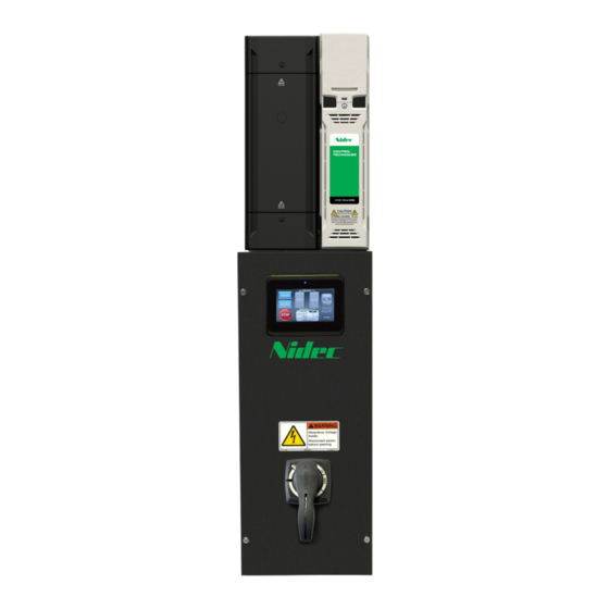
- Page 1 Installation and Commissioning Guide HMI Bypass Controller HVAC Drive H300 Part Number: PSD-H300HMIBP-ICG Issue: 2.0...
-
Page 2: Table Of Contents
Contents Section 1 - Introduction ..................5 Section 2 - Installation Instructions ..............6 2.1 Receiving ......................6 2.2 Nameplate Information ................6 2.2.1 Labels ....................6 2.2.1.1 HMI Bypass Package Label ............6 2.2.1.2 Typical Standard VFD Rating Label ..........7 2.3 Part Number Identification ................8 2.4 Mounting &... - Page 3 3.2.7 Auto-Reset Setup ................28 3.2.8 Remote Control ..................29 3.2.10 Modbus RTU Configuration ...............30 3.2.10.1 Serial Data Format ..............31 3.2.11 Alarm Response ................31 3.2.12 Alarm Response - Fireman’s Override ..........32 3.2.13 Advanced I/O Settings ..............32 3.2.14 PID Setup ..................33 3.2.14.1 PID Setup - Sleep/Wake Function ..........33 3.2.15 Miscellaneous ...................34 3.3 Touchscreen HMI Settings ................34 3.3.1 Setting the Date and Time ..............35...
- Page 4 The information contained within this document is proprietary to Nidec Control Techniques and may not be copied, reproduced or transmitted to other parties without the expressed written consent of Nidec Control Techniques. No patent liability is assumed with respect to the use of information contained herein.
-
Page 5: Section 1 - Introduction
Section 1 - Introduction Thank you for purchasing your Nidec Control Techniques HMI bypass package. This manual provides information concerning the installation, wiring and general startup procedures for the HVAC Drive H300 line of HMI bypass packages. The HMI bypass is a complete integrated HVAC control... -
Page 6: Section 2 - Installation Instructions
3 Check the unit for physical damage which may have occurred during shipping. If any part of the package is missing or damaged, notify the carrier and your Nidec Control Techniques representative immediately. 3 Verify that all internal hardware (i.e. components, screws, etc.) is properly seated and fastened securely. -
Page 7: Typical Standard Vfd Rating Label
2.2.1.2 Typical Standard VFD Rating Label * This label is only applicable to VFD size 7 and above. Refer to the following page Section 2.3 Part Number Identification for further information relating to the labels. HMI Bypass Controller Installation and Commissioning Guide... -
Page 8: Part Number Identification
3 = HVAC Drive H300 ambient temperatures. factory for a custom quote. X = HVAC Drive H300 AFE Order from Eden Prairie, MN: orders.cta@mail.nidec.com PLH 2018 v1.0 www.hvacr-drives.com Page 21 P: 952-995-8111, F: 952-995-8129 HMI Bypass Controller Installation and Commissioning Guide... -
Page 9: Mounting & Clearances
2.4 Mounting & Clearances Install the HMI bypass package on a vertical surface and allow the following minimum clearances for normal heat dissipation. 12 in 6 in 12 in 6 in WARNING WARNING WARNING WARNING Potentially hazardous voltage Potentially hazardous voltage can exist within this device. -
Page 10: Wiring And Precautions
2.5 Wiring and Precautions 2.5.1 General 1. DO NOT connect or disconnect wiring or perform signal checks while the power supply is turned ON. 2. Connect the power supply wiring to the HMI bypass input terminals L1, L2 and L3 on the main circuit disconnect device. 3. -
Page 11: Output Wiring
Connect the main power supply, motor and control wiring using the following recommended conduit locations. The input phase sequence does not affect the output phase sequence of the VFD. It will affect bypass sequence and motor rotation direction. Recommended conduit entrances control wiring WARNING WARNING... -
Page 12: Control Circuit Wiring
2.5.4 Control Circuit Wiring 2.5.4.1 Analog Input A 4 to 20 mA analog input signal is available by connecting to the customer terminals 5 (+) and 4 (-). Terminal No. Description 0V Common Analog Speed/Frequency Reference 2.5.4.2 Digital Inputs The HMI bypass combines digital inputs from the HVAC H300 VFD and SI-I/O option module. -
Page 13: Digital Output
There is one (1) form C relay output. Terminal No. Description 0V Damper Control Contact Common Damper Control Contact (NO) 2.5.4.4 Digital Output There is one (1) digital output. (24 Vdc). Terminal No. Description Auto Mode Selected 2.5.4.5 Additional HVAC H300 VFD Connections Additional analog inputs and outputs are available by making connections directly to the HVAC H300 VFD. -
Page 14: Grounding
2.5.5 Grounding Never ground the HMI bypass package in common with welding machines, motors or other high current electrical equipment. Run all ground wires in a separate conduit. When using several electronic bypass packages side by side, ground as shown below. -
Page 15: Customer Connection Diagram
2.5.7 Customer Connection Diagram NOTE: For Emergency Bypass Operation (i.e. drive removal or +24 Vdc supply failure) bypass contactor can be engaged to run the motor across the line by moving Jumper (41-100) to (44- EB). Note the thermal overload protection is protecting the motor. -
Page 16: Hvac Drive H300 Hmi Bypass Schematic
2.5.8 HVAC Drive H300 HMI Bypass Schematic HMI Bypass Controller Installation and Commissioning Guide... - Page 17 HMI Bypass Controller Installation and Commissioning Guide...
-
Page 18: Inspection
2.6 Inspection Once all wiring is complete, verify that: 1. All wiring is installed. 2. Excess screws, metal filings and wire clippings are removed from inside the unit(s). 3. Screws and fasteners are securely tightened. 4. Exposed wiring has no contact with other wiring or terminals. Section 3 –... -
Page 19: Main Control Screen
3.1.2 Main Control Screen From the main screen, users can control the state of the bypass system and navigate to system configuration (settings) and status menus. HAND: Pressing this icon will put the bypass system in Hand Mode. In VFD and Hand Mode, the system will run at a manually selected frequency and the bypass contactor will automatically close if BYP (Bypass Mode) is selected and the VFD output is off. -
Page 20: Drive Status And System Diagnostics
3.1.3 Drive Status and System Diagnostics 3.1.3.1 General Status The drive status screen displays basic VFD information. Motor RPM: Displays the estimated speed of the motor. Current Magnitude: The instantaneous drive output current scaled so that it represents the r.m.s. phase current in Amps under steady-state conditions. Output Power: Displays the current power output of the VFD. -
Page 21: Additional Drive Status
3.1.3.2 Additional Drive Status This screen displays the estimated total running cost of the HMI bypass system and filter change reminders. Power Consumption: Displays the current power consumption of the VFD. Power Cost per kWhr: Defines the cost of energy per kWh in cents. Total Power Consumption: Displays the accumulated VFD power consumption. -
Page 22: Graphical Trend Viewer
If all above checks are good, attempt to reset the overload relay using the overload reset button. • Fire Alarm: A 24V input signal on Fire Alarm input (24) is present. Recommended action: » If an external fire alarm is not present, verify customer terminal block wiring. -
Page 23: I/O Status
3.1.3.5 I/O Status Displays the status of inputs, outputs, and relays in the system, terminals 22 through 74. MORE: Navigates to the second I/O status page. The second I/O status page displays the SI-I/O expansion module I/O, terminals 202 through 223 and analog input terminals 5 and 6. -
Page 24: Motor Map
3.2.1 Motor Map The HMI Bypass motor data can be found or entered in the Motor Data screen. The Motor Data screen also allows access to the autotune feature and Advanced VFD settings. Motor data can usually be found on the nameplate of the motor. - Page 25 3.2.2 Autotune The VFD is able to perform either a stationary or a rotating autotune. The motor must be at a standstill before an autotune is enabled. A rotating autotune should be used whenever possible, so the measured value of power factor of the motor is used by the drive.
-
Page 26: Advanced Vfd Settings
3.2.3 Advanced VFD Settings The Advanced VFD Settings menu allows access to advanced settings of the VFD. Voltage Boost: Defines the level of voltage boost at 0Hz when using a fixed V to F relationship. Current Limit: Limits the current when the motor is being accelerated or decelerated. -
Page 27: Skip Frequencies
3.2.4 Skip Frequencies The skip reference functions are available to prevent continuous operation within a specified speed range (i.e., where mechanical resonance may occur). The HMI Bypass allows up to three (3) speed/frequencies to be skipped. Skip Reference: Sets the center point of the speed/frequency reference the VFD should skip. -
Page 28: I/O Settings
3.2.6 I/O Settings The I/O Setting screen allows the setup of the system I/O. Analog Speed Reference Mode: Defines the input mode for analog input speed/frequency reference (5). The following list provides a brief explanation of the available settings. For further information see HVAC H300 User Guide. •... -
Page 29: Remote Control
Auto-Reset Delay: The time interval between reset attempts. The HMI Bypass default is 5 seconds. Hold Drive Healthy: If set to “ON,” the fault alarm relay will not close until all reset attempts have been exhausted. Note: If Hold Drive Healthy is set to “ON” and if Number of Auto-Reset Attempts is set to “6”... -
Page 30: Modbus Rtu Configuration
3.2.9 Serial Communications This screen allows for the configuration of settings needed for serial communication. BAN (Building Automation Network) Protocol: Selects the network protocol. 0 = Modbus RTU 1 = BACnet 2 = Metasys N2 Open MS/TP Max Master Mac Address: (BACnet use only) this is the highest address that the bypass system will use when looking for the next master on the network with which token passing can be achieved. -
Page 31: Serial Data Format
3.2.10.1 Serial Data Format Defines how the serial data packets are formatted. Stop bits, parity, and standard/modified address schemes. 3.2.11 Alarm Response The Alarm Response screen allows for the configuration of the Automatic Bypass and Damper Fault Response features. Automatic Bypass: When enabled, the system will automatically go into Bypass Mode after a fault is detected and after “Auto-Bypass Time”... -
Page 32: Alarm Response - Fireman's Override
3.2.12 Alarm Response - Fireman’s Override This Alarm Response screen allows for the configuration of the Fireman’s Override feature. Fireman’s Override: When enabled, a fireman override command will ignore “Motor Overload” and “Damper Timeout” faults. The system will still wait for a damper feedback, but if no feedback is detected and a timeout is triggered, the system will bypass anyway. -
Page 33: Pid Setup
3.2.14 PID Setup The PID setup screen allows for the configuration of the onboard PID feature. Control Action: Direct control means that as the PID error increases, the speed reference also increases. A common application for direct control is a cooling/ heating fan. -
Page 34: Miscellaneous
Wake Delay: Defines the elapsed time before the system restarts the motor if the wake function is active. Sleep Delay: Defines the elapsed time before the system stops the motor if the sleep function is active. Max Sleep Offset time: Defines the maximum amount of time that the Sleep Offset function can be active. -
Page 35: Setting The Date And Time
Note: It is recommended that the HMI SETTINGS menu be accessed for Date/ Time setting and Backlight setting only. Changing any other HMI settings may prevent the HMI Bypass from operating satisfactorily. In order to navigate to the HMI Settings menu, click YES. 3.3.1 Setting the Date and Time LCD Touchscreen HMI XP-Runtime Menu Press the “Settings”... -
Page 36: Touchscreen Lcd Hmi Software Update Procedure
A window will appear with date and time. Set values to current date and time. Press “OK” when complete. To return to the HMI Bypass menus press the “Start” icon from the XP-Runtime menu. To navigate back to the HMI Bypass menus press the “Start” icon from the XP-Runtime menu 3.4 Touchscreen LCD HMI Software Update Procedure To update the LCD touchscreen HMI program from a portable USB drive:... -
Page 37: Section 4 - Startup
6. Choose the correct file name from the list and hit “OK” 7. Wait while the HMI extracts and installs the new project file. Section 4 – Startup This section provides guidance on how to setup an HVAC Drive H300 HMI Bypass. -
Page 38: Setup Wizard Process
4.1 Setup Wizard Process The Setup Wizard will step you through the Motor Data, Motor Ramps/Limits, I/O Settings, Auto-Reset Setup, Remote Control, Alarm Response – Automatic Bypass, and Alarm Response – Fireman’s Override setup screens. If the PID Controller is to be used, upon selection, it will step you through the Advanced I/O Settings, PID Setup, and PID Setup –... - Page 39 Step 2 – Motor Data: Enter motor nameplate information in the following settings. • Rated Frequency: Motor nameplate value • Current: Motor nameplate value • Speed: Motor nameplate value • Voltage: Motor nameplate value • Power Factor: Motor nameplate value Once complete press the “NEXT”...
- Page 40 Step 5 - Auto-Reset Setup: If Auto-Reset feature is desired, set the number auto-reset attempts and the delay between attempts when the VFD trips. Setting Hold Drive Healthy to “ON” will hold the VFD drive health status to “Healthy” until the Auto-Reset attempts are complete.
- Page 41 If the application requires the HMI Bypass to disable in the case of loss of Damper Feedback input (terminal 23) and enable the Damper Timeout trip, then the Damper Fault Response should be set to “ENABLED.” If enabled, set Damper Timeout for the time between loss of Damper Feedback input (terminal 23) and when the HMI Bypass initiates a Damper Timeout trip.
-
Page 42: Checking Motor Rotation
If “NO” then setup the HMI Bypass basic setup is complete and the Setup Wizard will return to the System Settings screen. If “YES” the Setup Wizard will continue to the optional PID setup screen. Optional Step - Onboard PID Controller: If the Onboard PID Controller will be used, the Setup Wizard will continue to the Advanced I/O Settings, PID Setup, and PID Setup –... -
Page 43: Normal Operation
Press the HAND icon on the HMI bypass touchscreen. The HAND icon will be highlighted indicating the HMI bypass is in local control. This will start the motor across the line. Check motor rotation. To stop the motor press STOP on the HMI touchscreen. Note the direction of rotation as the motor shaft begins to rotate as compared to the required rotation direction. -
Page 44: Starting Operation
4.4.2 Starting Operation There are two (2) basic steps required to begin operation. Step 1 – Select the operation mode by pressing the VFD or BYP (bypass) icon. You must select one of these modes. For VFD operation, press the VFD icon. For bypass operation press the BYP (bypass) icon. -
Page 45: Section 5 - Troubleshooting
Section 5 - Troubleshooting The HMI will annunciate VFD and system alarms and trips when supply and control power is applied. The chart below is intended to assist with troubleshooting a system when the HMI is not illuminated or no fault is indicated. Symptom Indications Corrective Actions... - Page 46 Symptom Indications Corrective Actions Motor does not - Check mechanical motor to load couplings rotate when Bypass are intact mode is selected and - Ensure that motor connections are made HAND is pressed or and no bypass to motor disconnects are open AUTO is pressed and - Check that the mechanical load is not the Auto-Run input...
-
Page 47: Section 6 - Additional Information
Section 6 - Additional Information 6.1 Specifications - HVAC Drive H300 HMI Bypass The HMI bypass package features a user-friendly application-specific full-color live-graphics LCD touch screen HMI (Human Machine Interface) to simplify operation and provide status indication. 6.1.1 Approvals • VFD Section – UL508C »... -
Page 48: Options
• Ambient operating temp: +32 to +104 °F (0 to +40 ˚C) • Storage temp: -40 to +140 ˚F (-40 to +60 ˚C) • 95% relative humidity, non-condensing • Input voltage: +10%, -10%; 208, 230, 460 and 575 Vac • Protected from exposure to direct sunlight 6.1.4 Options •... -
Page 49: Vfd Parameter Access
6.3 VFD Parameter Access The HVAC Drive H300 VFD parameters settings required for operation in a bypass system are set at the factory. Adjustments can be made to VFD parameters via the HMI for all standard applications. If there is a need to access advanced parameters not accessible via the HMI there are 2 methods available: 1. -
Page 50: Hvac Drive H300 Hmi Bypass Parameter Defaults
To configure a drive to HVAC Drive H300 HMI Bypass factory defaults (examples: replacement VFD or existing VFD that is reset to HVAC Drive H300 defaults), from the System Settings screen select the Default Settings icon. Select “YES” to restore the HVAC Drive H300 HMI Bypass to system defaults. Select “NO”... - Page 51 Parameter HVAC Drive Paremeter Description Bypass Value H300 Default 05.009 Rated Voltage Drive rating Drive rating 05.018 Maximum Switching Frequency 3 kHz 3 kHz 05.027 Enable Slip Compensation 06.015 Drive Enable 06.019 Date/Time Selector Acc Powered Local Keypad 06.043 Control Word Enable 06.048 Supply Loss Detection Level Drive rating...
- Page 52 Parameter HVAC Drive Paremeter Description Bypass Value H300 Default 10.034 Number Of Auto-reset Attempts None 10.035 Auto-reset Delay 10.0 s 5.0 s 00.00 Ω 75.00 Ω 10.061 Braking Resistor Resistance 11.024 Serial Mode 7 1 NP 8 2 NP 11.044 User Security Status All Menus 12.010...
- Page 53 Notes: HMI Bypass Controller Installation and Commissioning Guide...
- Page 54 Notes: HMI Bypass Controller Installation and Commissioning Guide...
- Page 55 Notes: HMI Bypass Controller Installation and Commissioning Guide...
- Page 56 ©2019 Control Techniques a division of Nidec Motor Corporation. The information contained in this manual is for guidance only and does not form part of any contract. The accuracy cannot be guaranteed as Nidec Control Techniques have an ongoing process of development and reserve the right to change the specification of their products without notice.
Need help?
Do you have a question about the Control Techniques HVAC Drive H300 HMI Bypass and is the answer not in the manual?
Questions and answers