Advertisement
Quick Links
Advertisement

Subscribe to Our Youtube Channel
Related Manuals for Walker Edison HANB5B


Summary of Contents for Walker Edison HANB5B
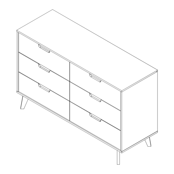
- Page 1 Item: HANB5B Assembly Instructions Please visit our website for the most current instructions, assembly tips, to report damage or request parts. www.walkeredison.com Revised 07/2022 - V1 Copyright © 2018, by Walker Edison Furniture Co., LLC. All rights reserved.
-
Page 2: General Assembly Guidelines
V. A Phillips head screwdriver and a hammer are required for the assembly of this product (not included) VI. Power tools should not be used to assemble this product. Copyright © 2018, by Walker Edison Furniture Co., LLC. All rights reserved. -
Page 3: Parts List
Top Panel Right Side Panel Left Side Panel Bottom Panel Drawer Front Right Drawer Side Left Drawer Side Drawer Back Drawer Bottom Division Back Panel Bottom Back Panel Spacer Copyright © 2018, by Walker Edison Furniture Co., LLC. All rights reserved. -
Page 4: Hardware List
Ø 10x13mm Plastic Bushing 6 pcs 330mm Slide 330mm Slide 6 pcs The hardware quantities listed above are required for proper assembly. Some extra hardware may also have been included. Copyright © 2018, by Walker Edison Furniture Co., LLC. All rights reserved. - Page 5 (B) into parts (1,2,3) with philips head screwdriver. Step 2 Ø 22x17mm 139mm Insert plastic bush (P) into central foot (K2). Insert Ø 10x13mm adjustable foot (E) into bush (P). Copyright © 2018, by Walker Edison Furniture Co., LLC. All rights reserved.
- Page 6 Step 4 Step 2 Step 1 2º Hole 330mm Ø3,5x14mm Attach slide (R1) and part 13) into part (2) with screw (D,N) and philips head screwdriver. Ø 6x20mm Copyright © 2018, by Walker Edison Furniture Co., LLC. All rights reserved.
- Page 7 Attach slides (L1) and part 13) into part (3) with screw (D,N) and philips head screwdriver. Ø 6x20mm Step 6 Insert cam bolt (B) into part (1) with philips head screwdriver. Ø6x31mm Copyright © 2018, by Walker Edison Furniture Co., LLC. All rights reserved.
- Page 8 Painted part Step 2 Step 1 2º Hole 300mm 300mm Ø3,5x14mm Attach slides (L1,R1) into part (10) with screw (D,M) and philips head screwdriver. Ø 6x20mm Copyright © 2018, by Walker Edison Furniture Co., LLC. All rights reserved.
- Page 9 Secure part (12) into part (3) using cam lock (C) with philips head screwdriver . Ø15x10mm Step 9 Secure part (12) into part (2) using cam lock (C) with philips head screwdriver. Ø15x10mm Copyright © 2018, by Walker Edison Furniture Co., LLC. All rights reserved.
- Page 10 Secure part (4) into parts (2,3) using screw (F) and philips head screwdriver. Ø4x40mm Step 11 Secure part (10) into part (4) using screw (F) and philips head screwdriver. Ø4x40mm Copyright © 2018, by Walker Edison Furniture Co., LLC. All rights reserved. P.10...
- Page 11 Slide back panel (11) into side panel (2,3,12) with the painted outside. Step 13 Secure part (1) into parts (2,3,10) using cam lock Ø15x10mm (C) and philips head screwdriver . Copyright © 2018, by Walker Edison Furniture Co., LLC. All rights reserved. P.11...
- Page 12 (B) into parts (5) with philips head screwdriver. Ø6x31mm Step 15 Secure parts (6,7) into part (8) using screw (F) and philips head screwdriver. Slide part (9) into grooves according diagram. Ø4x40mm Copyright © 2018, by Walker Edison Furniture Co., LLC. All rights reserved. P.12...
- Page 13 Secure part (05) into parts (6,7) using cam lock (C) with philips head screwdriver. Ø15x10mm Step 17 Ø3,5x14mm 330mm Attach slides (L2,R2) into parts (6,7) with screw (D) and philips head screwdriver. 330mm Copyright © 2018, by Walker Edison Furniture Co., LLC. All rights reserved. P.13...
- Page 14 Attach support (H) to parts (5,8) with screw (D) and philips head screwdriver. 14x14mm Step 19 Ø 3,5x14 Attach support (H) to parts (1,2,3,11,12) with screw (D) and philips head screwdriver. 14x14mm Copyright © 2018, by Walker Edison Furniture Co., LLC. All rights reserved. P.14...
- Page 15 Place sticker (I) over holes according diagram. Ø 19mm Step 21 Adjust the foot (K2) level with the floor according diagram. Copyright © 2018, by Walker Edison Furniture Co., LLC. All rights reserved. P.15...
- Page 16 Name and address information for the manufacturer responsible for the anti-tip hardware and date of production can be found on the label on the back of the furniture. Copyright © 2018, by Walker Edison Furniture Co., LLC. All rights reserved. P.16...
Need help?
Do you have a question about the HANB5B and is the answer not in the manual?
Questions and answers