
Related Manuals for Endress+Hauser OUSTF10


Summary of Contents for Endress+Hauser OUSTF10
- Page 1 Products Solutions Services BA00500C/07/EN/03.24-00 71643600 2024-01-31 Operating Instructions OUSTF10 Optical sensor with the OUA260 flow assembly for the measurement of undissolved solids...
-
Page 2: Table Of Contents
Table of contents OUSTF10 Table of contents About this document ... 3 Repair ......26 Warnings . -
Page 3: About This Document
OUSTF10 About this document About this document Warnings Structure of information Meaning This symbol alerts you to a dangerous situation. DANGER Failure to avoid the dangerous situation will result in a fatal or serious injury. Causes (/consequences) If necessary, Consequences of non- compliance (if applicable) ‣... -
Page 4: Basic Safety Instructions
Basic safety instructions OUSTF10 Basic safety instructions Requirements of the personnel • Installation, commissioning, operation and maintenance of the measuring system may be carried out only by specially trained technical personnel. • The technical personnel must be authorized by the plant operator to carry out the specified activities. -
Page 5: Operational Safety
OUSTF10 Basic safety instructions Operational safety Before commissioning the entire measuring point: Verify that all connections are correct. Ensure that electrical cables and hose connections are undamaged. Do not operate damaged products, and protect them against unintentional operation. Label damaged products as defective. -
Page 6: Product Description
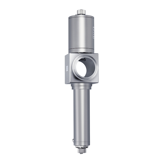
Product description OUSTF10 Product description Sensor design A0054700 1 Sensor with flow assembly OUA260 Cable connection Lamp module Flow assembly OUA260 (depending on version) Detector module Connection for air purge function (optional) The detector and lamp can vary on account of the individual options ordered. -
Page 7: Incoming Acceptance And Product Identification
OUSTF10 Incoming acceptance and product identification A0029413 2 Scattered light measurement Light source (lamp) Orifice plates and lenses Scattered light Scattered light detector Transmitted light detector Neutral broadband density filter with anti-reflex coating Medium Broadband NIR filter (780 nm +) -
Page 8: Product Identification
Click the product overview. A new window opens. Here you fill information pertaining to your device, including the product documentation. Manufacturer address Endress+Hauser Conducta Inc. 4123 East La Palma Avenue, Suite 200 Anaheim, CA 92807 USA Scope of delivery The scope of delivery comprises the following, : •... -
Page 9: Mounting Procedure
Mounting procedure Mounting requirements 5.1.1 Measuring system An optical measuring system comprises: • Sensor (photometer) OUSTF10 • Transmitter, e. g. Liquiline CM44P • Cable set, e. g. CUK80 • Assembly OUA260 3 Example of a measuring system with a photometer sensor... - Page 10 Mounting procedure OUSTF10 5.1.2 Dimensions A0031511 4 Sensor module Dimension of lamp → Table Dimension of detector → Table Assembly; see Technical Information for assembly Lamp type Dimension A in mm (inch) Collimated incandescent lamp 151.3 (5.96) Detector type...
- Page 11 OUSTF10 Mounting procedure 5.1.3 Mounting bracket A0028250 5 Mounting angles. The arrows indicate the direction of medium flow in the pipe. Suitable mounting angle, better than C Optimum mounting angle, best installation position Acceptable mounting angle Mounting angle to be avoided...
-
Page 12: Mounting The Sensor
Purge gas supply via connections to the detector and lamp of the process photometer Compressed air or nitrogen supply Air drier (not required for nitrogen) Pressure regulator Flow controller Process photometer OUSTF10 The purge gas must be clean and dry (ultra zero air). Maximum gauge pressure: 0.07 bar (1 psi) Flow rate:... -
Page 13: Post-Mounting Checks
OUSTF10 Electrical connection NOTICE Mounting errors Possibility of sensor damage, twisted cables or similar ‣ Make sure that the sensor bodies are protected against damage from external forces - such as trolleys on adjacent paths. ‣ Remove the cable before you screw the lamp or detector onto the flow assembly. -
Page 14: Lamp Voltage
Electrical connection OUSTF10 A0028384 7 Connecting cable OUSTF10 Light source (lamp) power supply Signals of scattered light and transmitted light detector CM44P terminal Cable color Assignment YE (thick) Lamp voltage + YE (thin) Detection of lamp voltage + BK (thin) - Page 15 OUSTF10 Electrical connection The safe area is separated from the hazardous area by two safety barriers MTL7760AC. 105 (4.13) 8 Safety barrier, dimensions in mm (inch) The safety barrier may only have a very low leak current since the optical signals from the sensor can be in the nanoampere range.
- Page 16 Electrical connection OUSTF10 Connect the other end of the cable to the transmitter. Photometer 2x MTL7760ac Transmitter (Det.) C (1) A (1) SH (1) C (2) A (2) SH (1) 6.3.2 Connecting the hazardous area lamp using a junction box The hazardous area lamp (EXP-1) must be connected to the transmitter using a certified junction box.
-
Page 17: Ensuring The Degree Of Protection
OUSTF10 Electrical connection EXP-1 Transmitter ATEX II 2G Ex db IIC T5 Gb FM Cl.1, Div. 1, Groups B, C, D A0029440 9 Connecting the hazardous area lamp to CM44P via a junction box Ensuring the degree of protection... -
Page 18: Post-Connection Check
Electrical connection OUSTF10 Post-connection check Device condition and specifications Notes Are the sensor, assembly and cable free from damage on the outside? Visual inspection Electrical connection Notes Does the supply voltage of the connected transmitter match the data on the... -
Page 19: Commissioning
OUSTF10 Commissioning Commissioning Function check Prior to initial commissioning, ensure that: • The sensor is correctly installed • The electrical connection is correct Calibrating/adjusting the sensor Measuring points consisting of a photometer sensor, flow assembly (if provided) and a transmitter are adjusted at the factory. Normally adjustment is not required when commissioning for the first time. - Page 20 Commissioning OUSTF10 You can dilute the suspension to produce a series of optical standard solutions. You can check the calibration of the measuring system with the standard solutions. Stock suspension [ml] Ultrapure water [ml] 97.5 It is not recommended to dilute the stock suspension below 4 FTU.
-
Page 21: Maintenance
OUSTF10 Maintenance There are two ways to calibrate/adjust with CM44P: • Calibration Zero point calibration or two-point calibration • Application adjustment You create a maximum of five calibration datasets which are each adapted to your particular application. Calibrating the measuring system ‣... -
Page 22: Replacing The Hazardous Area Lamp
Maintenance OUSTF10 Replacing the hazardous area lamp The disassembly and assembly process for the hazardous area lamp is the same as for the non-hazardous area version. Make sure you use the right spare parts kit. Replacing the collimated incandescent lamp Preparation Switch off the lamp using the software function on the transmitter. - Page 23 OUSTF10 Maintenance Loosen the two securing screws on the optical project unit (a) and then carefully unscrew the optical projection unit (b). Dispose of the lamp unit, along with the cable connector, in accordance with local regulations. Insert the new lamp unit into the optical projection unit and retighten the securing screws.
-
Page 24: Replacing The Sensor Window And Seal
Maintenance OUSTF10 Screw the lamp module clockwise onto the flow assembly. A zero point adjustment is required after replacing the lamp. Replacing the sensor window and seal Operating Instructions for Flowcell OUA260, BA01600C Operating Instructions for CUA261, BA01652C If you have mounted the sensor in a VARIVENT flow assembly using the CUA261 adapter, refer to the Operating Instructions of the adapter for information on removal and on replacing the optical windows. - Page 25 OUSTF10 Maintenance Remove the window ring along with the O-ring on the inside towards the assembly. Gently push the optical window out of the assembly. If the window jams, apply some acetone around the window seal (O-ring) and wait a few minutes for it to take effect.
-
Page 26: Repair
The product must be returned if repairs or a factory calibration are required, or if the wrong product was ordered or delivered. As an ISO-certified company and also due to legal regulations, Endress+Hauser is obliged to follow certain procedures when handling any returned products that have been in contact with medium. -
Page 27: Accessories
• Pre-terminated and labeled cables for connecting analog photometer sensors • Product Configurator on the product page: www.endress.com/cuk80 OUK20 cable set • Pre-terminated and labeled cables for connecting OUSTF10- and OUSAF2x-type sensors to Memograph CVM40 • Order as per product structure Endress+Hauser... -
Page 28: Technical Data
Technical data OUSTF10 Technical data 11.1 Input 11.1.1 Measured variable Process-absorption 11.1.2 Measuring range 11.1.3 Wavelength Broadband (VIS and NIR) Broadband filter (780 nm and above) 11.2 Environment 11.2.1 Ambient temperature Non-hazardous area versions 0 to 55 °C (32 to 131 °F) Hazardous area versions 2 to 40 °C (36 to 104 °F) -
Page 29: Mechanical Construction
OUSTF10 Technical data 11.4 Mechanical construction 11.4.1 Dimensions → 10 11.4.2 Weight 1.225 kg (2.7 lbs.), without flow assembly 11.4.3 Materials Sensor housing Stainless steel 316L Assembly OUA260 Technical Information OUA260, TI00418C Assembly CUA261 Operating Instructions CUA261, BA01652C Cable connector ends Nickel-plated brass 11.4.4... -
Page 30: Index
Index OUSTF10 Index Mounting requirements ....9 Mounting the sensor ....12 Accessories . - Page 32 *71643600* 71643600 www.addresses.endress.com...
Need help?
Do you have a question about the OUSTF10 and is the answer not in the manual?
Questions and answers