
Subscribe to Our Youtube Channel
Related Manuals for Christopeit Sport CL 3


Summary of Contents for Christopeit Sport CL 3
- Page 1 Heimsport-Trainingsgera t CL 3 Art.-Nr. 1305/1306 Montage- und Bedienungsanleitung Assembly and exercise instructions...
-
Page 2: Table Of Contents
Inhaltsu bersicht Contents Page 1. Wichtige Empehlungen und Sicherheitshinweise Seite 2 2. Einzelteileu bersicht Seite 3 - 4 3. Stu ckliste Seite 5 - 6 4. Montageanleitung mit Explosionsdarstellungen Seite 7 - 10 5. Benutzung des Gera tes Seite 10 6. Computeranleitung Seite 11 7. Trainingsanleitung Seite 12 Sehr geehrte Kundin, sehr geehrter Kunde... -
Page 5: Stu Ckliste
Stu ckliste - Ersatzteilliste Wenn ein Bauteil nicht in Ordnung ist oder ehlt, oder wenn Sie in Zukunt ein Ersatzteil beno tigen, wenden Sie sich bitte an uns. CL 3 Art.-Nr. 1305/1306 Adresse: Top-Sports Gilles GmbH Technische Daten: Stand: 01. 10. 2013 Friedrichstr. - Page 6 Abbildungs- Bezeichnung Abmessung Menge Montiert an ET-Nummer Stück Abbildungs Nr. Unterlegscheibe 8//16 31+33 36-9962-CR Selbstsichernde Mutter 39-9918-CR Kugellager 30/45 36-9713-02-BT Lageraunahme 36-9713-01-BT Mutter 36-9713-05-BT Schraube 3x10 39-10127-SW Lagerabdeckung 1 36-9713-06-BT Unterlegscheibe 23//38 36-9713-07-BT Flachriemen 48+56 36-1305-06-BT Tretkurbelscheibe 36-1305-07-BT Achsmutter M10x1 39-9820-SW Schraube M6x50...
-
Page 7: Montageanleitung Mit Explosionsdarstellungen
Montageanleitung Entnehmen Sie alle Einzelteile der Verpackung, legen diese au den Boden und kontrollieren die Vollza hligkeit grob anhand der Montageschritte. Zu beachten ist dabei, dass einige Teile direkt mit dem Grund- gestell verbunden sind und vormontiert wurden. Des Weiteren sind auch einige andere Einzelteile schon zu Einheiten zusam- mengeu ... - Page 8 Schritt 3: Montage des Sattels (33) und des Sattelstu tzrohres (16). 1. Den Sattel (33) mit der Sitzfa che nach unten hinlegen. 2. Die Aunahmeplatte des Sattelschlittens (34) au die oben lie- gende Ru ckseite des Sattels (33) aufegen. Die Gewindestu cke au...
- Page 9 Schritt 5: Montage des Lenkers (27) am Lenkerstu tzrohr (17). 1. Den Lenker (27) zum Lenkerstu tzrohr (17) u hren, und so aus- richten, dass das Lochbild des Lenkers und des Lenkerstu tzrohr u bereinstimmen. Au...
-
Page 10: Benutzung Des Gera Tes
Schritt 7: Kontrolle 1. Alle Verschraubungen und Steckverbindungen au ordnungs- gema ße Montage und Funktion pru en. Die Montage ist hiermit beendet. 2. Wenn alles in Ordnung ist, mit leichten Widerstandseinstellungen mit dem Gera t vertraut machen und die individuellen Einstellun- gen vornehmen. -
Page 11: Computeranleitung
Computeranleitung Achtung: Der mitgelieerte Computer bietet den gro ßten Trainingskomort. Jeder Zur Pulsmessung mu ssen die beiden Kontaktfa chen der Pulsmessgri- trainingsrelevante Wert wird in einem entsprechenden Sichtenster Einheit mit beiden Ha nden gleichzeitig gegrien werden. Dabei sollten sich angezeigt. -
Page 12: Trainingsanleitung
Trainingsanleitung Um spu rbare ko rperliche und gesundheitliche Verbesserungen zu erreichen, 4. Motivation mu ssen u r die Bestimmung des erorderlichen Trainingsauwandes die Der Schlu ssel u r ein erolgreiches Programm ist ein regelma ßiges Training. olgenden Faktoren beachtet werden: Sie sollten sich einen esten Zeitpunkt und Platz pro Trainingstag einrichten und sich auch geistig au das Training vorbereiten. Trainieren Sie nur gut 1. Intensita t: gelaunt und halten Sie sich stets Ihr Ziel vor Augen. Bei kontinuierlichem Die Stue der ko rperlichen Belastung beim Training muß den Punkt der Training werden Sie Tag u ... -
Page 13: Important Recommendations And SaEty InOrmation
Contents 1. Summary o Parts Page 3 - 4 2. Important Recommendations and Saety Inormation Page 13 3. Parts List Page 14 - 15 4. Assembly Instructions With Exploded Diagrams Page 16 - 19 5. Mount, Use & Dismount Page 19 6. Computer instructions Page 20 7. Training Instructions Page 21 Dear customer, We congratulate you on your purchase o this home training sports unit and hope that we will have a great deal o pleasure with it. Please take heed o the enclosed notes and instructions and ollow them closely concerning assembly and use. Please do not hesitate to contact us at any time i you should have any questions. Top-Sports Gilles GmbH Important Recommendations and Safety Instructions 12. -
Page 14: Parts List
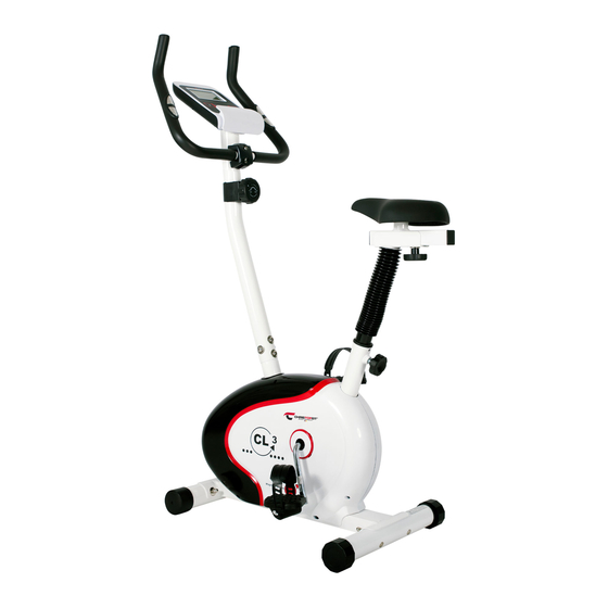
Parts List – Spare Parts List Please contact us i any components are deective or missing, or i you need any spare parts or replacements in uture. CL 3 Art.-Nr. 1305/1306 Technical data: Issue: 01. 10. 2013 Top-Sports Gilles GmbH Friedrichstr. 55 • Magnetic brake system 42551 Velbert • approx. 7 KG fywheel Teleon: +49 (0) 20 51 - 6 06 70 • 8-manually adjustable load steps Teleax: +49 (0) 20 51 - 6 06 74 4 •... - Page 15 Illustration imensions Quantity Attached to ET number signation illustration No. Washer 8//16 31+33 36-9962-CR Nylon nut 39-9918-CR Ball bearing 30/45 36-9713-02-BT Bearing holder 36-9713-01-BT 36-9713-05-BT Screw 3x10 39-10127-SW Bearing cover 1 36-9713-06-BT Big washer 23//38 36-9713-07-BT Belt 48+56 36-1305-06-BT Belt wheel 36-1305-07-BT Axle nut M10x1...
-
Page 16: Assembly Instructions With Exploded Diagrams
Assembly Instructions Remove all the separate parts rom the packaging, lay them on the foor and check roughly that all are there on the base o the assembly steps. Please note that a number o parts have been connected directly to the main rame and preassembled. In addition, there are several other individual parts that have been attached to separate units. - Page 17 Step 3: Installation o saddle (33) and saddle support (16). 1. Place the saddle (33) with the seat surace downwards. 2. Place the retaining plate o the saddle slide (34) on the upwards pointing bottom o the saddle (33). The threaded pieces on the bottom o...
- Page 18 Step 5: Installation o handlebar (27) at handlebar support (17). 1. Place the handlebar (27) against the handlebar support (17) and adjust so that the hole patterns in the handlebar and the handlebar support are aligned. Put one spring washer (30) and washer (39) on each screw (31).
-
Page 19: Mount, Use & Dismount
Step 7: Checks 1. Check the correct installation and unction o all screwed and plug connections. Installation is thereby complete. 2. When everything is in order, amiliarise yoursel with the machine at a low resistance setting and make your individual adjustments. Note: Please keep the tool set and the instructions in a sae place as these may be required or repairs or spare parts orders becoming... -
Page 20: Computer Instructions
Computer instructions Keys: 1. „F“ key: Pressing this key once briefy makes it possible to change rom one unction The supplied computer allows the most convenient training. Every value to another, i.e. the respective unctions can be selected or which entries relevant to training is displayed in a corresponding window. -
Page 21: Training Instructions
Training instructions You must consider the ollowing actors in determining the amount o training eort required in order to attain tangible physical and health benefts: 1. Intensity: The level o physical exertion in training must exceed the level o normal exertion without reaching the point o breathlessness and / or exhaustion. A suitable guideline or eective training can be taken rom the pulse rate. During training this should rise to the region o between 70% to 85% o the maximum pulse rate (see the table and ormular or determination and calculation o this). During the frst weeks, the pulse rate should remain at the lower end o this region, at around 70% o the maximum pulse rate. In the course o the ollo- wing weeks and months, the pulse rate should be slowly raised to the upper limit o 85% o the maximum pulse rate. The better the physical condition o the person doing the exercise, the more the level o training should be encreased to remain in the region o between 70% to 85% o the maximum pulse rate. This should be done by lengthening the time or the training and / or encreasing the level o difculty. I the pulse rate is not shown on the computer display or i or saety reasons you wish to check your pulse rate, which could have been displayed wrongly due to error in use, etc., you can do the ollowing: a. Pulse rate measurement in the conventional way (eeling the pulse at the wrist, or example, and counting the number o beats in one minute). b. Pulse rate measurement with a suitable specialised device (available rom dealers specialising in health-related equipment). 2.Frequency Most experts recommend a combination o health-conscious nutrition, which must be determined on the basis o your training goal, and physical training three times a week. A normal adult must train twice a week to maintain his... - Page 24 Service Bei Reklamationen, notwendigen Ersatzteilbestellungen oder © by Top-Sports Gilles GmbH Reparaturen wenden Sie sich bitte an unsere Service Abteilung. D-42551 Velbert (Germany) Service: Top-Sports Gilles GmbH Tel.: +49 (0)2051/6067-0 Friedrichstrasse 55 info@christopeit-sport.com Fax: +49 (0)2051/6067-44 D - 42551 Velbert http://www.christopeit-sport.com...
Need help?
Do you have a question about the CL 3 and is the answer not in the manual?
Questions and answers