Advertisement
Quick Links
www.ti.com
EVM User's Guide: TPS1213Q1EVM TPS1213-Q1
TPS1213-Q1 Evaluation Module for Smart High-Side
Driver
Description
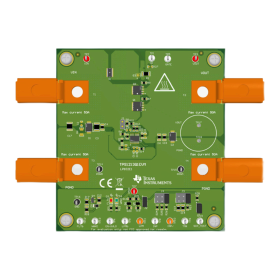
The TPS1213Q1EVM allows reference circuit
evaluation of TI's TPS1213-Q1 smart high-side driver.
The TPS1213-Q1 device has operating range of
3.5V-40V and has main path gate drive with 1.69-A
strength to enable switching parallel MOSFETs in high
current designs. The TPS12130-Q1 has low-power
mode to support always ON loads while consuming
28 µA (typ). In low power mode, only the low power
path FET is kept ON and the main FETs are turned
OFF to save IQ. The device provides adjustable
short circuit protection with configurable auto-retry
and latch-off fault behavior.
SLUUCV7 – DECEMBER 2023
Submit Document Feedback
Features
•
3.5-V to 40-V operating voltage range
•
15-A to 50-A adjustable short circuit protection
using onboard jumpers
•
Programmable short-circuit protection delay
•
Programmable load wakeup threshold
•
Programmable auto-retry and latch options
•
LED status indication for fault and Active mode
Applications
•
Automotive 12 V BMS
•
Power distribution box
Copyright © 2023 Texas Instruments Incorporated
TPS1213-Q1 Evaluation Module for Smart High-Side Driver
Description
1
Advertisement

Related Manuals for Texas Instruments TPS1213Q1EVM


Summary of Contents for Texas Instruments TPS1213Q1EVM
- Page 1 Description EVM User's Guide: TPS1213Q1EVM TPS1213-Q1 TPS1213-Q1 Evaluation Module for Smart High-Side Driver Description Features The TPS1213Q1EVM allows reference circuit • 3.5-V to 40-V operating voltage range evaluation of TI's TPS1213-Q1 smart high-side driver. • 15-A to 50-A adjustable short circuit protection...
-
Page 2: Kit Contents
EVM schematics, bill of materials, assembly drawings, and top and bottom board layouts. CAUTION Hot surface. Contact can cause burns. Do not touch. 1.2 Kit Contents Table 1-1. TPS1213Q1EVM Kit Contents Item Description Quantity TPS1213Q1EVM 1.3 Specification... - Page 3 Hardware 2 Hardware The TPS1213Q1EVM evaluation board enables evaluation of TPS12130-Q1 driver. The input power is applied between connectors T1 and T3 while T2 and T4 provide an output connection to the load, Refer to the schematic Figure 4-1...
- Page 4 Hardware www.ti.com 2.1 General Configurations 2.1.1 Physical Access Table 2-2 lists the TPS1213Q1EVM Evaluation Board input and output connector functionality. Table 2-3 Table 2-4 describe the test point availability and the jumper functionality. Table 2-2. Input and Output Connector Functionality...
- Page 5 One resistive load or equivalent that can tolerate up to 50-A DC load at 40 V and capable of the output short. SLUUCV7 – DECEMBER 2023 TPS1213-Q1 Evaluation Module for Smart High-Side Driver Submit Document Feedback Copyright © 2023 Texas Instruments Incorporated...
- Page 6 Implementation Results www.ti.com 3 Implementation Results 3.1 Test Setup and Procedures Make sure the evaluation board has default jumper settings as shown in Table 3-1. Table 3-1. Default Jumper Setting for TPS1213Q1EVM Evaluation Board Install Install OPEN Oscilloscope Voltmeter Positive...
- Page 7 2. Now, enable the EN/UVLO to HIGH to verify the startup profile of BST, G2 and SRC. Figure 3-2. Start-Up Profile of Low Power Path (LPMb = Low, VIN= 12 V, No-load, CBST = 470 nF) SLUUCV7 – DECEMBER 2023 TPS1213-Q1 Evaluation Module for Smart High-Side Driver Submit Document Feedback Copyright © 2023 Texas Instruments Incorporated...
- Page 8 Figure 3-4. Zoom-in View of State Transition from LPM to Active Mode (LPMb = Low, VIN= 12 V, EN/UVLO = High) TPS1213-Q1 Evaluation Module for Smart High-Side Driver SLUUCV7 – DECEMBER 2023 Submit Document Feedback Copyright © 2023 Texas Instruments Incorporated...
- Page 9 Implementation Results Figure 3-5. As LPMb = Low, INP Has No Control on G1 Even After WAKEUP SLUUCV7 – DECEMBER 2023 TPS1213-Q1 Evaluation Module for Smart High-Side Driver Submit Document Feedback Copyright © 2023 Texas Instruments Incorporated...
- Page 10 Figure 3-6. State Transition from LPM to Active Mode (LPMb = Low to High, VIN= 12 V, No-load) Figure 3-7. With LPMb = Low to High, INP Gained Control on G1 (VIN= 12 V, No-load) TPS1213-Q1 Evaluation Module for Smart High-Side Driver SLUUCV7 – DECEMBER 2023 Submit Document Feedback Copyright © 2023 Texas Instruments Incorporated...
- Page 11 Figure 3-8. Inrush Current Profile with 220 µF at the Output (LPMb = Low) Figure 3-9. Inrush Current Profile with 220 µF at the Output and 0.5A Load (LPMb = Low) SLUUCV7 – DECEMBER 2023 TPS1213-Q1 Evaluation Module for Smart High-Side Driver Submit Document Feedback Copyright © 2023 Texas Instruments Incorporated...
- Page 12 3.1.5 Overload and Short Circuit Protection Test Use the following instructions to perform over current test on the TPS1213Q1EVM 1. Turn ON the power supply and set the power supply output VIN=12 V, current limit = 50 A. 2. Set the Short Circuit Protection (SCP) threshold at 50 A by installing jumper J4 in 5-6 position and install jumper J3 in 1-2 position to set 1-ms delay.
- Page 13 Implementation Results Figure 3-12. Latch-off Response of TPS12130-Q1 for an Overcurrent Fault Figure 3-13. Output Short-Circuit Response of TPS12130-Q1 SLUUCV7 – DECEMBER 2023 TPS1213-Q1 Evaluation Module for Smart High-Side Driver Submit Document Feedback Copyright © 2023 Texas Instruments Incorporated...
- Page 14 68nF 680nF 100k 3.74k 12.4k TP12 TP13 5.6V FLTb WAKE FLTb WAKE 10ms PGND Figure 4-1. TPS1213Q1EVM: Evaluation Module Schematic TPS1213-Q1 Evaluation Module for Smart High-Side Driver SLUUCV7 – DECEMBER 2023 Submit Document Feedback Copyright © 2023 Texas Instruments Incorporated...
- Page 15 EVAL Board, and Figure 4-4 through Figure 4-7 show PCB layout images. Figure 4-2. TPS1213Q1EVM Board Top Overlay Figure 4-3. TPS1213Q1EVM Board Bottom Overlay Figure 4-4. TPS1213Q1EVM Board Top Layer Figure 4-5. TPS1213Q1EVM Board Bottom Layer SLUUCV7 – DECEMBER 2023...
- Page 16 Hardware Design Files www.ti.com Figure 4-7. TPS1213Q1EVM Board Inner Routing Figure 4-6. TPS1213Q1EVM Board Inner Signal Layer Layer TPS1213-Q1 Evaluation Module for Smart High-Side Driver SLUUCV7 – DECEMBER 2023 Submit Document Feedback Copyright © 2023 Texas Instruments Incorporated...
- Page 17 Hardware Design Files 4.3 Bill Of Materials (BoM) Table 4-1 lists the EVM bill of materials. Table 4-1. TPS1213Q1EVM Bill Of Materials Designator Quantity Description Part Number Manufacturer !PCB1 Printed Circuit Board LP102 C3, C17 CAP, CERM, 10 uF, 50 V, +/- 20%, X7R, 1210...
- Page 18 Hardware Design Files www.ti.com Table 4-1. TPS1213Q1EVM Bill Of Materials (continued) Designator Quantity Description Part Number Manufacturer RES, 0, 0.75 W, AEC-Q200 Grade 0, 1206 CRCW12060000Z0EAHP Vishay-Dale RES, 100, 1%, 0.1 W, AEC-Q200 Grade 0, 0603 ERJ-3EKF1000V Panasonic RES, 470 k, 1%, 0.1 W, 0603...
- Page 19 Hardware Design Files Table 4-1. TPS1213Q1EVM Bill Of Materials (continued) Designator Quantity Description Part Number Manufacturer CAP, CERM, 0.47 uF, 25 V, +/- 10%, X7R, AEC- CGA3E3X7R1E474K080AB Q200 Grade 1, 0603 FID1, FID2, FID3, FID4, Fiducial mark. FID5, FID6 N-Channel 40 V 2.9A (Ta), 5.7A (Tc) 2W (Ta), 7.5W...
- Page 20 Additional Information www.ti.com 5 Additional Information Trademarks All trademarks are the property of their respective owners. TPS1213-Q1 Evaluation Module for Smart High-Side Driver SLUUCV7 – DECEMBER 2023 Submit Document Feedback Copyright © 2023 Texas Instruments Incorporated...
- Page 21 STANDARD TERMS FOR EVALUATION MODULES Delivery: TI delivers TI evaluation boards, kits, or modules, including any accompanying demonstration software, components, and/or documentation which may be provided together or separately (collectively, an “EVM” or “EVMs”) to the User (“User”) in accordance with the terms set forth herein.
- Page 22 www.ti.com Regulatory Notices: 3.1 United States 3.1.1 Notice applicable to EVMs not FCC-Approved: FCC NOTICE: This kit is designed to allow product developers to evaluate electronic components, circuitry, or software associated with the kit to determine whether to incorporate such items in a finished product and software developers to write software applications for use with the end product.
- Page 23 www.ti.com Concernant les EVMs avec antennes détachables Conformément à la réglementation d'Industrie Canada, le présent émetteur radio peut fonctionner avec une antenne d'un type et d'un gain maximal (ou inférieur) approuvé pour l'émetteur par Industrie Canada. Dans le but de réduire les risques de brouillage radioélectrique à...
- Page 24 www.ti.com EVM Use Restrictions and Warnings: 4.1 EVMS ARE NOT FOR USE IN FUNCTIONAL SAFETY AND/OR SAFETY CRITICAL EVALUATIONS, INCLUDING BUT NOT LIMITED TO EVALUATIONS OF LIFE SUPPORT APPLICATIONS. 4.2 User must read and apply the user guide and other available documentation provided by TI regarding the EVM prior to handling or using the EVM, including without limitation any warning or restriction notices.
- Page 25 Notwithstanding the foregoing, any judgment may be enforced in any United States or foreign court, and TI may seek injunctive relief in any United States or foreign court. Mailing Address: Texas Instruments, Post Office Box 655303, Dallas, Texas 75265 Copyright © 2023, Texas Instruments Incorporated...
-
Page 26: Important Notice
TI products. TI’s provision of these resources does not expand or otherwise alter TI’s applicable warranties or warranty disclaimers for TI products. TI objects to and rejects any additional or different terms you may have proposed. IMPORTANT NOTICE Mailing Address: Texas Instruments, Post Office Box 655303, Dallas, Texas 75265 Copyright © 2023, Texas Instruments Incorporated...
Need help?
Do you have a question about the TPS1213Q1EVM and is the answer not in the manual?
Questions and answers