Page 1
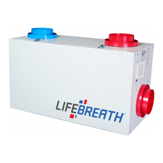
Operation and Installation Manual RNC Series 2 Speed Electronics RNC155 RNC200* RNC95* RNC5-TPD* RNC120D RNC10 RNC20 Residential New Construction Series (RNC) Heat Recovery Ventilators This product earned the E ERGY STAR by meeting strict energy efficiency guidelines set by atural Resources Canada and the US EPA. It meets E ERGY STAR requirements only when used in Canada.
Introduction Warranty..................2 Before installation, careful consideration must be Getting to Know your RNC Series HRV given to how this system will operate if connected Selecting the Ventilation Rate that is right for You to any other piece of mechanical equipment, i.e. a...
Getting to Know your RNC Series Heat Recovery Ventilator (HRV) Thank you for purchasing a LIFEBREATH® Heat Recovery Ventilator • exhausts the stale, contaminated air, found in today’s tight buildings. (HRV). The HRV provides fresh air to your home while recovering •...
The Lifestyle RNC Digital Control Part #99-DX-01 Part # 99-DX-01 The Lifestyle RNC Digital Control offers advanced features to Instruction card control your home's ventilation. Key Features Fan Speed • 2 Speed Fan setting (Low-1/High-2) Indicator Humidity • Standby setting (Fan speed 0) 20/40/60 Minute Indicator High Speed...
The Lifestyle RNC Ventilation Control Part #99-BC-01 The Lifestyle RNC Ventilation Control offers ON/OFF, High Speed/Low speed plus an electronic dehumidistat. Instruction card Key Features • 2 Speed Fan setting (Low/High) • Electronic Dehumidistat Dehumidistat Indicator LEDs • Instruction Card is inserted in the control indicator •...
Optional Timers The timer will override the Operational Mode (regardless of the setting) and initiate high speed ventilation. Upon completion of the If the system does not have a main control installed, the HRV timer cycle, the HRV will return to your selected Operational Terminal Block must have a jumper installed between 2 (ON) Mode and speed setting.
Maintenance Routine for HRV 1. Inspect Exterior Hoods at least once a month. 6. Clean Duct Work if Required Make sure exhaust and fresh air supply hoods are not blocked or The duct work running to and from the HRV may accumulate dirt. restricted by leaves, grass, or snow.
WEIGHT 52 lbs. (23.6 kg) SHIPPING WEIGHT 56 lbs (25.4 kg) *Sensible Efficiency @ 60 cfm (28 L/s) 32°F (0°C) RNC SERIES ELECTRONICS • Built-in Relay for Interfacing to furnace *Sensible Efficiency • A standard ON/OFF switch can be added to provide Low/High Ventilation or ON/OFF @ 61 cfm (29 L/s) -13°F (-25°C)
Page 9
Port Configuration and Airflow Model RNC95 In order to make the RNC95 as space efficient as possible, the RNC95 Port Specifications INDOOR supply and return ports are converted from round to oval The RNC95 Heat Recovery Ventilator (HRV) has been designed shape.
WEIGHT 71 lbs. (32.5 kg) SHIPPING WEIGHT 73 lbs. (33.5 kg) *Sensible Efficiency @ 65 cfm (31 L/s) 32°F (0°C) RNC SERIES ELECTRONICS • Built-in Relay for Interfacing to furnace *Sensible Efficiency • A standard ON/OFF switch can be added to provide Low/High Ventilation or ON/OFF @ 68 cfm (32 L/s) -13°F (-25°C)
WEIGHT 71 lbs. (32.5 kg) SHIPPING WEIGHT 73 lbs (33.5 kg) *Sensible Efficiency @ 66 cfm (31 L/s) 32°F (0°C) RNC SERIES ELECTRONICS • Built-in Relay for Interfacing to furnace *Sensible Efficiency • A standard ON/OFF switch can be added to provide Low/High Ventilation or ON/OFF @ 109 cfm (51 L/s) -13°F (-25°C)
*Sensible Efficiency @ 67 cfm (32 L/s) 32°F (0°C) RNC SERIES ELECTRONICS • Built-in Relay for Interfacing to furnace • A standard ON/OFF switch can be added to *Sensible Efficiency provide Low/High Ventilation or ON/OFF functionality in order to meet building standards.•...
*Sensible Efficiency @ 119 cfm (56 L/s) 32°F (0°C) RNC SERIES ELECTRONICS • Built-in Relay for Interfacing to furnace • A standard ON/OFF switch can be added to provide *Sensible Efficiency Low/High Ventilation or ON/OFF functionality in order to meet building standards.• Optional @ 117 cfm (55 L/s) -13°F (-25°C)
WEIGHT 61 lbs. (28 kg) SHIPPING WEIGHT 64 lbs. (29 kg) @ 66 cfm (31 L/s) 32°F (0°C) *Sensible Efficiency RNC SERIES ELECTRONICS • Built-in Relay for Interfacing to furnace @ 66 cfm (31 L/s) 32°F (0°C) • A standard ON/OFF switch can be added to provide Low/High Ventilation or ON/OFF *Sensible Efficiency functionality in order to meet building standards.
WEIGHT 42 lbs. (19 kg.) SHIPPING WEIGHT 45 lbs. (20.5 kg.) @ 70 cfm (33 L/s) 32°F (0°C) *Sensible Efficiency RNC SERIES ELECTRONICS • Built-in Relay for Interfacing to furnace @ 70 cfm (33 L/s) 32°F (0°C) • A standard ON/OFF switch can be added to provide Low/High Ventilation or ON/OFF *Sensible Efficiency functionality in order to meet building standards.
Engineering Data - HRV Model RNC120D Option 1 - Horizontal Duct Configuration Dimensions inches FRESH AIR STALE AIR TO FROM OUTSIDE OUTSIDE HANGING STRAPS STALE AIR FROM BUILDING FRESH AIR TO BUILDING 25 1/8” (637 mm) BOTTOM VIEW FOR HORIZONTAL MOUNT SERVICE CLEARANCE FROM BOTTOM STALE AIR OF UNIT IS MINIMUM 3’0”...
Installation Methods The Three Methods of Installation Installing the Ducting Between the HRV & Living The three methods of installation for the HRV system are: Areas in the House • The Simplified installation. A well designed and installed ducting system will allow the HRV to operate at its maximum efficiency.
Page 18
Simplified Installation Diagrams Simplified Installation (Return/Return Method) Key Points • The HRV must be balanced. • It is mandatory that the furnace blower run continuously or HRV operation be interlocked with the furnace blower. (Refer to “Interlocking the HRV to an Air Handler/Furnace Blower.”) •...
Page 19
Partially Dedicated Installation Diagrams Partially Dedicated System This installation enables stale air to be drawn from the poorest air quality areas of the home (bathrooms, kitchen). Key Points • The HRV must be balanced. • It is recommended that the furnace blower run continuously or HRV operation be interlocked with the furnace blower to evenly distribute the fresh air throughout the house.(Refer to “Interlocking the HRV...
Page 20
Fully Dedicated Installation Diagrams Fully Dedicated System This is a stand alone HRV system which is not connected to a force air system. Stale air is drawn from key areas of the home (bathroom, kitchen) while fresh air is supplied to main living areas.
Installation Location Install the unit in a heated space that provides convenient space for WARNING service access. A typical location is in either a mechanical room or an area close to the outside wall within close proximity to where Improper installation, adjustment, alteration, the weatherhoods are mounted.
Suspending the RNC120D ATTENTION Horizontal Installation The unit must be mounted level for proper drainage of the condensate pans. JOIST FASTENERS (not supplied) STRAPS SCREWS (supplied) DETAIL Using full length hanger straps is recommended for vibration control, but can be shorter if required. Vertical Installation “L”...
Grilles Adjustable grilles should be used to balance the flow rates into and The Lifebreath Kitchen Grille out of various rooms. The grilles should not be adjusted after balancing the unit. Grilles or diffusers should be positioned high on the wall or in the Removable filter ceiling.
Grille Fittings Rough-in Metal Fitting Stack Head Elbow (Part # 99-RIMF 4/5/6/8/) (Part # 99-WF4/ 99-WF6) Use this rough-in fitting before the drywall is installed. Use this rough-in fitting before the drywall is installed. • Nail or screw the fitting onto the floor joist. This fitting is ideal for running ducting through 2”...
Weatherhood Installation Installing the Ducting from the Lifebreath Weatherhoods Fixed covered weatherhoods have a built-in bird screen with a 1/4" Weatherhoods to the HRV (6mm) mesh to prevent foreign objects from entering the The inner and outer liners of the flexible insulated duct must be ductwork.
Installation of the Main Control Standard Series Controls may be installed onto a flush mounted 2" x 4" electrical switch box or it may be surface mounted onto a wall. Pay special attention not to damage the Contact Only 1 master control should be installed to a ventilation system (the Face Plate on this illustration may not be exactly the same as Pins when attaching and detaching the Face Plate.
Installation and Operation of 20 Minute and 20/40/60 Minute Timers Operating your Lifestyle 20 Minute or 20/40/60 Minute Timers Press and release the Select Button to activate high speed override. The High Speed Status Light will illuminate and the unit will run on high speed ventilation for 20 minutes. High Speed The Lifestyle 20/40/60 Minute timers provide an extended Status Lights...
Interlocking the HRV to an Air handler/Furnace Blower Connecting the HRV as illustrated will ensure the Air CAUTION Handler/Furnace Blower Motor is operating whenever the HRV is ventilating. The HRV must be interlocked to the Furnace/Air Handler Consideration should be given to competing with a Simplified Installation (Return/Return Installation) airflows when connecting the HRV in and should be interlocked with a Partially Dedicated...
When sampling an air flow, various attachments are available for use on a magnehelic gauge or digital manometer. Consult with your Lifebreath Distributor for available options such as a pitot tube, flow measuring station, and an air flow measuring probe.
Balancing the Air Flows with a Pitot Tube STEP 1. STEP 2. Drill a 3/16” hole in the duct (ideally 3 feet downstream of Insert the Pitot tube with the tip facing towards the air any elbows or bends and 1 foot upstream of any elbows stream in the Stale Air From Building air stream.
Air Flow Balancing using the Door Ports Available on Selected Models Step 4 Door balancing ports (not on all models) are designed to be used in conjunction with a Magnehelic Gauge or Digital Manometer to Close the HRV Door. Initiate power and operate the HRV on high speed.
Page 32
Airflow Reference Charts RNC5-TPD Models have 3 airflow charts, since they have an installer-adjustable high speed. Refer to your model’s Technical Data Sheet for instructions on how to adjust the high speed and balance according to the following charts. Hi 2 Hi 1 Hi 3 RNC5-TPD...
Balancing Dampers The RNC155 and RNC200 models have factory installed Balancing Dampers located in the “Fresh Air to Building” and “Stale Air from Building” collars. Installations where the HRV is ducted directly to the return of the furnace/air handler may require The RNC5-TPD model has factory installed Balancing Dampers additional dampening on the fresh air to building located in the “Fresh Air to Building”...
Troubleshooting your HRV System SYMPTOM CAUSE SOLUTION Poor Air Flows • 1/4” (6 mm) mesh on the outside hoods is plugged • clean exterior hoods or vents • filters plugged • remove and clean filter • core obstructed • remove and clean core •...
Residential Wiring Diagram Model RNC120D LEGEND HIGH VOLTAGE Thermistor 12V LOW VOLTAGE (Not on all units) BLUE BLACK GREEN WHITE AUTO- DEFROST TRANSFORMER DETAIL BLACK WHITE Note: If any of the original AUTO-TRANSFORMER DETAIL PINS 1, 2 AND 3 ARE OPTIONAL wire supplied with the unit Motors PLUG IN CONNECTOR...
Page 36
Residential Wiring Diagram Models RNC95/RNC10/RNC20/RNC155 LEGEND HIGH VOLTAGE Thermistor 12V LOW VOLTAGE (Not on all units) BLUE BLACK GREEN WHITE AUTO- TRANSFORMER DEFROST DETAIL GREEN Note: If any of the original wire supplied with the unit must be replaced, use only TEW certified wire.
Page 37
Residential Wiring Diagram Model RNC200 LEGEND HIGH VOLTAGE Thermistor 12V LOW VOLTAGE (Not on all units) BLUE BLACK GREEN WHITE AUTO- TRANSFORMER GREEN WHITE DEFROST YELLOW DETAIL BROWN BLACK BLUE Speed Controller AUTO-TRANSFORMER DETAIL PINS 1, 2 AND 3 ARE OPTIONAL PLUG IN CONNECTOR Note: If any of the original wire supplied with the unit...
Page 38
PIN 3 - BROWN PIN 6 - BLACK DEFROST DETAILS PCB PLUG - IN PLUG IN CONNECTOR BLACK BLACK ORANGE ORANGE PIN 1 - RED PIN 2 - ORANGE BI-DIRECTIONAL PIN 3 - BLACK DAMPER MOTOR PIN 4 - SPARE 59-TPD-3SP info@lifebreath.com...
Page 40
LEAVE FOR HOMEOWNER TO BE COMPLETED BY CONTRACTOR AFTER INSTALLATION Installing Contractor _________________________________________Telephone / Contact _____________________ Serial Number______________________________________________Installation Date ________________________ Model _________________________________________________________________________________________ Register for your warranty at www.lifebreath.com Airia will require the Model and Serial Number to register the unit. info@lifebreath.com...
Need help?
Do you have a question about the RNC Series and is the answer not in the manual?
Questions and answers