GIGAIPC SDM Series Quick Start Manual
Smart display module
Hide thumbs
Also See for SDM Series:
- Quick start manual (145 pages) ,
- User manual (26 pages) ,
- Quick start manual (25 pages)

Related Manuals for GIGAIPC SDM Series


Summary of Contents for GIGAIPC SDM Series
-
Page 1: Smart Display Module Series
SDM-1335AL (MRLU5AL-SI) Smart Display Module Series Quick Start Guide www.gigaipc.com... -
Page 2: Copyright Notice
While reasonable efforts have been made in the preparation of this document to assure its accuracy, GIGAIPC assumes no liabilities resulting from errors or omissions in this document, or from the use of the information contained herein. -
Page 3: Acknowledgement
Core, Atom are trademarks of Intel Corporation ITE is a trademark of Integrated Technology Express, Inc. • • IBM, PC/AT, PS/2, and VGA are trademarks of International Business Machines Corporation. All other product names or trademarks are properties of their respective owners. www.gigaipc.com... -
Page 4: Packing List
Quantity Internal Wi-Fi Cable (P/N: 25CA0-090004-A5S (90mm) + 25CA0-280003-A5S (280mm)) External Wi-Fi 5 Antenna (P/N: 25CA0-112001-A5S) External Wi-Fi 6/6E Antenna (P/N: 25CA0-163002-A5S) If any of these items are missing or damaged, please contact your distributor or sales representative immediately. www.gigaipc.com... -
Page 5: About This Document
(if any), its specifications, dimensions, jumper/ connector settings/definitions, and driver installation instructions (if any), to facilitate users in setting up their product. Users may refer to the GIGAIPC.com for the latest version of this document. www.gigaipc.com... -
Page 6: Safety Precautions
Make sure the device is installed near a power outlet and is easily accessible. 10. Keep this device away from humidity. 11. Place the device on a solid surface during installation to prevent falls 12. Do not cover the openings on the device to ensure optimal heat dissipation. www.gigaipc.com... - Page 7 18. D O N O T L E AV E T H I S D E V I C E I N A N U N C O N T R O L L E D ENVIRONMENT WITH TEMPERATURES BEYOND THE DEVICE’S PERMITTED STORAGE TEMPERATURES (SEE CHAPTER 1) TO PREVENT DAMAGE. www.gigaipc.com...
-
Page 8: Fcc Statement
Il y a un risque d’explosion si la batterie est remplacée de façon incorrecte. Ne la remplacer qu’avec le même modèle ou équivalent recommandé par le constructeur. Recycler les batteries usées en accord avec les instructions du fabricant et les directives gouvernementales de recyclage. www.gigaipc.com... -
Page 9: Table Of Contents
SODIMMA, SODIMMB (DDR5 SO-DIMM sockets) ..23 2.2.7 M2M (1 x M.2 slot, 2280 M-key) ........24 2.2.8 M2E (1 x M.2 slot, 2230 E-key) ........25 2.2.9 CPU_FAN (CPU Fan connector) ........26 2.2.10 BATTERY (1 x Battery cable connector) ......27 www.gigaipc.com... - Page 10 4.3.12 I n t e l ( R ) E t h e r n e t C o n t r o l l e r ( 3 ) I 2 2 5 - L M - 74:56:3C:BB:18:98 ............53 Chipset ................54 Security ................. 55 Boot ................58 Save & Exit ..............59 www.gigaipc.com...
-
Page 11: Chapter 1 - Product Specifications
Chapter 1 Chapter 1 - Product Specifications www.gigaipc.com... - Page 12 104.3 114.2 www.gigaipc.com...
-
Page 13: Specifications
3 x USB 3.2 type A Gen 2x1 1 x USB 3.2 type C Gen 2x1 Rear I/O 1 x PWR LED 1 x HDD LED 2 x External Antenna Holes (Optional) 1 x Reset button 1 x Power button www.gigaipc.com... - Page 14 SDM-1335AL Motherboard (MRLU5AL-SI) Onboard TPM 2.0 security chip INFINEON SLB9670VQ2.0 Windows® 10/11 (x64) Compatibility Operating temperature: 0°C to 55°C Operating Operating humidity: 0%-90% (non-condensing) Properties Non-operating temperature: -40°C to 85°C Non-operating humidity: 0%-95% (non-condensing) www.gigaipc.com...
-
Page 15: Chapter 2 - Hardware Information
Chapter 2 Chapter 2 – Hardware Information www.gigaipc.com... -
Page 16: Jumpers And Connectors
Jumpers and Connectors www.gigaipc.com... - Page 17 1 x Reset button (Top) PSW_RST 1 x Power button (Bottom) SODIMMA 2 x DDR5 SO-DIMM sockets SODIMMB 1 x M.2 slot, 2280 M-key 1 x M.2 slot, 2230 M-key CPU_FAN 1 x CPU Fan connector BATTERY 1 x Battery cable connector www.gigaipc.com...
-
Page 18: Hdmi_20, Hdmi_21 (Hdmi Connector)
2.2.1 HDMI_20, HDMI_21 (HDMI Connector) HDMI 2 HDMI 1 HDMI 1 HDMI 2 HDMI Connector Connector PN Vendor D13-0715-19681 WALTA Pin No. Definition Pin No. Definition TX2p CLKn TX2n TX1p TX1n TX0p Hot Plug TX0n Detect CLKp www.gigaipc.com... -
Page 19: Usb32_2 (Usb 3.2 Type A Gen 2X1 Connector)
2.2.2 USB32_2 (USB 3.2 type A Gen 2x1 connector) USB 3.2 Gen 2x1 Connector Connector PN Vendor AUSB0174-K005C LOTES Definition Definition USB3_RX1n USB3_RX2n USB3_RX1p USB3_RX2p USB3_TX1n USB3_TX2n USB3_TX1p USB3_TX2p www.gigaipc.com... -
Page 20: Usbtc (Usb 3.2 Type C Gen 2X2 Connector)
2.2.3 USBTC (USB 3.2 type C Gen 2x2 connector) USB Type C Connector Connector PN Vendor DX07S024JJ2 Pin No. Definition Pin No. Definition TX1p TX2p TX1n TX2n VBUS VBUS VBUS VBUS RX2n RX1n RX2p RX1p www.gigaipc.com... -
Page 21: Usb32_1 (Usb 3.2 Type A Gen 2X1 Connector)
2.2.4 USB32_1 (USB 3.2 type A Gen 2x1 connector) USB 3.2 Gen 2x1 Connector Connector PN Vendor 18-A9830-6A33-A TCONN Definition Definition USB3_RX1n USB3_RX2n USB3_RX1p USB3_RX2p USB3_TX1n USB3_TX2n USB3_TX1p USB3_TX2p www.gigaipc.com... -
Page 22: Lan (Lan Connector)
2.2.5 LAN (LAN connector) LAN Connector State Description Orange On 2.5Gbps data rate Green On 1Gbps data rate 100M&10Mbps data rate Connector PN Vendor RB1-GB-0010 Pin No. Definition Pin No. Definition TX1+ TX3+ TX1- TX3- TX2+ TX4+ TX2- TX4- www.gigaipc.com... -
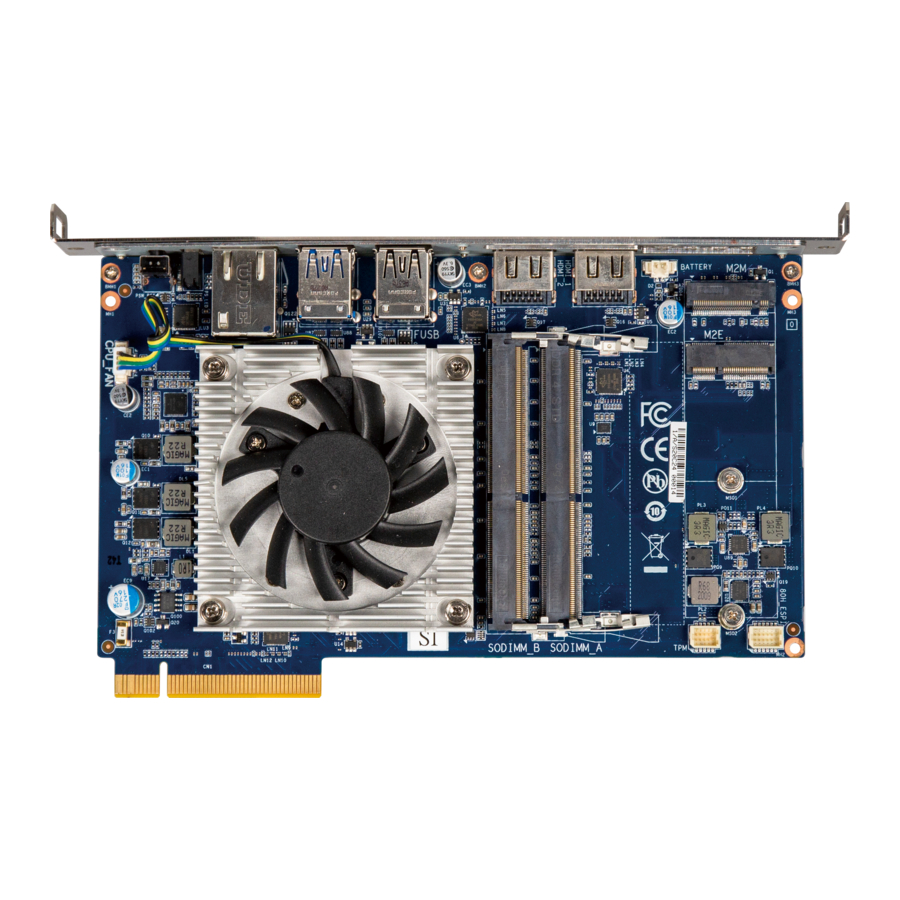
Page 23: Sodimma, Sodimmb (Ddr5 So-Dimm Sockets)
2.2.6 SODIMMA, SODIMMB (DDR5 SO-DIMM sockets) www.gigaipc.com... -
Page 24: M2M (1 X M.2 Slot, 2280 M-Key)
Wakeup PCIE Clockp PCIE3 TXn 3.3V PCIE3 TXp 3.3V 3.3V Pin No. Definition Pin No. Definition PCIE2 RXn 3.3V SUSCLK PCIE2 RXp Detect 3.3V 3.3V PCIE2 TXn 3.3V PCIE2 TXp PCIE1 RXn Connector PN Vendor PCIE1 RXp 80159-8523 BELLWETHER www.gigaipc.com... -
Page 25: M2E (1 X M.2 Slot, 2230 E-Key)
PCIE_RXn CL_Clock PCIE CLOCKp PCIE CLOCKn SUSCLK Pin No. Definition Pin No. Definition PCIE Clock PCIRST 3.3V Request 3.3V PCIE wake up BT_Disable WLAN_DISABLE 3.3V 3.3V Pin No. Definition Pin No. Definition Connector PN Vendor APCI0076-P002A LOTES PCIE_TXp PCIE_TXn www.gigaipc.com... -
Page 26: Cpu_Fan (Cpu Fan Connector)
2.2.9 CPU_FAN (CPU Fan connector) Pin 1 CPU FAN Connector Connector PN Vendor 85205-0470N ACES A1250WV-S-04PC JOINT-TECH Connector type Pin No. Definition 1x4pin header, pitch 1.25mm Detect Speed control www.gigaipc.com... -
Page 27: Battery (1 X Battery Cable Connector)
2.2.10 BATTERY (1 x Battery cable connector) Pin 1 Battery Connector Pin No. Definition 3.3V RTC Connector type 1x2pin connector, pitch 1.25mm www.gigaipc.com... -
Page 28: Chapter 3 - Sdm-L Installation
Chapter 3 Chapter 3 – SDM-L Installation www.gigaipc.com... -
Page 29: Dimension
Dimension 104.3 114.2 www.gigaipc.com... -
Page 30: Installation
Installation [SDM Install] * The image is for reference only. The actual product could be slightly different. www.gigaipc.com... - Page 31 Step 3. Step 4. Tighten up the screw which was Tighten up the screw which was previously removed. provided in the accessory kits on the bracket. * The image is for reference only. The actual product could be slightly different. www.gigaipc.com...
- Page 32 [Internal WiFi cable Install & Routing] Using 280mm Using 90mm Internal WiFi cable Internal WiFi cable * The image is for reference only. The actual product could be slightly different. www.gigaipc.com...
-
Page 33: Chapter 4 - Bios
Chapter 4 Chapter 4 – BIOS www.gigaipc.com... -
Page 34: Introduction
Execute command or enter the submenu Increase the numeric value or make + changes Decrease the numeric value or make – changes General Help Previous Values Load Optimized Defaults Settings Save changes & Exit the BIOS Setup program Exit the BIOS Setup program www.gigaipc.com... -
Page 35: The Main Menu
ME FW version Shows ME firmware version Set the Date for the system System Date (Format : Weekday - Month - Day - Year) Set the time for the system System Time (Format : Hour - Minute - Second) www.gigaipc.com... -
Page 36: Advanced
Advanced The Advanced menu is to configure the functions of hardware settings through submenu. Use arrow keys to move among the items, and press <Enter> to access into the related submenu. www.gigaipc.com... -
Page 37: Amt Configuration
Discrete LAN. Trigger CIRA boot Activate Remote Disabled : Disables TPM feature (Default setting) Assistance Process Enabled : Enables TPM feature To Un-configure ME without password. Unconfigure ME Disabled : Disables Unconfigure ME (Default settings) Enabled : Enables Unconfigure ME www.gigaipc.com... - Page 38 Disabled : Disables watchdog Timer (Default setting) Enabled : Enables watchdog Timer OS Timer Sets OS Watchdog Timer. BIOS Timer Sets BIOS Timer. Disabled : Disables ASF Sensors Table (Default setting) ASF Sensors Table Enabled : Enables ASF Sensors Table www.gigaipc.com...
- Page 39 Secure Erase Simulated : Performs SE flow without erasing SSD (Default setting) mode Real : Erase SSD Force Secure Erase on next boot. Force Secure Disabled : Disables Force Secure Erase (Default setting) Erase Enabled : Enables Force Secure Erase www.gigaipc.com...
- Page 40 Disabled : Disables One Click Recovery Windows recovery boot. Allows CSME to request Secureboot to be disabled for One Click Recovery. OCR Disable Secure Enabled : Enables One Click Recovery disable Secure Boot function. Boot (Default setting) Disabled : Disables One Click Recovery disable Secure Boot function. www.gigaipc.com...
- Page 41 Disabled : Disables remote platform erase feature. Platform Erase Enabled : Enables remote platform erase feature. (Default setting) Feature Change RPE SSD Erase Action behavior Simulated : performs RPE SSD Erase flow without erasing SSD. SSD Erase Mode (Default setting) Real : Erase SSD. www.gigaipc.com...
-
Page 42: Tpm Configuration
4.3.2 TPM Configuration Use TPM Configuration submenu to choose TPM interface. Item Description PTT : Internal TPM TPM Device dTPM : External TPM (When using External TPM module or having Selection TPM chip on MB)(Default setting) www.gigaipc.com... - Page 43 Disabled : Disables TPM feature None : No execution will be conducted (Default setting) Pending operation TPM clear : Set to clear data on TPM Enabled : Enables Platform Hiearchy (PH) Randomization. PH Randomization (Default setting) Disabled : Disables Platform Hiearchy (PH) Randomization. www.gigaipc.com...
-
Page 44: Cpu Configuration
Enabled : Enables Turbo Mode (Default setting) Turbo Mode Disabled : Disables Turbo Mode Command CPU to enter into low power consumption mode when CPU is under idle mode. C states Enabled : Enables C states (Default setting) Disabled : Disables C states www.gigaipc.com... -
Page 45: It8613 Super Io Configuration
Serial Port 1 Enabled : Enables allows you to configure the serial port settings Configuration Disabled : if Disabled, displays no configuration for the serial port Device settings : Display the specified Serial Port base I/O address and IRQ www.gigaipc.com... -
Page 46: Hardware Monitor
Normal : Fan speed set by BIOS default (Default setting) Control Full Speed : Set Fan operates at full speed CPU temperature Shows current CPU temperature System Shows current system temperature temperature CPU Fan Speed Shows current CPU fan Speed www.gigaipc.com... -
Page 47: S5 Rtc Wake Settings
Enable or Disable System to wake on a specific time. Disabled : Disables system to wake on a specific time (Default Wake system setting) from S5 Fixed Time : Enables system to wake on a specific time (Format : hr : min : sec) www.gigaipc.com... -
Page 48: Intel Txt Information
4.3.7 Intel TXT Information This submenu shows detailed Intel TXT informations. www.gigaipc.com... -
Page 49: Network Stack Configuration
Disabled : Disables IPv6 HTTP Support Enabled : Enables IPv6 HTTP Support PXE boot wait time Wait time in seconds, or use ESC key to abort the PXE boot. Media detect count Number of times the presence of media will be checked. www.gigaipc.com... -
Page 50: Nvme Configuration
4.3.9 NVMe Configuration NVMe Configuration shows information when your M.2 NVMe PCIe SSD is installed. www.gigaipc.com... -
Page 51: Offboard Sata Controller Configuration
4.3.10 Offboard SATA Controller Configuration www.gigaipc.com... -
Page 52: Tls Auth Configuration
Press [Enter] to configure advanced items : Server CA Configuration : Enroll Cert : 1. Enroll Cert Using File Enroll Cert 2. Cert GUID : Input digit character in 11111111-2222-3333-4444-1234567 890ab format. 3. Commit Changes and Exit 4. Discard Changes and Exit www.gigaipc.com... -
Page 53: 74:56:3C:bb:18:98
4.3.12 Intel(R) Ethernet Controller (3) I225-LM - 74:56:3C:BB:18:98 Shows Intel Ethernet controller information www.gigaipc.com... -
Page 54: Chipset
Enable/Disable I2C1 controller function I2C1 Controller Enabled : Enables I2C1 controller function Disabled : Disables I2C1 controller function (Default setting) Enable/Disable BIOS Lock function BIOS Lock Enabled : Enables BIOS Lock function (Default setting) Disabled : Disabled BIOS Lock funtion www.gigaipc.com... -
Page 55: Security
To set up Administrator's password Administrator Minimum length : 3 Password Maximum length : 20 To set up User's password User Password Minimum length : 3 Maximum length : 20 Secure Boot Press <Enter> to configure the advanced items www.gigaipc.com... - Page 56 No : Cancel to restore factory settings Reset To Setup Yes : Agree to setup mode Mode No : Cancel to setup mode Enables expert users to modify Secure boot policy variables without Key Management full authentication Press <Enter> to configure the advanced items www.gigaipc.com...
- Page 57 Device Guard ready system variables file system device must not list ’Microsof t MS UEFI CA Key UEFI CA’ Certificate in A u t h o r i z e d S i g n a t u r e database(db) www.gigaipc.com...
-
Page 58: Boot
Disabled : Disables Full screen LOGO Show on POST screen (Default setting) Enable/Disable Built-in EFI Shell Built-in EFI Shell Enabled : Enables Built-in EFI Shell Disabled : Disables Built-in EFI Shell (Default setting) Boot Option Choose/set the boot priority Priorities www.gigaipc.com... -
Page 59: Save & Exit
Yes : Agree to load optimized defaults No : Cancel to load optimized defaults Enable/Disable Me FW image re-flash function Me FW Image Enabled : Enables Me FW image re-flash function Re-Flash Disabled : Disables Me FW image re-flash function (Default setting) www.gigaipc.com...
Need help?
Do you have a question about the SDM Series and is the answer not in the manual?
Questions and answers