Table of Contents
Advertisement
MIDDLE MARKET
CUTTING WIDTH
ENGINE HP
WM - Middle Market
25 - 25" Cutting Deck
28 - 28" Cutting Deck
30 - 30" Cutting Deck
Thank you for buying a SNAPPER Product! Before operating your machine, read this manual carefully and pay
particular attention to the "IMPORTANT SAFETY INSTRUCTIONS" on Pages 2 & 3. Remember that all power
equipment can be dangerous if used improperly. Also keep in mind that SAFETY requires careful use in
accordance with the operating instructions and common sense!
COPYRIGHT © 2000
SNAPPER INC.
ALL RIGHTS RESERVED
Safety Instructions & Operator's Manual for
REAR ENGINE RIDING MOWER
MODEL NUMBER EXPLANATION
WM
28
08 - 8.0 HP Engine
09 - 9.0 HP Engine
10 - 10.0 HP Engine
10
21
B
21 - Series
Designation
SERIES 21
MODEL
M250821BE
M280921B
M281021BE
M300921B
M301021BE
WM280921B
WM301021BE
E
ENGINE OPTIONS
SERIES DESIGNATION
B - Briggs Engine
MANUAL No. 7-4023 (I.R. 9/19/00)
ENGINE TYPE
E - Electric Start
Advertisement
Table of Contents

Related Manuals for Snapper 21 Series


Summary of Contents for Snapper 21 Series
- Page 1 30 - 30” Cutting Deck 10 - 10.0 HP Engine Thank you for buying a SNAPPER Product! Before operating your machine, read this manual carefully and pay particular attention to the “IMPORTANT SAFETY INSTRUCTIONS” on Pages 2 & 3. Remember that all power equipment can be dangerous if used improperly.
-
Page 2: Important Safety Instructions
If you have any questions pertaining to your machine which your dealer cannot answer to your satisfaction, call or write the Customer Service Department at SNAPPER, McDonough, Georgia 30253. Phone: (1-800-935-2967). - Page 3 Inspect machine repair SNAPPER dealer at least once a year and have damage before resuming operation. the dealer install any new safety devices. 12. Operate machine only in daylight or with good 15. Use only genuine SNAPPER replacement parts artificial light.
-
Page 4: Table Of Contents
TABLE OF CONTENTS IMPORTANT SAFETY INSTRUCTIONS ....2-3 SECTION 4- ADJUSTMENTS AND REPAIR ..18-26 Engine Adjustments & Repair......... 18 TABLE OF CONTENTS..........4 Mower Deck & Component Adjustments ....... 18 Mower Drive Belt Adjustment ......... 18 SECTION 1 - FAMILIARIZATION ........5 Blade Brake Adjustment.......... -
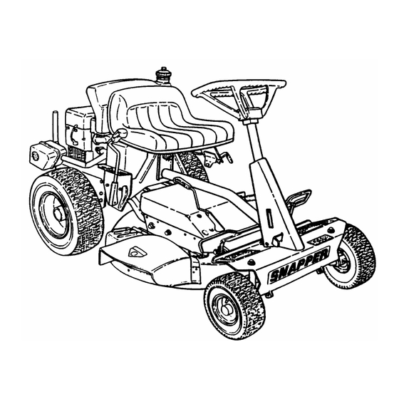
Page 5: Section 1 - Familiarization
This manual has been prepared for the operator’s of the The nomenclature drawing above, Figure 1.1, shows the SNAPPER Rear Engine Rider. Its purpose, aside from essential parts of the SNAPPER Rear Engine Rider. It is recommending standard operating procedures and recommended that all operator’s of this equipment... -
Page 6: Section 2 - Operating Instructions
Section 2 - OPERATING INSTRUCTIONS 2.1 PRE-START CHECK LIST Make the following checks and perform the service OPEN FUEL VENT required before each start-up. FILLER 2.1.1. Check tires and add or release air as needed to bring pressure to 12 psi in front and 12 psi in rear tires. - Page 7 Section 2 - OPERATING INSTRUCTIONS 2.3 STARTING & OPERATION TO START ENGINE, 2.3.1. ENGINE (ELECTRIC START) PUSH CLUTCH/BRAKE IMPORTANT: When the ignition key is turned to PEDAL ALL THE WAY “START”, the engine will turn over, but will not start DOWN unless the Clutch/Brake pedal is pressed all the way down, the Blade Lever is in the “Off”...
- Page 8 Section 2 - OPERATING INSTRUCTIONS 2.3 STARTING & OPERATION 5. Move engine speed control to the choke position 2.3.1. ENGINE (ELECTRIC START) (Continued) to start a cold engine. See Figure 2.6 8. Should the battery be too weak to start the engine, 6.
-
Page 9: Wheel Drive
Refer to Section “BLADE BRAKE ADJUSTMENT” for adjustment procedures or return DEPRESS CLUTCH/BRAKE machine to an authorized SNAPPER dealer for PEDAL adjustment. DO NOT CONTINUE to operate machine until blade brake is adjusted and functioning properly. - Page 10 3 seconds, the blade brake must be adjusted. Refer to Section “BLADE BRAKE ADJUSTMENT” for adjustment procedures or return machine to an authorized SNAPPER dealer for adjustment. DO NOT CONTINUE to operate machine until blade brake is adjusted and functioning properly.
-
Page 11: Parking Brake
Section 2 - OPERATING INSTRUCTIONS 2.4 STOPPING - ENGINE, WHEEL DRIVE, BLADE 2.5. CUTTING HEIGHT ADJUSTMENT 2.4.4. PARK BRAKE 1. Adjust cutting height as desired to any one of 1. Engage park brake by pushing clutch/brake pedal five positions using deck lift lever. Move deck lift lever up or down to desired cutting height and then “DOWN”... -
Page 12: Reverse Lockout Mechanism
Mechanism is not functioning properly. Contact your We realize that this could cause a change to your local Snapper dealer for assistance. previous mowing method but we encourage you to adjust to this new system. Do not defeat the Reverse Lockout Mechanism. -
Page 13: Section 3 - Maintenance Instructions
Remove the battery if the Rear Engine Rider will be the Rear Engine Rider. For the nearest SNAPPER left standing on the rear bumper for longer than 2 dealer in your area, check the yellow pages under the hours. -
Page 14: Check Blade Drive Belt
DO NOT operate machine if interlock system is not Figure 3.4. The belt spacing should be 1 1/4” but no less 1”. If the measurement is less than 1”, the belt functioning properly. Contact your SNAPPER dealer tension should be adjusted. Refer to Section “MOWER immediately for assistance. -
Page 15: Lubrication - Grease Fittings
Section 3 - MAINTENANCE 3.2.9. LUBRICATION – GREASE FITTINGS IMPORTANT: If the Rear Engine Rider will be on its The following components on the Rear Engine Rider are equipped with grease fittings and rear bumper for longer than two hours, remove the require periodic lubrication. -
Page 16: Rear Axle Bearing - Lubrication
CASE differential. If no lubricant is visible on the internal parts of the differential, add “SNAPPER Transmission” grease as needed. See Figure 3.8. IMPORTANT: Overfilling of the differential with lubricant will FILL/LEVEL PLUG P.N. -
Page 17: Service - Annually
Replace worn or damaged parts with FUEL genuine SNAPPER replacement parts available FILLER from an authorized SNAPPER dealer. 3.5.1. All bushings and pivot areas. 3.5.2. Check both front wheel king pins. -
Page 18: Section 4- Adjustments And Repair
However, if there is difficulty in achieving these adjustments and repairs, it is recommended that FIGURE 4.2 these repairs be made by an authorized SNAPPER dealer. 7. Install required number of snap-in frame spacers behind channel pivot until the 1-1/4” distance between WARNING belt is maintained. -
Page 19: Mower Deck Adjustment (Side To Side Levelness)
5. Measure the distance from blade tips to floor. If the described above, take machine immediately to an measurement is within 1/8” from side-to-side, the deck authorized Snapper dealer. attitude is satisfactory. If difference from side-to-side is greater than 1/8”, continue with adjustment. -
Page 20: Mower Deck Adjustment (Front To Rear Levelness)
Section 4 - ADJUSTMENTS & REPAIR WARNING FLOOR DO NOT attempt any adjustments, maintenance, service or repairs with the engine running. Stop engine. Stop blade. Engage parking brake. Remove FRONT REAR key. Remove spark plug wire from spark plug and secure away from plug. -
Page 21: Rear Engine Rider Drive Components
CLUTCH YOKE 4.3 REAR ENGINE RIDER DRIVE COMPONENTS Your Snapper rider is equipped with a patented smooth start clutch. The clutch should operate CABLE smoothly and provide ample traction. If problems are experienced, contact your Snapper dealer for repair. -
Page 22: Mower Blade Replacement
Section 4 - ADJUSTMENTS & REPAIR 5. Inspect condition of blade. See Figure 4.11. WARNING 6. If blade is in good condition, sharpen at 22 to 28 DO NOT attempt any adjustments, maintenance, degrees. DO NOT sharpen beyond existing cutting service or repairs with the engine running. -
Page 23: Blade Drive Belt Removal/Replacement
Section 4 - ADJUSTMENTS & REPAIR 10. Reinstall idler removed in Step 8. The idler belt WARNING guide tab should be positioned in the hole located on DO NOT attempt any adjustments, maintenance, idler arm. Tighten idler pulley bolt securely. service or repairs with the engine running. -
Page 24: Battery Removal, Replacement, Service
Section 4 - ADJUSTMENTS & REPAIR WARNING POSITIVE DO NOT attempt any adjustments, maintenance, TERMINAL INSULATOR POSITIVE (+) service or repairs with the engine running. Stop CABLE engine. Stop blade. Engage parking brake. Remove key. Remove spark plug wire from spark plug and secure away from plug. - Page 25 Section 4 - ADJUSTMENTS & REPAIR WARNING WARNING The electrolyte (acid) produces a highly explosive gas. DO NOT attempt to charge battery while installed on the Keep all sparks, flame and fire away from area when Riding Mower. DO NOT use “BOOST” chargers on the charging battery or when handling electrolyte or battery.
-
Page 26: Accessories
One Ball Floating 0% Charged Less than 1.100 Less than 11.80v Zero Balls Floating SNAPPER REAR ENGINE RIDER ACCESSORIES PART NO. DESCRIPTION OF KIT MODELS USED ON 6-0517........ Wheel Weight (8” Wheels) ....... All Rear Engine Riders 6-0601........ Smooth Start Clutch.......... All Rear Engine Riders 6-0697........ -
Page 27: Troubleshooting
3. Spark plug wire disconnected. 3. Place spark plug wire onto spark plug. Recoil Starter 4. Faulty parking brake, blade or ignition switch. 4. Contact authorized SNAPPER dealer. 5. Park brake not engaged. 5. Engage park brake. 6. Blown Fuse. - Page 28 2. Adjust rubber drive disc. Loss Of Traction drive disc. 3. Tapered axle bolt and nut missing. 3. Replace with SNAPPER tapered bolt & nut. 4. Axle bearing seized. 4. Contact authorized SNAPPER dealer. 5. Insufficient lubrication in chain case or 5.
-
Page 29: Maintenance Schedule
MAINTENANCE SCHEDULE EACH EACH SUBJECT SERVICE REFERENCE HOURS HOURS HOURS HOURS SEASON TO BE PERFORMED PAGES Engine Check Oil Level Page 6 Engine Initial Oil Change Page 13 Engine Periodic Oil Change Page 13 Air Pre-Cleaner Service Sponge Pre- Engine Manual Cleaner Element Air Cleaner Replace Element... -
Page 30: Maintenance/Replacement Parts
MAINTENANCE/REPLACEMENT PARTS MAINTENANCE PARTS Engine Speed Control (Briggs Engine) 2-4155 Clutch/Brake Cable 2-9913 Brake Cable 2-2344 Reverse Lockout Mechanism 7-3216 25” Cutter Blade (Standard - Not Air Lift Compatible) 3-5619 25” Cutter Blade (Standard - Air Lift Compatible) 1-9518 25” Cutter Blade (Mulching) 1-6967 25”... -
Page 31: Warranty
For three (3) years from purchase date for the original purchaser's residential, non-commercial use, SNAPPER, through any authorized SNAPPER dealer will replace, free of charge (except for taxes where applicable), any part or parts found upon examination by the factory at McDonough, Georgia, to be defective in material or workmanship or both. -
Page 32: Primary Maintenance
PRIMARY MAINTENANCE... - Page 33 PRIMARY MAINTENANCE...
- Page 34 PRIMARY MAINTENANCE...
- Page 35 PRIMARY MAINTENANCE...
- Page 36 Read, Understand, and Follow all warnings and instructions in this manual, the engine manual, and on the machine, engine and attachments. If you have any questions about your Snapper product, contact your local authorized Snapper dealer or contact Snapper Customer Service at Snapper, McDonough, GA.
Need help?
Do you have a question about the 21 Series and is the answer not in the manual?
Questions and answers