Table of Contents
Advertisement
Quick Links
Federal Communications Commission (FCC) Statement
This equipment has been tested and found to comply with the limits for a Class B digital
device, pursuant to Part 15 of FCC Rules. These limits are designed to provide reasonable
protection against harmful interference in a residential installation. This equipment
generates, uses and can radiate radio frequency energy and, if not installed and used in
accordance with instructions contained in this manual, may cause harmful interference
to radio and television communications. However, there is no guarantee that interference
will not occur in a particular installation.
If this equipment does cause harmful interference to radio or television reception, which
can be determined by turning the equipment off and on, the user is encouraged to try to
correct the interference by one or more of the following measures:
-
REORIENT OR RELOCATE THE RECEIVING ANTENNA
-
INCREASE THE SEPARATION BETWEEN THE EQUIPMENT AND THE RECEIVER
-
CONNECT THE EQUIPMENT INTO AN OUTLET ON A CIRCUIT DIFFERENT FROM
THAT OF THE RECEIVER
-
CONSULT THE DEALER OR AN EXPERIENCED AUDIO/TELEVISION TECHNICIAN
NOTE: Connecting this device to peripheral devices that do not comply with Class B
requirements, or using an unshielded peripheral data cable, could also result
in harmful interference to radio or television reception.
The user is cautioned that any changes or modifications not expressly approved
by the party responsible for compliance could void the user's authority to
operate this equipment.
To ensure that the use of this product does not contribute to interference, it is
necessary to use shielded I/O cables.
Copyright
This manual is copyrighted with all rights reserved. No portion of this manual may be copied or
reproduced by any means.
While every precaution has been taken in the preparation of this manual, no responsibility for errors
or omissions is assumed. Neither is any liability assumed for damages resulting from the use of the
information contained herein.
Trademarks
All brand names, logos and registered trademarks mentioned are property of their respective owners.
Electronic Emission Notices
1
Advertisement
Table of Contents

Related Manuals for PC Partner LXA826D


Summary of Contents for PC Partner LXA826D
- Page 1 Electronic Emission Notices Federal Communications Commission (FCC) Statement This equipment has been tested and found to comply with the limits for a Class B digital device, pursuant to Part 15 of FCC Rules. These limits are designed to provide reasonable protection against harmful interference in a residential installation.
-
Page 2: Table Of Contents
Table of Contents HARDWARE CONFIGURATION .............. 3 Key Features ....................3 Motherboard Layout (Model Code No. - 35880201/35880202) ....5 Hardware Setting ..................6 CPU Speed Selection ................6 JP4 - CMOS Clear .................. 6 JP16 - Keyboard Power on Password Clear ........6 JP8, JP23 - PNP BIOS Program Voltage .......... -
Page 3: Hardware Configuration
HARDWARE CONFIGURATION The Pentium® II Micro ATX motherboard is based on the Intel® 440EX/440LX Chipset. The chipset is a highly integrated solution for a cost-effective and compact motherboard. The motherboard supports SDRAM and 3.3V EDO. Features on-board include super-I/O, Ultra DMA33, PCI bus master IDE, AGP Ver 1.0, PCI Ver 2.1 compliant, USB, VRM 8.1 compliant, ECC (440LX ver. - Page 4 On-Board I/O • On board two PCI fast IDE ports supporting up to 4 ATA, ATA2 and Ultra DMA33 IDE HDDs, CD-ROMs, ZIP drives and LS-120 drives as boot drive. • Support Bus Master IDE and PIO mode 4 (up to 22M bytes/sec) and Ultra DMA33 (up to 33M bytes/sec) transfer.
-
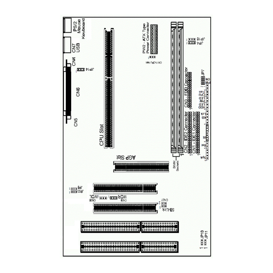
Page 5: Motherboard Layout (Model Code No. - 35880201/35880202)
Motherboard Layout (Model Code No. - 35880201/35880202) The following diagrams show the relative positions of the jumpers, connectors, major components and banks on the motherboard. Hardware Setup... -
Page 6: Hardware Setting
Hardware Setting This chapter explains how to configure the motherboard’s hardware. Before using your computer, make sure all jumpers and DRAM modules are set correctly. Refer to this chapter whenever in doubt. CPU Speed Selection In this motherboard, jumperless feature is implemented such that no jumper is required to be set for different type of CPU installed. -
Page 7: Jp8, Jp23 - Pnp Bios Program Voltage
JP14 - Keyboard Power Select JP14 Selection Powered by +5V 2-3* Powered by +5V Standby (Allows Keyboard Power ON) Keyboard Password Power ON This motherboard provides a special security feature of keyboard password power on. The feature is enabled in integrated peripherals menu of CMOS setup. -
Page 8: Installation
Installation Installing the Retention Mechanism To install the retention mechanism, follow these steps: 1. Locate Slot 1 and the four attachment studs on the motherboard. 2. To position the mechanism, orient it as shown in figure. The tab on the connector fits into a notch in the base of the mechanism. -
Page 9: Installing The Dimms
Installing the DIMMs 1. Turn off all peripheral devices connected to the computer. Turn off the computer. 2. Remove the computer cover and locate the DIMM sockets. 3. Holding the DIMM by the edges, remove it from its antistatic package. 4. -
Page 10: Bios Setup
BIOS SETUP This chapter discusses Award’s Setup Program built into the ROM BIOS. The Setup Program allows users to modify the basic system configuration. This special information is then stored in battery-backed RAM, which retains the setup information when the power is turned off. -
Page 11: Standard Cmos Setup
ROM PCI/ISA BIOS CMOS SETUP UTILITY AWARD SOFTWARE. INC. STANDARD CMOS SETUP CPU SPEED SETTING BIOS FEATURES SETUP INTEGRATED PERIPHERALS CHIPSET FEATURES SETUP SUPERVISOR PASSWORD POWER MANAGEMENT SETUP USER PASSWORD PNP/PCI CONFIGURATION SETUP IDE HDD AUTO DETECTION LOAD BIOS DEFAULTS SAVE &... - Page 12 Integrated This section page includes all the items of IDE hard drive Peripherals and Programmed Input / Output features. Supervisor / Changes, sets, or disables password. It allows you to limit access User Password to the system and the Setup Program. Setting IDE HDD Auto Automatically detects and configures the hard disk parameters.
-
Page 13: Bios Features Setup
Primary These categories identify the types of the two channels that Master/Primary have been installed in the computer. There are 45 predefined Slave/Secondary types and one user definable types in BIOS. Type 1 to Type 45 are Master/Secondary predefined. Type “user” is user-definable. Slave Press PgUp or PgDn to select a numbered hard disk type or type the number and press <Enter>. -
Page 14: Chipset Features Setup
Chipset Features Setup The Chipset Features Setup option is used to change the values of the chipset registers. These registers control most of the system options in the computer. This section allows you to configure the system based on the specific features of the installed chipset. - Page 15 PASSWORD DISABLED. Once the password is disabled , the system will reset and you can enter the Setup Program freely. When a password is enabled, you will be prompted to enter it every time you try to enter setup. This prevents an unauthorized person from changing any setting of your system configuration.
-
Page 16: Flash Update Procedure
Flash Update Procedure A program AWDFLASH.EXE is included in the utility diskette. The user is recommended to follow the procedure below to update the flash BIOS. 1. Create a DOS-bootable floppy diskette. Copy the new BIOS file (just obtained or downloaded) and the utility program AWDFLASH.EXE to the diskette.
Need help?
Do you have a question about the LXA826D and is the answer not in the manual?
Questions and answers