
Summary of Contents for catec ZOGLAB HG6000
- Page 1 MEETINSTRUMENTATIE ZOGLAB Turfschipper 114 | 2292 JB Wateringen | Tel. +31 (0)174 272330 | www.catec.nl | info@catec.nl HG6000 Humidity Generator User Manual...
- Page 3 Limited Warranty And Limited Liability We guarantee that ZOGLAB products will be free of defects in materials and workmanship within one year from the date of purchase. This warranty does not cover fuses, disposable batteries, or products damages from accident, negligence, misuse, or abnormal use or handling. ZOGLAB has not authorized any distributor to extend the warranty period.
-
Page 5: Table Of Contents
Contents CHAPTER 1 Safe Usage Instruction Safe Usage Instruction ----------------------------------------------------------- CHAPTER 2 HG6000 Product Introduction About HG6000 ------------------------------------------------------------------ Structure view and function description -------------------------------------------- Front view ---------------------------------------------------------------------- Function description ------------------------------------------------------------- Interface definition of test instrument ---------------------------------------------- Rear and side view --------------------------------------------------------------- Function description -------------------------------------------------------------... - Page 6 Value setting numeric soft keyboard icon ----------------------------------------- 14 Status/setting interface icon ---------------------------------------------------- CHAPTER 3 Operation and Usage Connect power supply ----------------------------------------------------------- 17 Connect external expansion test cabin interface ---------------------------------- Add/Drain water --------------------------------------------------------------- Add desiccant ------------------------------------------------------------------ Power on/off ------------------------------------------------------------------ Insert the humidity probe -------------------------------------------------------- Set temperature ---------------------------------------------------------------...
- Page 7 Calibration setting -------------------------------------------------------------- 31 Control setting ---------------------------------------------------------------- Store recording ---------------------------------------------------------------- Time setting ------------------------------------------------------------------ Brightness setting -------------------------------------------------------------- Sound setting ----------------------------------------------------------------- Language setting -------------------------------------------------------------- System information ------------------------------------------------------------ System update ---------------------------------------------------------------- Help -------------------------------------------------------------------------- CHAPTER5 HG6000 Product Information Technical specification --------------------------------------------------------- Product dimensions ------------------------------------------------------------ Packing list -------------------------------------------------------------------- Quality certification...
- Page 8 Appendix Communication protocol HG6000 common problem troubleshooting table...
-
Page 9: Chapter 1 Safe Usage Instruction
CHAPTER 1 Safe Usage Instruction... -
Page 10: Safe Usage Instruction
CHAPTER 1 Safe Usage Instruction Safe Usage Instruction The HG6000 humidity generator is a precision instrument. Safety precautions must be observed during all stages of using this instrument. The company shall not be liable for any abnormal operation, damage or indirect economic losses caused by failure to observe these safety measures or other warnings or instructions in this manual. - Page 11 CHAPTER 1 Safe Usage Instruction Don ' t remove the housing Only qualified, maintenance-trained professionals who understand the potential hazards can open the housing. Before removing the housing, be sure to disconnect the power supply and external circuits. Don ' t adjust the instrument Professional maintenance personnel not belonging to or authorized by our company are not allowed to repair, modify with substitute parts or adjust the instrument by themselves.
-
Page 12: Chapter 2 Hg6000 Product Introduction
CHAPTER 2 HG6000 Product Introduction... -
Page 13: About Hg6000
CHAPTER 1 Safe Usage Instruction About HG6000 HG6000 is a dual-flow humidity generator. Based on semiconductor constant temperature technology, various humidity environments can be generated within a set temperature range. Built-in circulation pump and stirring fan can quickly respond to the set humidity value. The stabilization time is less than 10 minutes, and the calibration and verification can be completed in a short time. -
Page 14: Structure View And Function Description
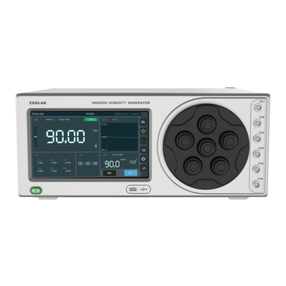
CHAPTER 2 HG6000 Product Introduction Structure view and function description Front view ① ② ⑥ ⑤ ④ ③... -
Page 15: Function Description
CHAPTER 2 HG6000 Product Introduction Function description View ID No. Part name Function description ① LCD display Main working screen, touch operation interface ② Interface area of test instrument Data communication/signal collection ③ Dimension of verification window probe Standard version compatible with ø12~19mm ④... -
Page 16: Rear And Side View
CHAPTER 2 HG6000 Product Introduction Rear and side view ① ② ③ ④ ⑤ ⑥ ⑦⑧ ⑨... -
Page 17: Function Description
CHAPTER 2 HG6000 Product Introduction Function description View NO. Part name Function description ① Power switch Switch “-”to turn on; switch to“O”to turn off ② Power connection Connect power cable ③ Vents Used for cooling ④ External expansion test cabin interface Used to expand the test cabin to adapt to special needs ⑤... -
Page 18: Display Icon And Function Description
CHAPTER 2 HG6000 Product Introduction Display icon and function description Main interface icon Device information bar Standard display area Curve interface display area Signal display area Set value display area of the test instrument Shortcut operation area Status display area Functional operation area... -
Page 19: Main Interface Function Description
CHAPTER 2 HG6000 Product Introduction Main interface function description Part name Function description Display brand, instrument name, current year, month, day and time, etc. Device information bar Curve interface display area Display humidity and temperature curves Set value display area Display control humidity and temperature target value;... -
Page 20: Humidity Measurement Icon And Description
CHAPTER 2 HG6000 Product Introduction Humidity measurement icon and description Temperature measurement Stable state reminder Curve interface display Control status display Standard measurement value Liquid level display Part name Function description Temperature measurement Display the humidity value measured by the instrument Stable state reminder The color of the value turns green to indicate stable state Curve interface display... -
Page 21: Measurement Function Icon And Description
CHAPTER 2 HG6000 Product Introduction Measurement function icon and description Temperature setting Humidity setting Signal display area of the Measuring stabilization time Programming Start/Stop test instrument Function description Part name Temperature setting Display the set temperature value, click to set Temperature setting Display the set humidity value, click to set Start/Stop... -
Page 22: Value Setting Numeric Soft Keyboard Icon
CHAPTER 2 HG6000 Product Introduction Value setting numeric soft keyboard icon Set value upper and lower limits Range: 5~95 Return key Number key Delete key Enter Part name Function description Set value upper and lower limits Display the upper and lower limits of humidity. Cannot enter a value beyond the limits Number key Input number Return key... -
Page 23: Status/Setting Interface Icon
CHAPTER 2 HG6000 Product Introduction Status/setting interface icon When running, the status bar displays the stabilization time; the set value display area displays the set humidity value and temperature value Set value display area Status display area Programming Start/Stop Part name Function description Status display area Display equipment stabilization time... -
Page 24: Chapter 3 Operation And Usage
CHAPTER 3 Operation and Usage... -
Page 25: Connect Power Supply
CHAPTER 2 HG6000 Product Introduction Connect power supply Connect the power cable to the power port on the rear panel of the HG6000, and connect the other end of the power cable to a 100~240VAC, 50/60Hz power supply. Connect the power cable Before connecting the power cable, make sure that the power switch is switched to the "O"... -
Page 26: Connect External Expansion Test Cabin Interface
CHAPTER 3 Operation and Usage Connect external expansion test cabin interface When there is no external test chamber, the INPUT and OUTPUT ports of the extended test chamber need to be connected with an outer diameter 8mm PU pipe... -
Page 27: Add/Drain Water
CHAPTER 3 Operation and Usage Add/Drain water Use a PU pipe with an outer diameter of 8mm, put one end of the water pipe into a container with distilled water, and put the other end into the "add/drain" port. On the main operating interface, click the "liquid level display" icon to automatically add water from the "add/drain"... -
Page 28: Add Desiccant
CHAPTER 3 Operation and Usage Add desiccant Grasp the drying compartment cover, then turn it counterclockwise to open the drying compartment cover, take out the drying cylinder and unscrew the drying cylinder cover at one end, add/replace the desiccant. After replacement, put it back in the drying compartment, and turn the cover of the drying compartment clockwise. Open the drying cylinder cover and replace the desiccant Turn counterclockwise to open the drying hatch... -
Page 29: Power On/Off
CHAPTER 3 Operation and Usage Power on / off Switch the power switch on the rear panel to "-" (power on) state, press the power button on the panel, the HG6000 will be turned on after the buzzer beeps, and enter the initialization self-check.The main work screen will be on. In the power-on state, press the power button on the front panel to shut down. -
Page 30: Insert The Humidity Probe
CHAPTER 3 Operation and Usage Insert the humidity probe to be tested Remove the plug of the test chamber and insert the humidity probe for testing. If the probe needs additional power supply and communication, you can use the interface of the test instrument on the panel. Please refer to page 7 for the interface wiring definition of the test instrument. -
Page 31: Set Temperature
CHAPTER 3 Operation and Usage Humidity setting Set the humidity target value. Please input the target value according to the effective range of the instrument. Take the control range of 5~95%RH as an example. If the input target value exceeds the valid range, it is an invalid operation. Target value input method: Click on the "humidity value"... -
Page 32: Operating
CHAPTER 3 Operation and Usage Operation Click the "Start" button on the screen, the measured value display area displays the measured humidity inside the instrument. When the value in the numerical display area is close to the target value and the status cursor bar turns green, it indicates that the humidity has stabilized. -
Page 33: Programming
CHAPTER 3 Operation and Usage Programming Click the "Program" button on the interface of the function operation area to enter the programming mode interface. Multiple control points can be edited as needed to automatically control the output. This interface can view and set the temperature value, humidity value and stabilization time. Example: Click the "Humidity Value"... -
Page 34: Test Probe Measurement
CHAPTER 3 Operation and Usage Test probe measurement Probe measurement Click the value on the interface of the signal display area of the test instrument in the lower part of the interface, and the selection interface pops up. Choose a different temperature and humidity probe communication protocol or analog signal definition as needed, and then click "Exit"... -
Page 35: Chapter 4 System Settings
CHAPTER 4 System Settings... -
Page 36: System Setting Interface
CHAPTER 4 System Setting System setting interface Click ‘setting’ button on the right side of the main working interface to enter the system setting interface. System settings include network, serial port, calibration, control, storage, time, brightness, sound, language, information, upgrade, and help. Click ‘Exit’ button to return to the main working interface. Setting Main interface of system settings... -
Page 37: Network Setting
CHAPTER 4 System Setting Network setting Click the system setting interface button to enter the network settings interface. Through the numeric soft keyboard, enter the IP address, subnet mask and default gateway. Click the ‘OK’ button to save the network settings and return to the system settings interface. -
Page 38: Com Setting
CHAPTER 4 System Setting COM setting Click the system setting interface button to enter the COM setting interface. Set the baud rate, parity bit, data bit and stop bit by clicking the dot icon in front of the parameter. If there is no need to change, click the ‘Exit’... -
Page 39: Calibration Setting
CHAPTER 4 System Setting Calibration setting Click the system setting interface button to enter the calibration management interface. The HG6000 can be calibrated for humidity, voltage and current. Click the "Exit" button to return to the system setting interface. Calibration management interface... -
Page 40: Control Setting
CHAPTER 4 System Setting Control setting Click the system setting interface button to enter the control parameter setting interface (password required). After editing the control parameters, click the "Exit" button to save and return to the control parameter setting interface, and return to the control parameter setting interface. -
Page 41: Store Recording
CHAPTER 4 System Setting Store records Click the system setting interface button to enter the storage management interface. Can read and set the data record status, click the "Exit" button to return to the system setting interface. Storage management interface... -
Page 42: Time Setting
CHAPTER 4 System Setting Time setting Click the system setting interface button to enter the time setting interface. Through the numeric soft keyboard, modify the year, month, day and time displayed on the screen. Click "Exit" to save the changes and return to the system setting interface. Time setting interface... -
Page 43: Brightness Setting
CHAPTER 4 System Setting Brightness setting Click the system setting interface button to enter the brightness setting interface. Slide the triangle icon on the interface to change the backlight brightness of the screen. The higher the brightness percentage, the brighter the screen backlight. Click the "Exit"... -
Page 44: Sound Setting
CHAPTER 4 System Setting Sound setting Click the system setting interface button to enter the sound setting interface. Click the square icon in front of the option to set the key tone and alarm tone. Highlight the "√" symbol in the icon to turn on the option prompt. Click the "Exit" button to return to the system setting interface. -
Page 45: Language Setting
CHAPTER 4 System Setting Language setting Click the system setting interface button to enter the language setting interface. Click the round icon in front of the option to select the language. If there is no need to change, click the "Exit" button to return to the system setting interface. Language settings interface... -
Page 46: System Information
CHAPTER 4 System Setting System information Click the button of the system setting interface to check the system information. Click the "Exit" button to return to the system setting interface. System information interface... -
Page 47: System Update
CHAPTER 4 System Setting System update Click the system setting interface button to enter the system update interface to update the system files and control system. The system update requires the supplier to provide the corresponding update file. If the file does not exist, the update will not be possible. -
Page 48: Help
CHAPTER 4 System Setting Help Click the button of the system setting interface, if you have any questions, please consult the free hotline: +86-400-8878-571 Help interface... -
Page 49: Chapter5 Hg6000 Product Information
CHAPTER 5 HG6000 Product Information... -
Page 50: Technical Specification
CHAPTER5 HG6000 Product Information Technical specification Humidity control range 5~95%RH Temperature control range 5~50℃ ± Humidity control stability ℃ ℃ , ℃ Temperature control stability (Full scale) Temperature accuracy ≤0.2℃ ±1.0%RH(10~90%RH);±2.0%RH(≤10,≥90%RH) Humidity accuracy of standard probe(23℃) Temperature and humidity stability ±0.2%RH;±0.1℃... - Page 51 CHAPTER5 HG6000 Product Information Φ96×120mm Dimensions of the verification chamber Φ12-19mm,Special size is optional Dimensions of the Window -10~40℃,10%~95%RH(No condensation) Operating environment -20~70℃,10%~95%RH(No condensation) Storage environment Desiccant Molecular sieve desiccant Display screen 9inch 1024 600TFT LCD display , × 100~240VAC 1.5A,50/60Hz Power supply RS485/232,USB,LAN,Wi-Fi* Communication Interface...
-
Page 52: Product Dimensions
CHAPTER5 HG6000 Product Information Dimensions(mm) -
Page 53: Packing List
CHAPTER5 HG6000 Product Information Packing list Please confirm the following items should be in the package: HG6000 humidity generator USB communication cable LAN communication cable Power cable Rs232 communication cable... - Page 54 CHAPTER5 HG6000 Product Information Working hatch* (optional) Φ15~18×6 Φ12~15 ×5 Transparent acrylic Φ12~18+Φ30mm Φ30×2 Calibration certificate For HC2-S cover For DSP2000 dew For DSP2000 dew point sensor point sensor ZOGLAB ZOGLAB ZOGLAB 合格证 HG6000 湿度发生器用户手册 保修卡 Qualification Warranty Card 维修手册 仪器名称...
-
Page 55: Quality Certification
CHAPTER5 HG6000 Product Information Quality certification HG6000 has multiple international patents, and has obtained CE certification, FCC certification, C-TIC certification, VCCI certification. HG6000 is tested and certified by the world renowned certification agency SGS. -
Page 56: Chapter6 Service
CHAPTER 6 Service... -
Page 57: Warranty
CHAPTER 6 Service Warranty Thank you for choosing our products. In order to protect your legal rights, please read the following warranty terms carefully after getting the product. This product has a one-year warranty service for the host and one year for accessories after purchase. - Page 58 Appendix I Communication protocol Description Function Command Return Information AT*TakeInfo AT*TakeInfo DeviceID: HG6000S20200723002A Serial number Manufacturer: ZOGLAB Microsystem Co.,Ltd Manufacturer Ver: 1.10, 1.11 Hardware and software version Reboot AT^Reboot AT^Reboot the system AT*ReadSensor:0 AT*ReadSensor:0 Read temperature T= 19.99℃ RH= 49.98%RH OK!...
- Page 59 Description Function Command Return AT+SetHumi:50.0 AT+SetHumi:50.0 (5-95) 5-95%RH Set humidity Read humidity AT*ReadSetPoint:0 AT*ReadSetPoint set value SetPoint:95.00 %RH 1 stable, 0 unstable Read stabilization AT*ReadStable:0 AT*ReadStable state Stable:1...
- Page 60 Description Function Command Return Set backlight AT+SetLight=(1-8) AT+SetLight 1-8 level brightness brightness Read the AT*ReadLight AT+ReadLight backlight LcdBackLight:6 brightness Set system time AT+RTC=20-12-03 15:09:30 AT+SetTime AT*RTC AT*ReadTime Read system time System time 2020-12-03 15:09:31 Time:20-12-03 15:09:43...
- Page 61 Description Function Command Return AT+SetIPAddr=192.168.0.100 AT+SetIPAddr Set IP address Set IP address AT*ReadIPAddr AT*ReadIPAddr IPAddr:192.168.0.100 IP address Set the gateway AT+SetGateWay=192.168.0.1 AT+SetGateWay AT*ReadGateWay AT*ReadGateWay Read gateway GateWay:192.168.0.1 gateway...
- Page 62 Description Function Command Return Set the subnet AT+SetNetMask=255.255.255.0 AT+SetNetMask mask Read the AT*ReadNetMask AT*ReadNetMask subnet mask NetMask:255.255.255.0 Subnet mask Set DNS AT+SetDNS=202.101.172.35 AT+SetDNS Read DNS AT*ReadDNS AT*ReadDNS DNS:202.101.172.35...
- Page 63 Appendix II Common problem troubleshooting table Common problems Solutions Unable to start The fuse is burned out, replace fuse The screen is dim Enter the system settings, adjust the backlight brightness of the screen Low humidity can’t be The desiccant is invalid, please replace the desiccant in time reached for a long time High humidity can’t be The water tank is short of water, please add water;...
Need help?
Do you have a question about the ZOGLAB HG6000 and is the answer not in the manual?
Questions and answers