
Related Manuals for Berthold LB 917


Summary of Contents for Berthold LB 917
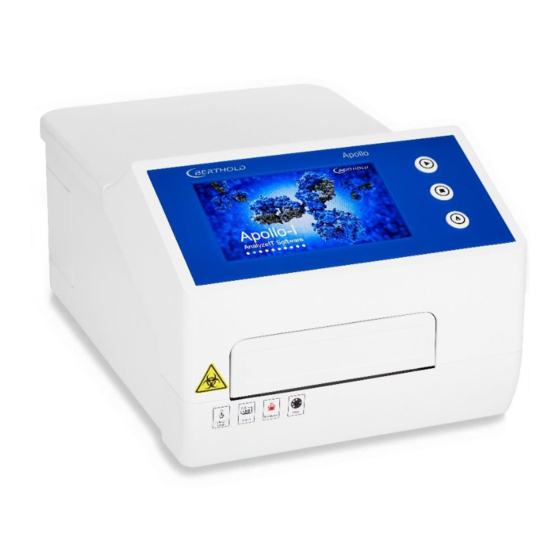
- Page 1 Apollo / Apollo-I Microplate Absorbance Reader LB 917 Operating Manual 73664BA2 Rev. No.: 00, 05/2022...
- Page 3 The information in this guide is subject to change without notice. DISCLAIMER TO THE EXTENT ALLOWED BY LAW, BERTHOLD TECHNOLOGIES AND/OR ITS AFFILIATE(S) WILL NOT BE LIABLE FOR SPECIAL, INCIDENTAL, INDIRECT, PUNITIVE, MULTIPLE, OR CONSEQUENTIAL DAMAGES IN CONNECTION WITH OR ARISING FROM THIS DOCUMENT, INCLUDING YOUR USE OF IT.
-
Page 5: Table Of Contents
LB 917 Apollo/Apollo-I Table of Contents Table of Contents Prefatory Comments ......................7 Contact Information ........................7 The Operating Manual ........................ 7 Typographical Conventions ......................8 1.3.1 Symbols on the instrument ......................8 Warnings, Notes and Symbols used in this Manual ..............8 1.3.2... - Page 6 Warranty and Technical Issues .................... 55 Special spare parts ........................55 14.1 14.2 Warranty statement ......................... 55 14.3 Customer service ........................55 Return Shipment to Berthold Technologies ................56 14.4 Index ........................... 57 6 of 58 73664BA2 Rev. 00, 05/2022...
-
Page 7: Prefatory Comments
E-Mail: service@berthold.com The Operating Manual This operation manual is valid for both, LB 917 Apollo and LB 917 Apollo-I (with heating) from the delivery of the Berthold product to the user until its disposal. Version and release date of this operating manual can be found in the bottom of each page. -
Page 8: Typographical Conventions
No domestic waste. The electronic product must not be disposed of in do- mestic waste. Depending on the instrument configuration (with/without incubator) additional informative la- bels are located below the front door. Example for LB 917 Apollo-I: Warnings, Notes and Symbols used in this Manual 1.3.2 CAUTION Refers to a potentially dangerous situation, which can result in medium or minor physical injuries or damages to property, if it is not avoided. -
Page 9: Connections At The Instrument
1 Prefatory Comments Connections at the instrument LB 917 is equipped with a USB port, a COM port and a LAN port, as well as a Print port at the right side of the cover. The power socket is located at the rear side. -
Page 10: Important Information
The device is for use in scientific research, food and environmental research or agriculture. CAUTION LB 917 Apollo /Apollo-I must not be used for in vitro diagnostics. LB 917 Apollo/Apollo-I must not be used for any other purpose than those described in this manual. Safety Instructions and Precautions... - Page 11 See chapter12. • Berthold Technologies assumes no liability for any damages, including those to third parties, caused by improper installation, use or handling of the device. The instruments are live and improper handling may cause damage.
-
Page 12: Consignes De Sécurité
• Only parts specified by Berthold Technologies may be used for maintenance and ser- vice. • Always disconnect the plug before opening the device for service or modifications. - Page 13 • L'utilisateur ne doit pas ouvrir ou réparer l'instrument par lui-même. N'arrachez aucune vis ou pièce. Cela pourrait endommager l'instrument et annulerait la garantie. Si une réparation est nécessaire, contactez le service après-vente de Berthold Technologies ou votre distributeur local.
-
Page 14: Sicherheitshinweise
Berthold Technologies. Avant toute nouvelle utilisation, l'instrument doit être remonté et inspecté conformément aux instructions du manuel d'entretien. • Seules les pièces spécifiées par Berthold Technologies peuvent être utilisées pour l'en- tretien et le service. • Débranchez toujours la fiche avant d'ouvrir l'appareil pour l'entretien ou les modifica- tions. - Page 15 LB 917 Apollo/Apollo-I 2 Important Information • Berthold Technologies übernimmt keine Haftung für Schäden, auch nicht gegenüber Dritten, die durch unsachgemäße Installation, Verwendung oder Handhabung des Ge- räts entstehen. Die Geräte stehen unter Spannung und eine unsachgemäße Handhabung kann zu Schäden führen.
-
Page 16: Further Instructions
Gerät gemäß den Anweisungen in der Serviceanleitung wieder zusammengebaut und überprüft werden. • Für Wartung und Service dürfen nur von Berthold Technologies spezifizierte Teile ver- wendet werden. • Ziehen Sie immer den Netzstecker, bevor Sie das Gerät für Servicearbeiten oder Ände- rungen öffnen. -
Page 17: General Description
LB 917 Apollo/Apollo-I 3 General description General description The Apollo/Apollo-I microplate reader measures absorbance in colorimetric Immuno Assays. The measurements are performed in 96 well microplates. Measurements can be performed using onboard software on the device. Features and Benefits • Easy to use: 7 ‘’ color touch screen and 3 external keys. - Page 18 3 General description LB 917 Apollo/Apollo-I Rear panel door USB and print port Rear doorknob COM port Power inlet and LAN port main switch Scheme: Side and rear view Function Control button Start, Stop and Plate in/out Plate holder Carries a 96 well microplate...
-
Page 19: Getting Started
LB 917 Apollo/Apollo-I 4 Getting Started Getting Started Unpacking Each Apollo/Apollo-I is thoroughly tested before shipping. Please check the package again when you receive the instrument and contact your local distributor or manufacturer if: • The outer package is damaged •... -
Page 20: General Operation
General Operation IMPORTANT This software description is valid for both, LB 917 Apollo and LB 917 Apollo-I (with heating function). The Apollo-I screenshots show a heating symbol in the lower right corner, but are otherwise identical to those of the Apollo without heating. -
Page 21: File Management
LB 917 Apollo/Apollo-I 5 General Operation File Management 5.2.1 The upper left box shows the current [protocol name]. As shown in Fig. 2 the current default protocol is Demo_1. • Click <New> to create a new protocol. Input the new protocol name, click <Enter>... - Page 22 5 General Operation LB 917 Apollo/Apollo-I Fig 5: Submenu Batch OP • Click <Delete> to delete the chosen protocol file (Fig 7) in the internal memory. A warn- ing message will appear. Protocol files on a USB stick cannot be deleted using the instrument.
-
Page 23: Function Keys
LB 917 Apollo/Apollo-I 5 General Operation Function Keys 5.2.2 Actions can be started by use of the function keys on the [Protocol] main screen (Fig 2). Fig 2: Protocol main screen • Click the <Start> button to start a protocol. - Page 24 5 General Operation LB 917 Apollo/Apollo-I Fig 10: Enter the results file name During a reading, a dialog box will indicate [measuring now], and all buttons are disa- bled, except for <Stop> which can be used to interrupt the measurement.
-
Page 25: Setup A Protocol
Filter 1 wavelength. Select the filter wavelength needed. See Fig 13. Fig 13: Filter 1 settings LB 917 can measure at a single wavelength or at two wavelengths. Set <Filter 2> to <Off> in case of a single wavelength measurement. - Page 26 6 Setup a protocol LB 917 Apollo/Apollo-I If a second wavelength measurement is desired, define Filter 2 settings. Click on the right side of <Filter2> and select a second wavelength, different from that of Filter 1. See Fig 14. Fig 14: Filter 2 settings To define the measurement speed, click on the right side of <Mode>...
-
Page 27: Define The Layout
LB 917 Apollo/Apollo-I 6 Setup a protocol Define the Layout Plate Layout 6.2.1 Press <Layout> to set the layout of the sample plate. You will find an area for plate lay- out definition, available <Sample types> and the buttons <Concentration>, <Delete all>, <OK>... -
Page 28: Define Standard Concentrations
6 Setup a protocol LB 917 Apollo/Apollo-I Fig 17: Menu of the number of standards Fig 18: Menu of the number of Quality control samples In case of standard samples, it is necessary to input the standard sample concentrations before starting a measurement. Go on with chapter 6.2.2. - Page 29 LB 917 Apollo/Apollo-I 6 Setup a protocol Set the concentration for the standard positions that have been defined in the layout. The ones which have not been set in the layout will not be considered. Click the concentration number twice to input the concentration value. Confirm your input with <Enter>.
-
Page 30: Define Shake Settings
6 Setup a protocol LB 917 Apollo/Apollo-I Define shake settings Shaking of the sample plate mixes the samples and helps the settlement of liquid samples on the bottom of the wells. Click <Shake> on the [Protocol] main screen to enter the [Shaking parameters] inter- face. -
Page 31: Calculations
LB 917 Apollo/Apollo-I 6 Setup a protocol Click <Time> to define the shaking time. The number must be set as hh/mm/ss. Fig 25: Shaking time setting Set the shaking <Mode>. There are two setting: <First> and <Each>. Choose <First> to shake only before the first reading in a multiple reading. - Page 32 6 Setup a protocol LB 917 Apollo/Apollo-I Fig 26: Calculation parameters Click the <interval> button to set the interval between the readings. The format is hh:mm:ss. Click the <Para> button on the right side of the screen and open the kinetic parameter submenu.
- Page 33 LB 917 Apollo/Apollo-I 6 Setup a protocol Type Description <Time to change> Calculates the time required to reach a defined change in the signal (in each well). The three parameters at right are active. See Fig 28. Baseline Select: The baseline parameter is the number of in- itial readings that are used for the baseline calculation.
-
Page 34: Preprocess Calculation
6 Setup a protocol LB 917 Apollo/Apollo-I Preprocess calculation 6.4.2 IMPORTANT This submenu is for double wavelength measurement only. The two wavelength measurements M1 and M2 can be charged differently. See Fig 29. Click on the right side of the <Preprocess> button in the [Calculate parameters] inter- face. -
Page 35: Interpret
LB 917 Apollo/Apollo-I 6 Setup a protocol Interpret IMPORTANT This menu is for definition of assays using positive and negative controls for calculation of Cut-off thresholds (qualitative analysis). See Fig 2: [Protocol] main interface. Click <Interpret> on the [Protocol] interface to enter the submenu [Interpretation] for qualitative analysis. -
Page 36: Quality Control
6 Setup a protocol LB 917 Apollo/Apollo-I Quality Control See Fig 2: [Protocol] main interface and click <Quality> to enter the submenu for quality control. See Fig 32. Fig 32: Quality control Click <Abs> or <Conc.> as quality control variable. -
Page 37: Incubator Settings (Apollo-I Only)
LB 917 Apollo/Apollo-I 6 Setup a protocol Incubator settings (Apollo-I only) Click into the lower right corner of the protocol interface, showing the incubator status (usually set to <Off>), to enter the incubator setting interface. See Fig 34 Set incubation <On>. -
Page 38: Results
7 Results LB 917 Apollo/Apollo-I Results This interface shows the measurement results. Measurements are performed in the [Protocol] interface. After measurement, the display will switch to the [Results] interface automatically, showing the current measurement results. Alternatively you can view results by clicking the [Results] tab at the top of the screen. -
Page 39: Interpret Results
LB 917 Apollo/Apollo-I 7 Results Click <Export>. Kinetic reading data are exported in .csv-file format with individual rows including the full set of data of all wells. This allows the user to select rows of data and create graphs. Fig 37: Export settings for qualitative analysis (example) If a thermal printer is connected (optional), click <Print>... -
Page 40: Analysis
7 Results LB 917 Apollo/Apollo-I Analysis 7.1.3 This submenu is for quantitative analysis. It is used for calculation of concentrations using the correlation of absorbance to concentration as it has been established by the standard settings and the curve fit. -
Page 41: Qc Results
LB 917 Apollo/Apollo-I 7 Results QC results 7.1.5 If a protocol has been set up with QC samples, they will be assessed as passed or failed. Click <QC>. See Fig 41. If a QC sample has failed, it is marked in red colour. -
Page 42: Kinetic Analysis
7 Results LB 917 Apollo/Apollo-I Kinetic Analysis 7.2.2 Click <Analysis>. See Fig 43. The data processing method, e.g., Average rate, is indicated. See chapter 6.4.1, Fig 27 for details. Fig 43: Kinetic Analysis 7.2.3 Kinetic Curve A kinetic curve showing the absorbance value vs. the cycle number can be displayed for each sample position. -
Page 43: Settings
LB 917 Apollo/Apollo-I 8 Settings Settings This part contains the settings of language, filter, maintenance, printer and the Date&Time menu. Tap on [Settings] and select the submenu according to your needs. Fig 46: Settings menu Language Press <Language> in the [Settings] tab page. See Fig 47. - Page 44 8 Settings LB 917 Apollo/Apollo-I IMPORTANT Please install new filters into the instrument prior to adjusting the filter wheel settings in the software! Please refer to Chapter 10.2 for details. Click the Filter icon in the [Settings] interface. See Fig. 48 Fig 48: Filter settings Click a blank position <No>, input the wavelength using the pop up window.
-
Page 45: Maintenance Of Microplate Drawer
LB 917 Apollo/Apollo-I 8 Settings Maintenance of microplate drawer Press <Maintenance> in the [Settings] tab page. See Fig 50. Fig 50: Maintenance menu Only the microplate drawer option <Plate> can be adjusted by the user. This setting is used to adjust how the microplate drawer is controlled. -
Page 46: Date&Time
8 Settings LB 917 Apollo/Apollo-I Date&Time Click <Date&Time> in the [Settings] tab page. Click on the right side of <Date> or <Time> on the area to set. See Fig 52. Fig 52 Set Date&Time Format of Date: Month – Day - Year... -
Page 47: Help
LB 917 Apollo/Apollo-I 9 Help Help This menu provides a short introduction on the functions of the tab pages. See Fig.53. Fig 53: Help menu Click [Protocol], [Results] or [Settings] to review a summary of each function. Click <About> to for information on the current firmware version. -
Page 48: Maintenance Of The Instrument
Light source replacement 10.1 Contact Berthold Technologies or its distributors for information on ordering a new halogen lamp if replacement is necessary. Operate as follows: Make sure cut-off the power supply before replacement of any part. -
Page 49: Adding Optical Filters (Optional)
(Fig54). Adding optical filters (optional) 10.2 The LB 917 Apollo/Apollo-I Reader is equipped with 4 standard filters inside. Additional filter need to be purchased separately and can be installed by the user if other wavelength are needed. -
Page 50: Cleaning And Decontamination Of The Instrument
10 Maintenance of the instrument LB 917 Apollo/Apollo-I IMPORTANT Please install new filters into the instrument prior to adjusting the filter wheel settings in the software! The position number of a filter in the software and the filter wheel must be identical. -
Page 51: Trouble Shooting
LB 917 Apollo/Apollo-I 11 Trouble Shooting Trouble Shooting Problem Possible Cause Solution Instrument will not start No power Check power supply, cable plugs, fuses and voltage of outlet Lamp will not turn on Power to lamp failure Check power before re- placement of lamp;... -
Page 52: Technical Data
12 Technical Data LB 917 Apollo/Apollo-I Technical Data Parameter Specification Light Source Quartz-Halogen Lamp, spectral range: 340 – 750nm Detection Unit Photo diode, 8 channels + 1 reference channel Dynamic range Up to 4 OD Resolution 0.001 Abs Linearity ≥ 0.995 (0-3 OD) Wavelength Accuracy ≤... - Page 53 LB 917 Apollo/Apollo-I 12 Technical Data Incubator Parameter Specification (Apollo-I only) Incubator temp range Ambient +4°C – 50°C Liquid warm-up time ≤ 50 min from 25℃ to 37℃ Liquid warm-up time (96-well plate, 200ul water/well) Temp. Uniformity ± 0.5°C @37°C Temp.
-
Page 54: Preparing For Transport
13 Preparing for Transport LB 917 Apollo/Apollo-I Preparing for Transport NOTICE The following safety provisions must be taken to transport or ship the instrument. Turn the instrument off and disconnect power supply. Clean the instrument according to the instructions for cleaning and decontamination in this manual. -
Page 55: Warranty And Technical Issues
Warranty and Technical Issues Special spare parts 14.1 CAUTION If a power cord has to be replaced, use only the spare parts supplied by Berthold Technolo- gies or its local representative. Warranty statement 14.2 The instrument is sold in accordance with the general conditions of sale of Berthold Technolo- gies GmbH &... -
Page 56: Return Shipment To Berthold Technologies
Confirmation on Decontamination If you return an instrument to Berthold Technologies for servicing purposes which is not properly decontaminated, there will be a health risk for Berthold Technologies employees. We therefore need your confirmation that the instrument was decontaminated and cleaned properly before shipping. -
Page 57: Index
LB 917 Apollo/Apollo-I 15 Index Index Adding optical filters ..........49 Plate Layout ............27 Calculations ............31 Print settings ............45 Cleaning / Decontamination ........ 50 Product overview ..........17 Confirmation on Decontamination ...... 56 Protocol interface ..........20 Connections ............ - Page 58 73664BA2 Rev. 00, 05/2022 58 of 58...
Need help?
Do you have a question about the LB 917 and is the answer not in the manual?
Questions and answers