Advertisement
Available languages
Available languages
INSTRUCTIONS
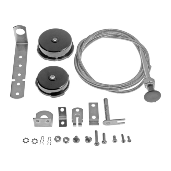
CHOKE
CONVERSION KIT
55101
BEFORE YOU BEGIN:
• Always wear proper safety
equipment when performing repairs.
• Ensure at your point of purchase
that this part fits your exact
vehicle configuration.
• Reference the appropriate service
manual for your vehicle. If you do
not have a service manual, and do
not have the training or experience
to perform the necessary
procedures correctly, seek the
services of a qualified technician.
NEED HELP?
Please call our Technical Support
team for assistance from our team of
certified automotive experts.
1-866-933-2911
© 2023 No reproduction in whole or in part without prior written approval.
55101_Instructions
Remove air filter from carburetor and determine the
type of automatic choke on the car. There are two
basic types:
Integrated
choke
If automatic choke thermostat is an integral part
of carburetor body and uses a black cap or plastic
or metal disc, it is an integrated choke. Follow the
first set of instructions for integrated choke.
Non-integrated
choke
If a rod connects the carburetor choke shaft to
the thermostat mechanism which is located in
the intake manifold, it is a non-integrated choke.
Follow the second set of instructions
for non-integrated choke.
INTEGRATED CHOKE
INSTALLATION
INSTRUCTIONS
STEP 1:
Remove the black plastic cap or metal disc. If a
heat tube is attached to the choke cap, remove
and discard it. Do not remove if it is attached to
the carburetor body. Save all screws, retainers,
clamps, etc., for use in installing this kit. Make
sure the choke shaft and choke butterfly operate
smoothly. If not, clean with choke cleaner.
Dorman Products, Inc. Corporate Office and Customer Service: 1-800-523-2492.
Disclaimer: It is impossible in these instructions to account for all possible circumstances or situations that you may experience when
attempting to install this product. Please consult with a qualified auto technician before attempting to perform any work you are not qualified to
do. Automobiles can be hazardous to work on; be sure to take all necessary safety precautions. Failure to do so may result in property damage
or personal injury. Certain motor vehicle standards and performance requirements may apply to your motor vehicle (such as Federal Motor
Vehicle Safety Standards by the National Highway Traffic Safety Administration). Be sure that your work is performed in accordance with such
standards and that you do not disable any motor vehicle safety feature.
STEP 2:
Determine which of the two plastic caps included
in this kit best fits your carburetor. Discard the
one you will not need. On some carburetors, the
flanges of the cap fit between the three set pins.
On others, the flanges will fit securely within the
carburetor body.
STEP 3:
Breakaway line
Activator lever
Activator shaft
R-clips
Activator shaft
Choke butterfly
Crimp tight
with pliers (do
not remove)
Choke
tang
Insert the actuator shaft in the new plastic cap,
with the activator lever inside the cap. If you are
using the larger cap, insert the activator shaft
assembly (first illustration) in the cap as shown
in the second illustration and set depth. If you
are using the smaller cap, the activator lever will
have to be shortened at the break-away points
as shown in the first illustration. This is done by
grasping activator lever with pliers above break-
away line and then bending back and forth until
the excess portion breaks away. Do one side at a
time. Set the depth of the activator lever within
the cap so it will catch the choke tang in the
carburetor (third illustration), but not so deep
that the activator will bind on the choke housing.
Once the exact position has been determined,
remove the shaft and install the inside R-clip.
Then place the shaft in position again and install
outer R-clip (second illustration).
PAGE 1 OF 9
Activator
lever
Advertisement
Table of Contents

Subscribe to Our Youtube Channel
Related Manuals for Dorman 55101


Summary of Contents for Dorman 55101
- Page 1 1-866-933-2911 Dorman Products, Inc. Corporate Office and Customer Service: 1-800-523-2492. Disclaimer: It is impossible in these instructions to account for all possible circumstances or situations that you may experience when attempting to install this product. Please consult with a qualified auto technician before attempting to perform any work you are not qualified to do.
- Page 2 55101: CHOKE CONVERSION KIT PAGE 2 OF 9 STEP 4: STEP 7: STEP 11: Insert the choke cable wire inside the cable and Cable clamp Mount on activator Manifold through the hole in the collar fitting referred to in shaft outside cap L-bracket Step 4.
- Page 3 55101: CHOKE CONVERSION KIT PAGE 3 OF 9 NON-INTEGRATED OPERATING STEP 5: CHOKE INSTALLATION INSTRUCTIONS Determine the direction in which your chokes INSTRUCTIONS operates, so that when installation is completed, Follow these operating instructions to obtain the choke butterfly will close when you pull out...
-
Page 4: Antes De Comenzar
(segunda ilustración). 1-866-933-2911 Dorman Products, Inc. Oficina Corporativa y Servicio a Clientes: +1-800-523-2492 Descargo de responsabilidad: A pesar de que se haga todo lo posible para garantizar que esta información sea completa y exacta, es imposible tener en cuenta todas las posibles circunstancias o situaciones. Por favor, consulte a un técnico calificado de automóviles antes de intentar realizar cualquier trabajo si no está... - Page 5 55101: KIT DE CONVERSIÓN DEL DIFUSOR PÁGINA 5 DE 9 PASO 4: PASO 7: PASO 11: Inserte el cable del difusor dentro del cable y a Montaje en la tapa Soporte Abrazadera de cable través del orificio en el collar mencionado en el...
-
Page 6: Instrucciones De Funcionamiento
55101: KIT DE CONVERSIÓN DEL DIFUSOR PÁGINA 6 DE 9 INSTRUCCIONES DE INSTRUCCIONES DE PASO 5: INSTALACIÓN DEL FUNCIONAMIENTO Determine la dirección en la que funcionan los DIFUSOR NO INTEGRADO difusores, de manera que, cuando se complete la Siga estas instrucciones de funcionamiento instalación, el difusor se cierre cuando extraiga... - Page 7 (deuxième illustration). 1-866-933-2911 Dorman Products, Inc. Siège social et service à la clientèle : 1-800-523-2492 Clause de non-responsabilité: Malgré tous les efforts effectués pour s’assurer que l’information soit complète et exacte, il est impossible de prendre en compte toutes les situations et circonstances possibles. Veuillez consulter un technicien qualifié avant d’effectuer des travaux que vous n’êtes pas qualifié...
- Page 8 55101 : TROUSSE DE CONVERSION DE L’ÉTRANGLEUR PAGE 8 DE 9 ÉTAPE 4 : ÉTAPE 7 : ÉTAPE 11 : Insérer le fil du câble d’étrangleur à l’intérieur Montage sur l’arbre de Support Collier de serrage du câble et à travers le trou du raccord de collier l’activateur à...
-
Page 9: Instructions D'utilisation
55101 : TROUSSE DE CONVERSION DE L’ÉTRANGLEUR PAGE 9 DE 9 INSTRUCTIONS INSTRUCTIONS ÉTAPE 5 : D’INSTALLATION D’UTILISATION Déterminer le sens de fonctionnement de votre DE L’ÉTRANGLEUR étrangleur, de sorte qu’une fois l’installation Suivre ces instructions d’utilisation pour obtenir terminée, le papillon de l’étrangleur se ferme NON INTÉGRÉ...
Need help?
Do you have a question about the 55101 and is the answer not in the manual?
Questions and answers