Rack server - amd epyc 9004, 1u up 4-bay gen4 nvme/sata/sas (aab1/platinum redundant power supplies), 1u up 4-bay sata/sas (aab2/platinum redundant power supplies), 1u up 4-bay gen4 nvme/sata/sas (aag1/titanium redundant power supplies), 1u up 4-bay sata/ (163 pages)
Rack server - 5th/4th gen intel xeon scalable - 1u dp 4 x pcie gen5 gpus immersion (98 pages)
Summary of Contents for Gigabyte R113-C10-AA01
Page 1
R113-C10-AA01 R113-C10-AA02 
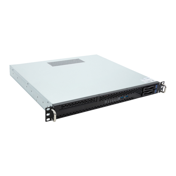
Rack Server - AMD Ryzen™ 7000 - 1U UP 4-Bay SATA Single 350W Bronze power supply (AA01) Single 400W Gold power supply (AA02) User Manual Rev. 1.0...
Page 2
GIGABYTE's prior written permission. Documentation Classifications In order to assist in the use of this product, GIGABYTE provides the following types of documentation: User Manual: detailed information & steps about the installation, configuration and use of this product (e.g.
Page 3
Conventions The following conventions are used in this user's guide: NOTE! Pieces of additional information related to the current topic. CAUTION! Precautionary measures to avoid possible hardware or software problems. WARNING! Alerts to any damage that might result from doing or not doing specific actions.
Page 4
Server Warnings and Cautions Before installing a server, be sure that you understand the following warnings and cautions. WARNING! To reduce the risk of electric shock or damage to the equipment: • Do not disable the power cord grounding plug. The grounding plug is an important safety feature.
Page 5
Electrostatic Discharge (ESD) CAUTION! ESD CAN DAMAGE DRIVES, BOARDS, AND OTHER PARTS. WE RECOMMEND THAT YOU PERFORM ALL PROCEDURES AT AN ESD WORKSTATION. IF ONE IS NOT AVAILABLE, PROVIDE SOME ESD PROTECTION BY WEARING AN ANTI-STATIC WRIST STRAP AT- TACHED TO CHASSIS GROUND -- ANY UNPAINTED METAL SURFACE -- ON YOUR SERVER WHEN HANDLING PARTS.
Page 6
Installing or removing jumpers: A jumper is a small plastic encased conductor that slips over two jumper pins. Some jumpers have a small tab on top that can be gripped with fin-gertips or with a pair of fine needle nosed pliers. If the jumpers do not have such a tab, take care when us- ing needle nosed pliers to remove or install a jumper;...
Table of Contents Chapter 1 Hardware Installation ...................10 Installation Precautions .................. 10 Product Specifications ..................11 System Block Diagram ................... 15 Chapter 2 System Appearance ..................16 Front View ...................... 16 Rear View ....................... 17 Front Panel LED and Buttons ................ 18 Rear System LAN LEDs .................
Chapter 1 Hardware Installation Installation Precautions The motherboard/system contain numerous delicate electronic circuits and components which can become damaged as a result of electrostatic discharge (ESD). Prior to installation, carefully read the service guide and follow these procedures: • Prior to installation, do not remove or break motherboard S/N (Serial Number) sticker or warranty sticker provided by your dealer.
Product Specifications NOTE: We reserve the right to make any changes to the product specifications and product-related information without prior notice. System Security Server Socket Operating Properties 1U Dimension 430 (W) x 43.5 (H) x 393.2(D) mm System fan Power Supply ...
Page 12
Expansion Slot Riser Card CRS101R: 1 x PCIe x16 (Gen5 x16) FHHL slot, from CPU 1 x M.2 slot: M-key PCIe Gen5 x4, from CPU Supports 2242/2280 cards Internal I/O 1 x M.2 slot 1 x TPM header Front I/O ...
Page 13
Security Server Operating Properties System fan Power Supply Power Supply R113-C10-AA01 Single 350W 80 Plus Bronze power supply AC Input: 100-240V~/ 6-3A, 50-60Hz DC Output: Max 350W/ 100-240V~ + 12V/ 29A + 5V/ 14A ...
Page 14
System Aspeed® AST2600 management controller Management GIGABYTE Management Console (AMI MegaRAC SP-X) web interface Dashboard HTML5 KVM Sensor Monitor (Voltage, RPM, Temperature, CPU Status …etc.) Sensor Reading History Data FRU Information SEL Log in Linear Storage / Circular Storage Policy ...
Chapter 2 System Appearance Front View HDD0 HDD1 Description Front Panel LEDs and Buttons USB 3.2 Gen1 Port x 2 3.5" Drive Bays • Refer to section 2-3 Front Panel LEDs and Buttons for a detailed description of the function of the LEDs.
Rear View 4 5 6 7 SLOT1 Description VGA Port Serial Port USB 3.2 Gen1 Port x 2 Server Management LAN Port 1 GbE LAN Port #1 1 GbE LAN Port #2 ID Button with LED PCIe Card Slot System Appearance - 17 -...
Front Panel LED and Buttons Reset No. Name Color Status Description Power button Press the button to power on the system. with LED Green System is powered on Green Blink System is in ACPI S1 state (sleep mode) Power LED •...
Rear System LAN LEDs Name Color Status Description Yellow 1 Gbps data rate 1GbE Speed Green 100 Mbps data rate 10 Mbps data rate Link between system and network or no access Green 1GbE Link / Blink Data transmission or reception is occurring. Activity LED No data transmission or reception is occurring.
Hard Disk Drive LEDs HDD Present RAID SKU LED #1 Locate Rebuilding HDD Access Fault (No Access) Green ON(*1) BLINK (*2) Disk LED (LED on Back Panel) Amber No RAID configuration Removed HDD Green ON(*1) (via HBA) Slot (LED on Amber Back Panel) Green...
Chapter 3 System Hardware Installation Pre-installation Instructions Computer components and electronic circuit boards can be damaged by discharges of static electricity. Working on computers that are still connected to a power supply can be extremely dangerous. Follow the simple guidelines below to avoid damage to your computer or injury to yourself.
Removing and Installing the Chassis Cover Before you remove or install the system cover • Make sure the system is not turned on or connected to AC power. Follow these instructions to remove the chassis cover: Remove the two screws securing the top cover. Slide the cover to the rear of the system and then remove the cover in the direction indicated by the arrow.
Removing and Installing the Hard Disk Drive Read the following guidelines before you begin to install the hard disk drive: • Take note of the HDD tray orientation before sliding it out. • The tray will not fit back into the bay if it is inserted incorrectly. •...
Page 24
Follow these instructions to install one Hard disk drive: Loosen and remove the screws securing the HDD cage. Slide the HDD into the HDD cage. Replace the HDD cage to system and secure it with screw. Connect necessary cables. System Hardware Installation - 24 -...
Removing and Installing the CPU and Heat Sink Read the following guidelines before you begin to install the CPU: • Make sure that the motherboard supports the CPU. • Always turn off the computer and unplug the power cord from the power outlet before installing the CPU to prevent hardware damage.
Page 26
• Lock the CPU by using a Torx T20 screwdriver to tighten screw. • When installing the heatsink to CPU, use a Torx T20 screwdriver to tighten 4 captive nuts in sequence as 1-4. • The screw tightening torque: 13.5 ± 0.5 kgf-cm. •...
Removing and Installing Memory Read the following guidelines before you begin to install the memory: • Make sure that the motherboard supports the memory. It is recommended that memory of the same capacity, brand, speed, and chips be used. • Always turn off the computer and unplug the power cord from the power outlet before installing the memory to prevent hardware damage.
3-4-2 Removing and Installing a Memory Module Before installing a memory module, make sure to turn off the computer and unplug the power cord from the power outlet to prevent damage to the memory module. Be sure to install DDR5 DIMMs on to this motherboard.
Removing and Installing the PCIe Card • Voltages can be present within the server whenever an AC power source is connected. This voltage is present even when the main power switch is in the off position. Ensure that the system is powered off and all power sources have been disconnected from the server prior to installing a PCIe card.
Installing the M.2 Device CAUTION The position of the stand-off screw will depend on the size of the M.2 device. The stand-off screw is pre-installed for 2280 cards as standard. Refer to the size of the M.2 device and change the position of the stand-off screw accordingly.
Cable Routing Motherboard: FP_1 Front Panel LEDs and Buttons Cable Front IO Board: J2 Motherboard: F_U32 Front USB Cable Front IO Board: J1 Motherboard: ATX System Power Cable Power Supply Cable System Hardware Installation - 31 -...
Page 32
Motherboard: SATA1 Front HDD Backplane Board: SATA1 SATA Cable Motherboard: SATA3 Front HDD Backplane Board: SATA2 System Hardware Installation - 32 -...
Page 33
Motherboard: ATX12V_2X4 HDD Backplane Power Cable Front HDD Backplane Board: -- System Hardware Installation - 33 -...
Chapter 5 BIOS Setup BIOS (Basic Input and Output System) records hardware parameters of the system in the EFI on the motherboard. Its major functions include conducting the Power-On Self-Test (POST) during system startup, saving system parameters, loading the operating system etc. The BIOS includes a BIOS Setup program that allows the user to modify basic system configuration settings or to activate certain system features.
Page 37
Main This setup page includes all the items of the standard compatible BIOS. Advanced This setup page includes all the items of AMI BIOS special enhanced features. (ex: Auto detect fan and temperature status, automatically configure hard disk parameters.) ...
The Main Menu Once you enter the BIOS Setup program, the Main Menu (as shown below) appears on the screen. Use arrow keys to move among the items and press <Enter> to accept or enter other sub-menu. Main Menu Help The on-screen description of a highlighted setup option is displayed on the bottom line of the Main Menu.
Page 39
Parameter Description Access Level Displays the privileges level information. Project Name Displays the project name information. Project Version Displays version number of the BIOS setup utility. Build Date and Time Displays the date and time when the BIOS setup utility was created. BMC Information (Note1) BMC Firmware Version...
Advanced Menu The Advanced Menu displays submenu options for configuring the function of various hardware components. Select a submenu item, then press <Enter> to access the related submenu screen. MC13-LE0 BIOS Setup - 40 -...
5-2-1 Trusted Computing Parameter Description TPM20 Device Found Firmware Version Displays the firmware version information. Vendor Displays the vendor information. Enable/Disable BIOS support for security device. OS will not show security device. TCG EFI protocol and INT1A interface will not be Security Device Support available.
5-2-3 AST2600 Super IO Configuration Description Parameter AST2600 Super IO Configuration Super IO Chip Displays the super IO chip information Serial Port 1 Press [Enter] for configuration of advanced items. Configuration BIOS Setup - 45 -...
Page 46
5-2-3-1 Serial Port 1 Configuration Description Parameter Serial Port 1 Configuration Enable/Disable the Serial Port (COM). When set to Enabled allows you to configure the Serial port 1 settings. When set to Disabled, displays no Serial Port (Note) configuration for the serial port. Options available: Disabled, Enabled.
5-2-4 S5 RTC Wake Settings Parameter Description Enable/Disable system wake on alarm event. Options available: Disabled, Fixed Time. When Fixed Time is selected, Wake System from S5 system will wake on the hr::min::sec specified. Default setting is Disabled. BIOS Setup - 47 -...
5-2-5 Serial Port Console Redirection Parameter Description Select whether to enable console redirection for specified device. Console COM Console redirection enables the users to manage the system from a remote Redirection (Note) location. Options available: Disabled, Enabled. Default setting is Disabled. Press [Enter] to configure advanced items.
Page 49
Parameter Description Parity – A parity bit can be sent with the data bits to detect some transmission errors. – Even: parity bit is 0 if the num of 1's in the data bits is even. – Odd: parity bit is 0 if num of 1's in the data bits is odd. –...
Page 50
Parameter Description Legacy Console Redirection Press [Enter] to configure advanced items. Redirection COM Port – Selects a COM port for Legacy serial redirection. – Default setting is COM1. Resolution – Selects the number of rows and columns used in Console Redirection for legacy OS support.
Page 51
Parameter Description Flow Control EMS – Flow control can prevent data loss from buffer overflow. When sending data, if the receiving buffers are full, a 'stop' signal can Serial Port for Out-of-Band be sent to stop the data flow. Once the buffers are empty, a 'start' EMS Console Redirection signal can be sent to re-start the flow.
5-2-6 CPU Configuration Description Parameter CPU Configuration Displays the module version information. Module Version Enable/Disable the generation of ACPI_PPC, _PSS, and _PCT objects. PSS Support Options available: Disabled, Enabled. Default setting is Enabled. Options available: PState 0, PState 1, PState 2, PState 3. PPC Adjustment Default setting is PState 0.
5-2-7 PCI Subsystem Settings Description Parameter PCI BUS Driver Version Displays PCI BUS driver version information. When enabled, this setting will initialize the device expansion ROM for PCIE_1 I/O ROM the related PCI-E slot. Options available: Disabled, Enabled. Default setting is Enabled. Enable/Disable LE0_M2 device and initialize the device expansion ROM.
Page 54
Description Parameter Enable/Disable memory mapped I/O to 4GB or greater address space (Above 4G Decoding). Above 4G Decoding Options available: Disabled, Enabled. Default setting is Enabled. Options available: Disabled, Enabled. Default setting is Enabled. Re-Size BAR Support If the system has SR-IOV capable PCIe devices, this item Enable/Disable Single Root IO Virtualization Support.
5-2-8 USB Configuration Parameter Description USB Configuration USB Module Version Displays the USB module version information. USB Controllers Displays the supported USB controllers. USB Devices: Displays the USB devices connected to the system. Enable/Disable the Legacy USB support function. AUTO option disables legacy support if no USB devices are connected.
Page 56
Parameter Description Enables the I/O port 60h/64h emulation support. This should be enabled for the complete USB Keyboard Legacy support for non- Port 60/64 Emulation USB aware OS. Options available: Disabled, Enabled. Default setting is Enabled. USB hardware delays and time-outs Selects the time-out value for USB Control/Bulk/Interrupt transfers.
5-2-13 SATA Configuration Parameter Description Displays the installed HDD devices information. System will automatically SATA Configuration detect HDD type. BIOS Setup - 61 -...
5-2-14 Chipset Configuration Parameter Description This option provides user to set the mode of operation if an AC / power loss occurs. Restore AC Power Loss Options available: Power Off, Power On, Last State, Unspecified. Default setting is Last State. BIOS Setup - 62 -...
5-2-15 RAM Disk Configuration Parameter Description Specifies the type of memory to use from available memory pool in system to create a disk. Disk Memory Type Options available: Boot Service Data, Reserved. Default setting is Boot Service Data. Creates a raw RAM disk. Size (Hex) ...
5-2-16 Tls Auth Configuration Parameter Description Press [Enter] for configuration of advanced items. Enroll Cert – Press [Enter] to enroll a certificate • Enroll Cert Using File • Cert GUID Server CA Configuration Input digit character in 1111111-2222-3333-4444-1234567890ab format. –...
Page 67
Parameter Description Link Speed – Allows for automatic link speed adjustment. – Options available: Auto Negotiated, 10 Mbps Half, 10 Mbps Full, 100 Mbps Half, 100 Mbps Full. Default setting is Auto Negotiated. Wake On LAN NIC Configuration –...
Page 69
Description Parameter Press [Enter] to configure advanced items. Link Speed – Default setting is Auto Negotiated. Wake On LAN – Enables power on of the system via LAN. Note that configuring Wake on LAN in the operating system does not change the value of NIC Configuration this setting, but does override the behavior of Wake on LAN in OS controlled power states.
5-2-20 VLAN Configuration Parameter Description Press [Enter] to configure advanced items. Create new VLAN VLAN ID – Sets VLAN ID for a new VLAN or an existing VLAN. – Press the <+> / <-> keys to increase or decrease the desired values. –...
5-2-21 MAC IPv4 Network Configuration Parameter Description Indicates whether network address is configured successfully or not. Configured Options available: Enabled, Disabled. Default setting is Disabled. Options available: Enabled, Disabled. Default setting is Enabled. Enable DHCP (Note) Local IP Address Press [Enter] to configure local IP address. (Note) Press [Enter] to configure local NetMask.
5-2-22 MAC IPv6 Network Configuration Parameter Description Press [Enter] to configure advanced items. Displays the MAC Address information. Interface ID – The 64 bit alternative interface ID for the device. The string is colon separated. e.g. ff:dd:88:66:cc:1:2:3. DAD Transmit Count ...
Chipset Setup Menu Chipset Setup menu displays submenu options for configuring the function of the North Bridge. Select a submenu item, then press <Enter> to access the related submenu screen. Parameter Description North Bridge Press [Enter] for configuration of advanced items. BIOS Setup - 74 -...
5-4-1 System Event Log Parameter Description Enabling / Disabling Options Change this item to enable or disable all features of System Event SEL Components Logging during boot. Options available: Disabled, Enabled. Default setting is Enabled. Erasing Settings Choose options for erasing SEL. Erase SEL Options available: No/Yes, On next reset/Yes, On every reset.
5-4-2 View FRU Information The FRU page is a simple display page for basic system ID information, as well as System product information. Items on this window are non-configurable. (Note) The model name will vary depends on the product you purchased BIOS Setup - 79 -...
5-4-3 Bmc self test log Parameter Description Log area usage = 00 out of 20 logs Choose options for erasing SEL. Erase Log Options available: Yes, On every reset/ No. Default setting is Yes, On every reset. Choose options for reactions to a full SEL. When log is Full Options available: Clear Log, Do not log any more.
5-4-4 BMC VLAN Configuration Parameter Description BMC VLAN Configuration Sets VLAN ID for a new VLAN or an existing VLAN. BMC VLAN ID Press the <+> / <-> keys to increase or decrease the desired values. The valid range is from 0 to 4094. Sets 802.1Q Priority for a new VLAN or an existing VLAN.
5-4-5 BMC Network Configuration Parameter Description BMC network configuration Lan Channel 1 Selects to configure LAN channel parameters statically or dynamically (DHCP). Do nothing option will not modify any BMC network parameters Configuration Address source during BIOS phase. Options available: Unspecified, Static, DynamicBmcDhcp. Default setting is DynamicBmcDhcp.
5-4-6 BMC User Settings Parameter Description BMC User Settings Add User Press [Enter] to add a user. Delete User Press [Enter] to delete a user. Change User Settings Press [Enter] to change the settings. BIOS Setup - 83 -...
5-4-7 IPv6 BMC Network Configuration Parameter Description IPv6 BMC network configuration IPv6 BMC Lan Channel 1 Enable/Disable IPv6 BMC LAN channel function. When this item is disabled, the system will not modify any BMC network during BIOS IPv6 BMC Lan Option phase.
Security Menu The Security menu allows you to safeguard and protect the system from unauthorized use by setting up access passwords. There are two types of passwords that you can set: • Administrator Password Entering this password will allow the user to access and change all settings in the Setup Utility. •...
5-5-1 Secure Boot The Secure Boot submenu is applicable when your device is installed the Windows 8 (or above) operating ® system. Parameter Description System Mode Displays if the system is in User mode or Setup mode. Enable/ Disable the Secure Boot function. Secure Boot Options available: Enabled, Disabled.
Page 87
Parameter Description Press [Enter] to configure advanced items. Please note that this item is configurable when Secure Boot Mode is set to Custom. Factory Key Provision – Allows to provision factory default Secure Boot keys when system is in Setup Mode.
Boot Menu The Boot menu allows you to set the drive priority during system boot-up. BIOS setup will display an error message if the legacy drive(s) specified is not bootable. Parameter Description Boot Configuration Number of seconds to wait for setup activation key. 65535 (0xFFFF) Setup Prompt Timeout means indefinite waiting.
Save & Exit Menu The Save & Exit menu displays the various options to quit from the BIOS setup. Highlight any of the exit options then press <Enter>. Parameter Description Save Options Saves changes made and closes the BIOS setup. Save Changes and Exit Options available: Yes, No.
Page 90
Parameter Description Loads the default settings for all BIOS setup parameters. Setup Defaults are quite demanding in terms of resources consumption. If you are using low-speed memory chips or other kinds of low-performance components Restore Defaults and you choose to load these settings, the system might not function properly.
BIOS Recovery The system has an embedded recovery technique. In the event that the BIOS becomes corrupt the boot block can be used to restore the BIOS to a working state. To restore your BIOS, please follow the instructions listed below: Recovery Instruction: 1.
BIOS POST Beep code (AMI standard) 5-9-1 PEI Beep Codes # of Beeps Description Memory not Installed. Memory was installed twice (InstallPeiMemory routine in PEI Core called twice) Recovery started DXEIPL was not found DXE Core Firmware Volume was not found Recovery failed S3 Resume failed Reset PPI is not available...