Table of Contents
Advertisement
Quick Links
Advertisement
Table of Contents

Related Manuals for Gigabyte R161-R13


Summary of Contents for Gigabyte R161-R13
- Page 1 R161-R13 1U Intel® X299 Server System Service Guide Rev. 1.0...
- Page 2 GIGABYTE's prior written permission. Documentation Classifications In order to assist in the use of this product, GIGABYTE provides the following types of documentations: For detailed product information, carefully read the User's Manual.
- Page 3 Conventions The following conventions are used in this user's guide: NOTE! Gives bits and pieces of additional information related to the current topic. CAUTION! Gives precautionary measures to avoid possible hardware or software problems. WARNING! Alerts you to any damage that might result from doing or not doing specific actions.
- Page 4 Server Warnings and Cautions Before installing a server, be sure that you understand the following warnings and cautions. WARNING! To reduce the risk of electric shock or damage to the equipment: • Do not disable the power cord grounding plug. The grounding plug is an important safety feature.
- Page 5 Electrostatic Discharge (ESD) CAUTION! ESD CAN DAMAGE DRIVES, BOARDS, AND OTHER PARTS. WE RECOMMEND THAT YOU PERFORM ALL PROCEDURES AT AN ESD WORKSTATION. IF ONE IS NOT AVAILABLE, PROVIDE SOME ESD PROTECTION BY WEARING AN ANTI-STATIC WRIST STRAP AT- TACHED TO CHASSIS GROUND -- ANY UNPAINTED METAL SURFACE -- ON YOUR SERVER WHEN HANDLING PARTS.
- Page 6 CAUTION! Risk of explosion if battery is replaced incorrectly or with an incorrect type. Replace the battery only with the same or equivalent type recommended by the manufacturer. Dispose of used bat- teries according to the manufacturer’s instructions.
-
Page 7: Table Of Contents
Table of Contents Chapter 1 Hardware Installation ...................10 Installation Precautions .................. 10 Product Specifications ..................11 System Block Diagram ................... 14 Chapter 2 System Appearance ..................15 Front View ...................... 15 Rear View ....................... 15 Front Panel LED and Buttons ................ 16 Rear System LAN LEDs ................. - Page 8 This page intentionally left blank - 8 -...
- Page 9 This page intentionally left blank - 9 -...
-
Page 10: Chapter 1 Hardware Installation
Chapter 1 Hardware Installation Installation Precautions The motherboard/system contain numerous delicate electronic circuits and components which can become damaged as a result of electrostatic discharge (ESD). Prior to installation, carefully read the service guide and follow these procedures: • Prior to installation, do not remove or break motherboard S/N (Serial Number) sticker or warranty sticker provided by your dealer. -
Page 11: Product Specifications
Product Specifications Intel® Core™ X series 44-lane/28-lane processors Š Socket Socket 1 x LGA 2066 Š Mounting pitch: square ILM (80x80mm) Š Chipset Intel® X299 Express Chipset Š Socket Memory 8 x DIMM slots Š DDR4 memory modules supported only Š... - Page 12 Internal 3 x Power supply connectors Š Connectors 5 x SlimSAS connectors Š 2 x fan headers Š 1 x USB 3.0 header Š Socket 1 x TPM header Š 1 x VROC connector Š 1 x Front panel header Š...
- Page 13 System Aspeed® AST2500 management controller Š Management Avocent® MergePoint IPMI 2.0 web interface: Š Network settings Š Network security settings Š ocket Hardware information Š Users control Š Services settings Š IPMI settings Š Sessions control Š LDAP settings Š Power control Š...
-
Page 14: System Block Diagram
System Block Diagram - 14 - Hardware Installation... -
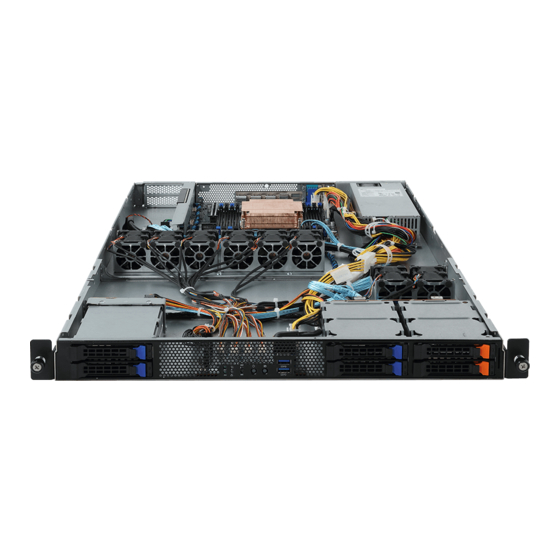
Page 15: Chapter 2 System Appearance
Chapter 2 System Appearance Front View HDD #4 HDD #0 HDD #2 NVMe Compa bile HDD #5 HDD #1 HDD #3 NVMe Compa bile Description Front Panel LEDs and Buttons USB 3.0 Port x 2 Orange HDD Latches Support NVMe •... -
Page 16: Front Panel Led And Buttons
Front Panel LED and Buttons Name Color Status Description ID Button Press the button to activate system identification Green System is powered on Green Blink System is in ACPI S1 state (sleep mode) Power button • System is not powered on or in ACPI S5 state with LED (power off) •... -
Page 17: Rear System Lan Leds
Rear System LAN LEDs Name Color Status Description Yellow 1 Gbps data rate 1GbE Green 100 Mbps data rate Speed LED 10 Mbps data rate Link between system and 1GbE Green network or no access Link/ Blink Data transmission or receiving is occurring Activity No data transmission or receiving is occurring... -
Page 18: Hard Disk Drive Leds
Hard Disk Drive LEDs HDD Present RAID SKU LED1 Locate Rebuilding Fault Access (No Access) Disk LED Green Green ON(*1) (LED on Back Panel) Amber Amber No RAID configuration Green ON(*1) Green (via HBA, ICH) Removed HDD Slot (LED on Back Panel) Amber Amber Green... -
Page 19: Chapter 3 System Hardware Installation
Chapter 3 System Hardware Installation Pre-installation Instructions Computer components and electronic circuit boards can be damaged by discharges of static electricity. Working on computers that are still connected to a power supply can be extremely dangerous. Follow the simple guidelines below to avoid damage to your computer or injury to yourself. -
Page 20: Removing Chassis Cover
Removing Chassis Cover Before you remove or install the system cover • Make sure the system is not turned on or connected to AC power. Follow these instructions to remove the system cover: Loosen and the two thumbscrew at the rear of the system. Remove the single secrew at the front of the system. -
Page 21: Installing The Cpu
Installing the CPU Read the following guidelines before you begin to install the CPU: • Make sure that the motherboard supports the CPU. • Always turn off the computer and unplug the power cord from the power outlet before installing the CPU to prevent hardware damage. -
Page 22: Installing The Heat Sink
Installing the Heat Sink Follow these instructions to install the heat sinks: Apply thermal compound evenly on the top of the CPU. Remove the protective cover from the underside of the heat sink. Place the heat sink(s) on top of the CPU and tighten the four positioning screws. System Hardware Installation - 22 -... -
Page 23: Installing The Memory
Installing the Memory Read the following guidelines before you begin to install the memory: • Make sure that the motherboard supports the memory. It is recommended that memory of the same capacity, brand, speed, and chips be used. • Always turn off the computer and unplug the power cord from the power outlet before installing the memory to prevent hardware damage. -
Page 24: Installing A Memory
3-4-2 Installing a Memory Before installing a memory module, make sure to turn off the computer and unplug the power cord from the power outlet to prevent damage to the memory module. Be sure to install DDR4 DIMMs on this motherboard. Follow these instructions to install the Memory: Insert the DIMM memory module vertically into the DIMM slot, and push it down. -
Page 25: Installing The Pci Expansion Card
Installing the PCI Expansion Card • Voltages can be present within the server whenever an AC power source is connected. This voltage is present even when the main power switch is in the off position. Ensure that the system is powered-down and all power sources have been disconnected from the server prior to installing a PCI card. -
Page 26: Installing The Hard Disk Drive
Installing the Hard Disk Drive Read the following guidelines before you begin to install the Hard disk drive: • Take note of the drive tray orientation before sliding it out. • The tray will not fit back into the bay if inserted incorrectly. •... -
Page 27: Replacing The Fan Assemblly
Replacing the FAN Assemblly Follow these instructions to replace the fan assembly: Lift up the fan assembly from the chassis. Reverse the previous steps to install the replacement fan assembly. - 27 - System Hardware Installation... -
Page 28: Replacing The Power Supply
Replacing the Power Supply Follow these instructions to replace the power supply: Remove the screws securing power supply. Slide the power supply inward to remove the power supply from the system. Insert the replacement power supply firmly into the chassis. Connect the AC power cord to the replacement power supply. -
Page 29: Cable Routing
Cable Routing System Power Cable Front IO Board Power Cable OLD_REV OLD_REV OLD_REV OLD_REV OLD_REV OLD_REV OLD_REV OLD_REV Front Panel USB 3.0 Cable Front IO Board Power Cable OLD_REV OLD_REV OLD_REV OLD_REV OLD_REV OLD_REV OLD_REV OLD_REV - 29 - System Hardware Installation... - Page 30 HDD Back Plane Board Power Cable HDD Back Plane Board Signal Cable OLD_REV OLD_REV OLD_REV OLD_REV OLD_REV OLD_REV OLD_REV OLD_REV On-Board SATA to HDD Back Plane Board NVMe Cable Cable OLD_REV OLD_REV OLD_REV OLD_REV OLD_REV OLD_REV OLD_REV OLD_REV System Hardware Installation - 30 -...
- Page 31 System Fan Cable OLD_REV OLD_REV OLD_REV OLD_REV OLD_REV OLD_REV OLD_REV OLD_REV OLD_REV OLD_REV OLD_REV OLD_REV OLD_REV OLD_REV OLD_REV OLD_REV CAUTION! To connect system fan connector, follow the instruction: • Black/Red cable connect to odd numbered connector. • White/Amber cable connect to even numbered connector. - 31 - System Hardware Installation...
- Page 32 SMBus Cable PMBus Cable OLD_REV OLD_REV OLD_REV OLD_REV OLD_REV OLD_REV OLD_REV OLD_REV System Hardware Installation - 32 -...
-
Page 33: Chapter 4 Motherboard Components
Chapter 4 Motherboard Components Motherboard Components 14 15 16 17 Item Description 2 x 4 Pin CPU Power Connector Auxiliary Power Connector for Overclocking 2 x 12 Pin System Power Connector Front Panel Header VROC Upgrade Module CPU Fan Connector (for Liquid Cooling Pump) SlimLine 4i Connector (PCIe Signal) SlimLine 4i Connector (PCIe Signal) SlimLine 4i Connector (PCIe Signal) - Page 34 USB 3.0 Connector TPM Connector System Battery Cable Connector PMBus Connector M.2 slot (PCIe Gen3 x4, Support NGFF-2280, M-Key) IPMB Connector Proprietary Riser Slot 2 x 15 Pin HDD Back Plane Board Connector PCIe x16 Slot Motherboard Components - 34 -...
-
Page 35: Jumper Setting
Jumper Setting Default Recovery Enable ME_RCVR ME Force Enable Update Default ME_UPDATE BIOS Default Recovery Password Enable Enable BIOS_RCVR Clear Default BIOS_PWD Enable Clear CMOS CLR_CMOS Default - 35 - Motherboard Components...
Need help?
Do you have a question about the R161-R13 and is the answer not in the manual?
Questions and answers