Table of Contents
Advertisement
Quick Links
Copyright
This publication, including all photographs, illustrations and software, is protected under
international copyright laws, with all rights reserved. Neither this manual, nor any of the
material contained herein, may be reproduced without written consent of the author.
Version 1.0
Disclaimer
The information in this document is subject to change without notice. The manufacturer
makes no representations or warranties with respect to the contents hereof and specifically
disclaims any implied warranties of merchantability or fitness for any particular purpose.
The manufacturer reserves the right to revise this publication and to make changes from
time to time in the content hereof without obligation of the manufacturer to notify any
person of such revision or changes.
Trademark Recognition
Microsoft, MS-DOS and Windows are registered trademarks of Microsoft Corp.
AMD, Athlon, Sempron, and Duron are registered trademarks of AMD Corporation.
Other product names used in this manual are the properties of their respective owners and
are acknowledged.
Federal Communications Commission (FCC)
This equipment has been tested and found to comply with the limits for a Class B digital
device, pursuant to Part 15 of the FCC Rules. These limits are designed to provide reason-
able protection against harmful interference in a residential installation. This equipment
generates, uses, and can radiate radio frequency energy and, if not installed and used in
accordance with the instructions, may cause harmful interference to radio communications.
However, there is no guarantee that interference will not occur in a particular installation.
If this equipment does cause harmful interference to radio or television reception, which
can be determined by turning the equipment off and on, the user is encouraged to try to
correct the interference by one or more of the following measures:
•
Reorient or relocate the receiving antenna.
•
Increase the separation between the equipment and the receiver.
•
Connect the equipment onto an outlet on a circuit different from that to which
the receiver is connected.
•
Consult the dealer or an experienced radio/TV technician for help.
Shielded interconnect cables and a shielded AC power cable must be employed with this
equipment to ensure compliance with the pertinent RF emission limits governing this
device. Changes or modifications not expressly approved by the system's manufacturer
could void the user's authority to operate the equipment.
Preface
i
Preface
Advertisement
Table of Contents

Related Manuals for PCchips A11G


Summary of Contents for PCchips A11G
- Page 1 Preface Copyright This publication, including all photographs, illustrations and software, is protected under international copyright laws, with all rights reserved. Neither this manual, nor any of the material contained herein, may be reproduced without written consent of the author. Version 1.0 Disclaimer The information in this document is subject to change without notice.
- Page 2 Declaration of Conformity This device complies with part 15 of the FCC rules. Operation is subject to the following conditions: • This device may not cause harmful interference, and • This device must accept any interference received, including interference that may cause undesired operation. Canadian Department of Communications This class B digital apparatus meets all requirements of the Canadian Interference-causing Equipment Regulations.
-
Page 3: Table Of Contents
T T T T T ABLE OF CONTENTS ABLE OF CONTENTS ABLE OF CONTENTS ABLE OF CONTENTS ABLE OF CONTENTS Preface Chapter 1 Introducing the Motherboard Introduction....................1 Features.......................2 Motherboard Components...............4 7 7 7 7 7 Chapter 2 Installing the Motherboard Safety Precautions..................7 Choosing a Computer Case...............7 Installing the Motherboard in a Case............7... - Page 4 Integrated Peripherals..............37 Power Management Setup............41 PNP/PCI Configurations.............43 PC Health Status .................44 Load Fail-Safe Defaults...............45 Load Optimized Defaults.............46 Set Supervisor/User Password............46 Save & Exit Setup.................46 Exit Without Saving..............46 Chapter 4 47 47 47 47 47 Using the Motherboard Software About the Software CD-ROM..............47 Auto-installing under Windows 2000/XP........47 Running Setup................48 Manual Installation..................50...
- Page 5 Preface Copyright This publication, including all photographs, illustrations and software, is protected under international copyright laws, with all rights reserved. Neither this manual, nor any of the material contained herein, may be reproduced without written consent of the author. Version 1.0 Disclaimer The information in this document is subject to change without notice.
- Page 6 Declaration of Conformity This device complies with part 15 of the FCC rules. Operation is subject to the following conditions: • This device may not cause harmful interference, and • This device must accept any interference received, including interference that may cause undesired operation. Canadian Department of Communications This class B digital apparatus meets all requirements of the Canadian Interference-causing Equipment Regulations.
- Page 7 T T T T T ABLE OF CONTENTS ABLE OF CONTENTS ABLE OF CONTENTS ABLE OF CONTENTS ABLE OF CONTENTS Preface Chapter 1 Introducing the Motherboard Introduction....................1 Features.......................2 Motherboard Components...............4 7 7 7 7 7 Chapter 2 Installing the Motherboard Safety Precautions..................7 Choosing a Computer Case...............7 Installing the Motherboard in a Case............7...
- Page 8 Integrated Peripherals..............37 Power Management Setup............41 PNP/PCI Configurations.............43 PC Health Status .................44 Load Fail-Safe Defaults...............45 Load Optimized Defaults.............46 Set Supervisor/User Password............46 Save & Exit Setup.................46 Exit Without Saving..............46 Chapter 4 47 47 47 47 47 Using the Motherboard Software About the Software CD-ROM..............47 Auto-installing under Windows 2000/XP........47 Running Setup................48 Manual Installation..................50...
-
Page 9: Introducing The Motherboard
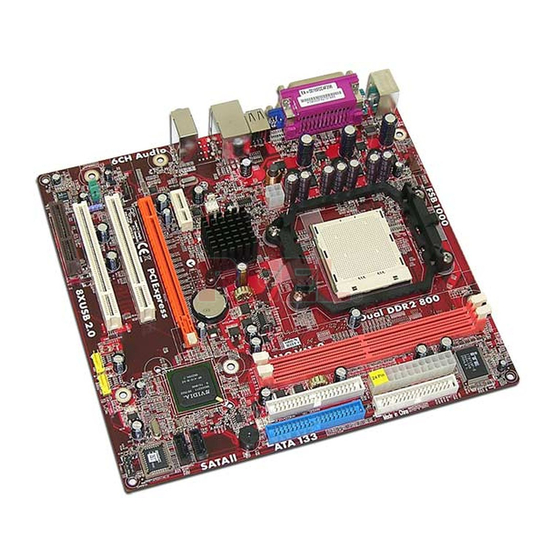
Introducing the Motherboard Introduction Thank you for choosing A11G motherboard of great performance and with enhanced function. This motherboard is designed to fit the AMD AM2 processors in the 940-pin package. Based on the Micro ATX form factor, measuring 244 mm x 224 mm, this motherboard incorporates the following chipsets: C51G Northbridge and MCP51G Southbridge chipsets. -
Page 10: Features
Feature Processor This motherboard uses a Socket AM2 that carries the following features: • Accommodates AMD Sempron/Athlon 64/Athlon 64 X2 Dual-Core/Athlon 64 FX processors • Supports high-performance HyperTransport CPU interface HyperTransport™ Technology is a point-to-point link between two devices, it enables integrated circuits to exchange information at much higher speeds than currently avail- able interconnect technologies. - Page 11 Onboard LAN (optional) The onboard LAN provides the following features: • 10/100 Mbps N-way Auto-negotiation operation • Half/Full duplex capability • Supports Wake-On-LAN(WOL) function and remote wake-up • Integrated 10/100/1000 transceiver • PCI v2.3, 32-bit, 33/66 MHz • Fully compliant with IEEE 802.3, IEEE802.3u and IEEE802.3ab •...
-
Page 12: Motherboard Components
Motherboard Components Introducing the Motherboard... - Page 13 Table of Motherboard Components LABEL COMPONENT 1 CPU_FAN CPU cooling fan connector Socket AM2 for AMD Sempron/Athlon 64/ 2 CPU Socket Athlon 64 X2 Dual-Core/Athlon 64 FX pro- cessors 3 DIMM1~2 240-pin DDR2 SDRAM slots 4 ATX_POWER Standard 24-pin ATX power connector 5 FDD Floppy disk drive connector 6 IDE1...
- Page 14 Memo Introducing the Motherboard...
-
Page 15: Installing The Motherboard
Chapter 2 Installing the Motherboard Safety Precautions • Follow these safety precautions when installing the motherboard • Wear a grounding strap attached to a grounded device to avoid damage from static electricity • Discharge static electricity by touching the metal case of a safely grounded object before working on the motherboard •... -
Page 16: Checking Jumper Settings
Do not over-tighten the screws as this can stress the motherboard. Checking Jumper Settings This section explains how to set jumpers for correct configuration of the motherboard. Setting Jumpers Use the motherboard jumpers to set system configuration options. Jumpers with more than one pin are numbered. -
Page 17: Checking Jumper Settings
Checking Jumper Settings The following illustration shows the location of the motherboard jumpers. Pin 1 is labeled. Jumper Settings Jumper Type Description Setting (default) 1-2: NORMAL 2-3: CLEAR CMOS CLR_CMOS 3-pin CLEAR CMOS Before clearing the CMOS, CLR_CMOS make sure to turn off the sys- tem. -
Page 18: Connecting Case Components
Connecting Case Components After you have installed the motherboard into a case, you can begin con- necting the motherboard components. Refer to the following: Connect the CPU cooling fan cable to CPU_FAN. Connect the system cooling fan connector to SYS_FAN1. Connect the case switches and indicator LEDs to the PANEL1. - Page 19 CPU_FAN: Cooling FAN Power Connectors Signal Name Function System Ground Power +12V +12V Sense Sensor FAN control PWM Users please note that the fan connector supports the CPU cooling fan of 1.1A~2.2A (26.4W max.) at +12V. SYS_FAN: FAN Power Connectors Signal Name Function System Ground...
-
Page 20: Front Panel Header
Front Panel Header The front panel header (PANEL1) provides a standard set of switch and LED headers commonly found on ATX or micro-ATX cases. Refer to the table below for information: Signal Function Signal Function HD_LED_P Hard disk LED(+) 2 FP PWR/SLP *MSG LED(+) HD_LED_N Hard disk LED(-) FP PWR/SLP *MSG LED(-) RST_SW_N Reset Switch(-) -
Page 21: Installing Hardware
Installing Hardware Installing the Processor Caution: When installing a CPU heatsink and cooling fan make sure that you DO NOT scratch the motherboard or any of the surface-mount resistors with the clip of the cooling fan. If the clip of the cooling fan scrapes across the motherboard, you may cause serious damage to the motherboard or its components. -
Page 22: Installing Memory Modules
CPU Installation Procedure The following illustration shows CPU installation components. 1. Install your CPU. Pull up the lever away from the socket and lift up to 90-degree angle. 2. Locate the CPU cut edge (the corner with the pin hold noticeably missing). Align and insert the CPU correctly. - Page 23 Installation Procedure Refer to the following to install the memory modules. This motherboard supports unbuffered DDR2 SDRAM only. Push the latches on each side of the DIMM slot down. Align the memory module with the slot. The DIMM slots are keyed with notches and the DIMMs are keyed with cutouts so that they can only be installed correctly.
- Page 24 Table A: DDR2 (memory module) QVL (Qualified Vendor List) The following DDR2 memory modules have been tested and qualified for use with this motherboard. Type Size Vendor Module Name SAMSUNG K4T56083QF-GCCC DDR2 256MB SAMSUNG K4T5163QB-ZCCC 512MB SAMSUNG K4T51083QB-GCCC AENEON AET560UD00-370A98X AENEON AET560UD00-370A98Z CORSAIR...
- Page 25 Table B: Unbuffered DIMM Support for AM2 CPU Output Driver DRAM Timing Address Timing DIMM1 DIMM2 Compensation Speed Mode Control Register Control Register DDR2-400 002F_2F2Fh X011_1222h DDR2-400 002F_2F2Fh X011_1322h DDR2-533 002F_2F2Fh X011_1222h SRx16 SRx16 SRx16 SRx8 DDR2-533 002F_2F2Fh X011_1322h SRx8 SRx16 DDR2-533 SRx8...
-
Page 26: Installing A Hard Disk Drive/Cd-Rom/Sata Hard Drive
Installing a Hard Disk Drive/CD-ROM This section describes how to install IDE devices such as a hard disk drive and a CD-ROM drive. About IDE Devices Your motherboard has a primary and secondary IDE channel interface (IDE1 and IDE2). An IDE ribbon cable supporting two IDE devices is bundled with the motherboard. You must orient the cable connector so that the pin1 (color) edge of the cable corresponds to the pin 1 of the I/O port connector. - Page 27 About SATA Connectors Your motherboard features two or four SATA connectors supporting a total of two or four drives. SATA refers to Serial ATA (Advanced Technology Attachment) is the standard interface for the IDE hard drives which are currently used in most PCs. These connectors are well designed and will only fit in one orientation.
-
Page 28: Installing A Floppy Diskette Drive
Installing a Floppy Diskette Drive The motherboard has a floppy diskette drive (FDD) interface and ships with a diskette drive ribbon cable that supports one or two floppy diskette drives. You can install a 5.25-inch drive and a 3.5-inch drive with various capacities. The floppy diskette drive cable has one type of connector for a 5.25-inch drive and another type of connector for a 3.5-inch drive. -
Page 29: Installing Add-On Cards
Installing Add-on Cards The slots on this motherboard are designed to hold expansion cards and connect them to the system bus. Expansion slots are a means of adding or enhancing the motherboard’s features and capabilities. With these efficient facilities, you can increase the motherboard’s capabili- ties by adding hardware that performs tasks that are not part of the basic system. - Page 30 Follow these instructions to install an add-on card: Remove a blanking plate from the system case corresponding to the slot you are going to use. Install the edge connector of the add-on card into the expansion slot. Ensure that the edge connector is correctly seated in the slot. Secure the metal bracket of the card to the system case with a screw.
-
Page 31: Connecting Optional Devices
Connecting Optional Devices Refer to the following for information on connecting the motherboard’s optional devices: AUDIO1: Front Panel Audio header This header allows the user to install auxiliary front-oriented microphone and line-out ports for easier access. Signal Name Signal Name Function AUD_MIC Front Panel Microphone input signal... - Page 32 USB3~4: Front Panel USB headers The motherboard has four USB ports installed on the rear edge I/O port array. Additionally, some computer cases have USB ports at the front of the case. If you have this kind of case, use auxiliary USB connector to connect the front-mounted ports to the motherboard. Signal Name Function USBPWR...
-
Page 33: Connecting I/O Devices
Connecting I/O Devices The backplane of the motherboard has the following I/O ports: PS2 Mouse Use the upper PS/2 port to connect a PS/2 pointing device. PS2 Keyboard Use the lower PS/2 port to connect a PS/2 keyboard. Parallel Port (LPT1) Use LPT1 to connect printers or other parallel communications devices. - Page 34 Installing the Motherboard...
-
Page 35: Using Bios
Chapter 3 Using BIOS About the Setup Utility The computer uses the latest Award BIOS with support for Windows Plug and Play. The CMOS chip on the motherboard contains the ROM setup instructions for configuring the motherboard BIOS. The BIOS (Basic Input and Output System) Setup Utility displays the system’s configura- tion status and provides you with options to set system parameters. - Page 36 Press DEL to enter SETUP Press the delete key to access the BIOS Setup Utility. Phoenix-Award WorkstationBIOS CMOS Setup Utility Standard CMOS Features Load Fail-Safe Defaults Load Optimized Defaults Advanced BIOS Features Advanced Chipset Features Set Supervisor Password Integrated Peripherals Set User Password Power Management Setup Save &...
-
Page 37: Updating The Bios
Updating the BIOS You can download and install updated BIOS for this motherboard from the manufacturer’s Web site. New BIOS provides support for new peripherals, improvements in performance, or fixes for known bugs. Install new BIOS as follows: If your motherboard has a BIOS protection jumper, change the setting to allow BIOS flashing. -
Page 38: Standard Cmos Features
Standard CMOS Features This option displays basic information about your system. Phoenix - Award WorkstationBIOS CMOS Setup Utility Standard CMOS Features Date (mm:dd:yy) Fri, Jan 3 2006 Item Help 0 : 3 : 51 Time (hh:mm:ss) IDE Channel 0 Master [ None] IDE Channel 0 Slave [ None]... - Page 39 IDE HDD Auto-Detection Press <Enter> while this item is highlighted to prompt the Setup Utility to automatically detect and configure an IDE device on the IDE channel. If you are setting up a new hard disk drive that supports LBA mode, more than one line will appear in the parameter box.
-
Page 40: Advanced Bios Features
Advanced BIOS Features This option defines advanced information about your system. Phoenix - Award WorkstationBIOS CMOS Setup Utility Advanced BIOS Features CPU Feature [Press Enter] Item Help Removable Device Priority [Press Enter] Hard Disk Boot Priority [Press Enter] Menu Level Network Boot Priority [Press Enter] CPU Internal Cache... - Page 41 Removable Device Priority (Press Enter) Scroll to this item and press <Enter> to view the following screen: Phoenix-Award WorkstationBIOS CMOS Setup Utility Removable Device Priority Item Help 1. Floppy Disks Menu Level Use < > or < > to select a device, then press <+>...
- Page 42 Network Boot Priority (Press Enter) Scroll to this item and press <Enter> to view the following screen: Phoenix-Award WorkstationBIOS CMOS Setup Utility Network Boot Priority Item Help 1. Network 0: NVIDIA Boot Agent 224.0523 Menu Level Use < > or < >...
-
Page 43: Advanced Chipset Features
Typematic Rate Setting (Disabled) If this item is enabled, you can use the following two items to set the typematic rate and the typematic delay settings for your keyboard. • Typematic Rate (Chars/Sec): Use this item to define how many characters per second are generated by a held-down key. - Page 44 Onboard GPU (Enable If No Ext GPU) This item enables the onboard GPU function. Disable this item if you are going to install an external GPU. Frame Buffer Size (64M) This item enables users to specify the Onboard VGA share memory size. CPU Frequency (200.0) This item enables users to manually over-clock the CPU frequency, ranging from 200.0 to 300.0.
-
Page 45: Integrated Peripherals
Integrated Peripherals These options display items that define the operation of peripheral components on the system’s input/output ports. Phoenix - Award WorkstationBIOS CMOS Setup Utility Integrated Peripherals Item Help IDE Function Setup [Press Enter] RAID Config [Press Enter] Menu Level Onboard Device [Press Enter] Super IO Device... - Page 46 Primary/Seconday Master/Slave UDMA (Auto) Each IDE channel supports a master device and a slave device. This motherboard supports UltraDMA technology, which provides faster access to IDE devices. If you install a device that supports UltraDMA, change the appropriate item on this list to Auto.
- Page 47 Onboard Device (Press Enter) Scroll to this item and press <Enter> to view the following screen: Phoenix - Award WorkstationBIOS CMOS Setup Utility Onboard Device Item Help OnChip USB [V1.1+V2.0] USB Legacy Support [Enabled] Menu Level USB Mouse Support [Enabled] AC97/HD Audio [Auto] MC97 Modem...
- Page 48 Super IO Device (Press Enter) Scroll to this and press <Enter> to view the following screen: Phoenix - Award WorkstationBIOS CMOS Setup Utility SuperIO Device Item Help Onboard FDC Controller [Enabled] Onboard Serial Port 1 [3F8/IRQ4] Onboard Parallel Port [378/IRQ7] Menu Level Parallel Port Mode [ECP]...
-
Page 49: Power Management Setup
Power Management Setup This option lets you control system power management. The system has various power- saving modes including powering down the hard disk, turning off the video, suspending to RAM, and software power down that allows the system to be automatically resumed by certain events. - Page 50 Video Off Method (DPMS Support) This item defines how the video is powered down to save power. This item is set to DPMS (Display Power Management Software) by default. HDD Power Down (Disabled) The IDE hard drive will spin down if it is not accessed within a specified length of time. Options are from 1 Min to 15 Min and Disable.
-
Page 51: Pnp/Pci Configurations
PnP/ PCI Configurations This section describes configuring the PCI bus system. PCI (Peripheral Component Inter- connect) is a system, which allows I/O devices to operate at speeds nearing CPU’s when they communicate with own special components. All the options describes in this section are important and technical and it is strongly recommended that only experienced users should make any changes to the default settings. -
Page 52: Pc Health Status
PC Health Status On motherboards that support hardware monitoring, this item lets you monitor the param- eters for critical voltages, critical temperatures, and fan speeds. Phoenix - Award WorkstationBIOS CMOS Setup Utility PC Health Status Item Help Smart Fan Function [Press Enter] Shutdown Temperature [Disabled]]... -
Page 53: Load Fail-Safe Defaults
• FAN1 START PWM VALUE: This item is used to set the start PWM value of the smart fan. • FAN1 START Temp C: This item is used to set the start temperature of the smart fan. • FAN1 Limit Temp This item is used to set the limit temperature of the smart fan. -
Page 54: Load Optimized Defaults
Load Optimized Defaults This option opens a dialog box that lets you install optimized defaults for all appropriate items in the Setup Utility. Press <Y> and then <Enter> to install the defaults. Press <N> and then <Enter> to not install the defaults. The optimized defaults place demands on the system that may be greater than the performance level of the components, such as the CPU and the memory. -
Page 55: Using The Motherboard Software
Chapter 4 Using the Motherboard Software About the Software CD-ROM The support software CD-ROM that is included in the motherboard package contains all the drivers and utility programs needed to properly run the bundled products. Below you can find a brief description of each software program, and the location for your motherboard version. -
Page 56: Running Setup
Setup Tab Setup Click the Setup button to run the software installation program. Select from the menu which software you want to install. Browse CD The Browse CD button is the standard Windows command that allows you to open Windows Explorer and show the contents of the support Before installing the software from Windows Explorer, look for a file named README.TXT, INSTALL.TXT or something similar. - Page 57 Click Next. The following screen appears: Check the box next to the items you want to install. The default options are recommended. Click Next run the Installation Wizard. An item installation screen appears: Follow the instructions on the screen to install the items. Drivers and software are automatically installed in sequence.
-
Page 58: Manual Installation
Manual Installation Insert the CD in the CD-ROM drive and locate the PATH.DOC file in the root directory. This file contains the information needed to locate the drivers for your motherboard. Look for the chipset and motherboard model; then browse to the directory and path to begin installing the drivers.
Need help?
Do you have a question about the A11G and is the answer not in the manual?
Questions and answers