Table of Contents
Advertisement
Quick Links
Advertisement
Table of Contents

Related Manuals for PAW SolarBloC midi Basic


Summary of Contents for PAW SolarBloC midi Basic
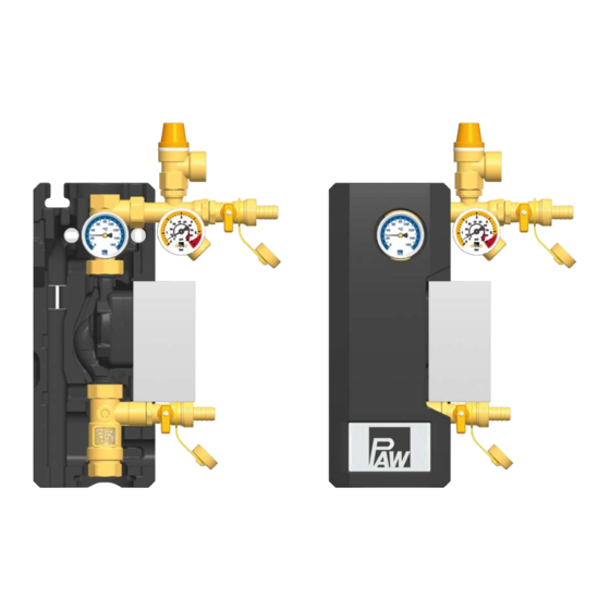
- Page 1 PAW GmbH & Co. KG Böcklerstr. 11, 31789 Hameln, Germany Phone: +49-5151-9856-0, Fax: +49-5151-9856-98 E-mail: info@paw.eu, Web: www.paw.eu Installation and Operation Instructions return station SolarBloC® midi Basic - DN 20 SolarBloC® maxi Basic - DN 25 09/2023 9976x0210x-mub-en - V02...
-
Page 2: Table Of Contents
Table of Contents Table of Contents General Information....................3 About these instructions....................3 About this product......................3 Designated use......................4 Safety instructions......................5 Mounting and installation [specialist]]..............7 Commissioning [specialist]..................10 Flushing and filling the solar circuit................11 Preparations before flushing..................13 Flushing and filling.....................13 Setting the solar installation..................15 Maintenance [specialist].................... -
Page 3: General Information
General Information 1 General Information Carefully read these instructions before installation and commissioning. Save these instructions in the vicinity of the installation for future reference. 1.1 About these instructions These instructions describe the function, installation, commissioning and operation of the return stations SolarBloC®... -
Page 4: Designated Use
Due to its design, the station may only be installed and operated as described in these instructions! Only use PAW accessories with the solar station. Improper usage excludes any liability claims. -
Page 5: Safety Instructions
Safety instructions 2 Safety instructions The installation and commissioning as well as the connection of electrical components require technical knowledge commensurate with a recognised vocational qualification as a fitter for plumbing, heating and air conditioning technology, or a profession requiring a comparable level of knowledge [specialist]. - Page 6 Safety instructions CAUTION Personal injury and material damage due to overpressure! Closing both ball valves in the primary circuit will separate the safety group from the heat exchanger. A rise in temperature in the storage tank may result in high pressures, which may lead to personal injury and material damage! Only close the ball valves for service and maintenance.
-
Page 7: Mounting And Installation [Specialist]]
Mounting and installation [specialist]] 3 Mounting and installation [specialist]] NOTICE Material damage due to high temperatures! Since the solar fluid near the collector can be very hot, the group of fittings must be installed at a sufficient distance from the collector field. It may be necessary to install an intermediate tank in order to protect the expansion tank. - Page 8 Mounting and installation [specialist]] 1. Remove the station from the packaging. 2. Remove the insulating front shell. 3. Only for version with Wilo Para MAXO pump / Grundfos Solar PML pump: Mount the enclosed safety group for completion and prior to commissioning.
- Page 9 Mounting and installation [specialist]] 6. Connect the solar station to the installation by using the pipes ① Return to the collector field ③ Return from the storage tank All thread connections have ¾" internal threads for DN 20 and 1" internal threads for DN 25. 7.
-
Page 10: Commissioning [Specialist]
Commissioning [specialist] 4 Commissioning [specialist] Please observe the following safety instructions regarding the commissioning of the station: WARNING Risk of burning and scalding! The valves and fittings may heat up to more than 100 °C. Therefore, do not clean or fill the system when the collectors are hot (intense sunshine). -
Page 11: Flushing And Filling The Solar Circuit
Commissioning [specialist] 4.1 Flushing and filling the solar circuit The fill and drain valves necessary to flush and fill the installation are integrated in the solar station. Make sure not to wash dirt particles that may be present in the solar installation into the expansion tank. - Page 12 Commissioning [specialist] Functions of the fill and drain valve within the safety group Position Function Position "closed" (station in operation): Fill and flush circuit is closed. Pressure gauge indicates system pressure. Position "open" (fill and flush processes): Fill and flush circuit is open. Pressure gauge indicates pressure. Position "maintenance"...
-
Page 13: Preparations Before Flushing
Commissioning [specialist] 4.2 Preparations before flushing The solar circuit is flushed in the direction of flow. 1. Disconnect the expansion tank from the solar system. Observe the separate instructions for the expansion tank! 2. Close the return ball valve [1.2] (90°, see chapter 4.1). - Page 14 Commissioning [specialist] 5. Close the drain valve [3.2] while the filling pump is running and increase the system pressure to about 5 bars. The system pressure is displayed on the pressure gauge. Close the fill valve [1.4] by turning it into position "closed" (see chapter 4.1) and switch off the pump of the flush and fill station.
-
Page 15: Setting The Solar Installation
Commissioning [specialist] 4.4 Setting the solar installation 1. Set the desired revolution speed of the solar pump depending on the required flow rate. If necessary, the flow rate can be reduced by the ball valve [3.1] (only necessary if the pump is not speed-controlled). -
Page 16: Maintenance [Specialist]
Maintenance [specialist] 5 Maintenance [specialist] WARNING Risk of burning and scalding! The valves and fittings and the solar fluid can have temperatures of more than 100 °C. The solar fluid may escape as vapour and result in scalding. Perform maintenance work only when the collector temperatures are ►... -
Page 17: Draining The Solar System
Maintenance [specialist] 5.2 Draining the solar system 1. Switch off the controller and secure it against being switched on again. 2. Open the check valve in the return ball valve [1.2] by turning the ball valve into position 45° (see chapter 4.1). Open the check valve possibly present in the flow line. -
Page 18: Deinstallation
Maintenance [specialist] 5.3 Deinstallation 1. Drain the solar installation as described in the previous chapter. 2. Disconnect the pipe connections to the solar installation. 3. To remove the solar station from the mounting plate, pull out the clip springs laterally with a screwdriver. 4. -
Page 19: Scope Of Delivery [Specialist]
Scope of delivery [specialist] 6 Scope of delivery [specialist] NOTICE Serial number Complaints and requests/orders of spare parts will only be processed with information on the serial number! The serial number is placed on the safety group. In case of a complaint, please send us the entirely completed commissioning report. ►... - Page 20 Scope of delivery [specialist] Position Spare part Item number Pressure relief valve ½" x ¾", 6 bars N00300 Pressure gauge 0-6 bars, G ¼" axial; d = 50 mm, 130 °C N00337 Alternative pumps: Wilo Para ST 15/7 N00150 Wilo Para ST 15/13 N00299 Grundfos UMP3 Solar 15-75 N00025...
-
Page 21: Solarbloc® Maxi Basic Dn 25
Scope of delivery [specialist] 6.2 SolarBloC® maxi Basic DN 25 Position Spare part Item number Pressure relief valve ½" x ¾", 6 bars N00300 Pressure gauge 0-6 bars, G ¼" axial; d = 50 mm, 130 °C N00337 Union nut G 1½", wrench size 52 N00269 09/2023 9976x0210x-mub-en - V02... - Page 22 Scope of delivery [specialist] Position Spare part Item number Alternative pumps: Wilo Para ST 25/8 N00263 Grundfos UPM3 Solar 25-75 N00035 Grundfos UPM3 Solar 25-145 N00304 Flowmeter 1", 5-40 l/min, 1½" union nut x 1" int. thread x ½" int. N00227 thread with fill and drain valve and seal Sealing kit, 10 pieces, 1", for thread connection 1½"...
-
Page 23: Solarbloc® Maxi Basic Dn 25 For Grundfos Solar Pml And Wilo Para Maxo
Scope of delivery [specialist] 6.3 SolarBloC® maxi Basic DN 25 for Grundfos Solar PML and Wilo Para MAXO Position Spare part Item number Sealing kit 24.0 x 17.0 x 2.0, ¼", for thread connection ¾", 10 pieces N00030 Pressure relief valve ½" x ¾", 6 bars N00300 Pressure gauge 0-6 bars, G ¼"... - Page 24 Scope of delivery [specialist] Position Spare part Item number Sealing kit, 44.0 x 32.0 x 2.0, 1", for thread connection 1½", 10 pieces N00036 Alternative pumps: Wilo Para MAXO 25-180-11-F02 N00253 Grundfos Solar PML 25-145 N00226 Flowmeter 1", 5-40 l/min, 1½" union nut x 1" int. thread x ½" int. N00227 thread with fill and drain valve and seal Return ball valve DN 25, F1“...
-
Page 25: Technical Data
Technical data 7 Technical data Dimensions SolarBloC® midi DN 20 SolarBloC® maxi DN 25 Height (with pressure relief valve) 383 mm 474 mm Width (with fill and drain valve) 244 mm 246 mm / 286 mm (Wilo MAXO and Grundfos Solar PML) Depth (with insulation) 150 mm... -
Page 26: Dimensional Drawing Solarbloc® Midi Basic Dn 20
Technical data 7.1 Dimensional drawing SolarBloC® midi Basic DN 20 7.2 Dimensional drawing SolarBloC® maxi Basic DN 25 9976x0210x-mub-en - V02 09/2023... -
Page 27: Pressure Drop And Pump Characteristic Curves Solarbloc® Midi Basic Dn 20
Technical data 7.3 Pressure drop and pump characteristic curves SolarBloC® midi Basic DN 20 7.4 Pressure drop and pump characteristic curves SolarBloC® maxi Basic DN 25 09/2023 9976x0210x-mub-en - V02... -
Page 28: Function Of The Check Valves [Expert]
Function of the check valves [Expert] 8 Function of the check valves [Expert] The check valves in this station prevent unwanted gravity circulation within their range of use. The functioning of the check valves depends: on the system height ● on the temperature difference between storage tank and collector ●... - Page 29 Function of the check valves [Expert] Do you need to know it exactly? The density of the solar fluid strongly decreases with increasing temperature. In systems of high system heights and with large temperature differences, the difference in density causes gravity circulation.
-
Page 30: Disposal
Disposal 9 Disposal NOTICE Electrical and electronic devices must not be disposed of in the household waste. For your return, there are free collection points for electrical appliances and, if necessary, additional points of acceptance for the reuse of the devices in your area. The addresses can be obtained from your city or communal administration. -
Page 31: Commissioning Report
Commissioning report 10 Commissioning report System operator Location of installation Collectors (number / type) Collector surface m² System height m (height difference between the station and the collector field) Pipeline Diameter = length = Venting (collector field) manual vent valve automatic vent valve vented Bleeding device (station) - Page 32 Böcklerstr. 11 31789 Hameln, Germany Translation of the original instructions www.paw.eu We reserve the right to make technical changes without notice! Phone: +49-5151-9856-0 Printed in Germany – Copyright by PAW GmbH & Co. KG Fax: +49-5151-9856-98 09/2023 9976x0210x-mub-en - V02...
Need help?
Do you have a question about the SolarBloC midi Basic and is the answer not in the manual?
Questions and answers