Table of Contents
Advertisement
Quick Links
Advertisement
Table of Contents

Subscribe to Our Youtube Channel
Related Manuals for TERRATEST 4000 STREAM


Summary of Contents for TERRATEST 4000 STREAM
- Page 1 Instruction Manual ‘TERRATEST 4000 STREAM’ ‘TERRATEST 6000 BLE’ Made in Germany...
- Page 3 Phone.: +49 3301 700 700 · Fax: + 49 3301 55 44 0 www.terratest.de · info@terratest.de TERRATEST GmbH ensures constant improvement and development of its products and hence reserves the right to make changes to its products at any time, and without prior notice.
-
Page 4: Table Of Contents
Changing the Paper ........36 Test Execution ‘TERRATEST 6000 BLE’ ......38 Preparing the Testing Point . - Page 5 App ‘TERRATEST’ ........
-
Page 6: Documentation
TERRATEST GmbH cannot be held liable for errors contained in this documentation, or for accidental or sequential damage in connection with the delivery, performance, or use of the material. -
Page 7: General Safety Information
CAUTION Never place or charge the testing computer or load plate of ‘TERRATEST 6000 BLE’ in areas with excessive humidity, high temperatures, direct sunlight, or close to open flames. Doing so carries the risk of fire or electric shock. -
Page 8: Safety Precautions During Power Supply
(-) pole of the battery. The cable contains a 2A/32V fuse. Only the permanently-installed, long-lasting, rechargeable battery pack approved by the manufacturer (type 8904 7.4 V/2.4 Ah) should be used in the Bluetooth sensor dome ‘TERRATEST 6000 BLE’. This bat- ® tery pack should only be replaced by the manufacturer. -
Page 9: Safety Precautions During Operation
1.4. Safety Precautions during Operation ATTENTION TERRATEST GmbH shall not be liable for any damage, consequential damage, or financial loss that occurs as a result of improper use of the device and / or lack of professional knowledge when evaluating the test data. - Page 10 For more information about collection points for electronic waste please contact your city council, your public waste management authorities, or your garbage disposal service. TERRATEST GmbH will take back electronic waste free of charge, and dispose of it in a safe and environmentally appropriate manner.
-
Page 11: Packaging
Please also advise TERRATEST GmbH of the damage and the name of the carrier, so that we can also get in contact with the transport company. -
Page 12: Contents Of Delivery
Magnetic plate ‘TRETMINE’, for the convenient placement of the loading device on the ground ■ STREAM dongle for storage and wireless transmission of measuring results to TERRATEST App ■ Extension cable, load plate / testing computer, for extended range as well as tests in areas that are difficult to access such as trenches etc. -
Page 13: Basic Package 'Terratest 6000 Ble
2.3 Basic Package ‘TERRATEST 6000 BLE’ Light Weight Deflectometer 10 kg corresponding to German standard TP BF-StB Part B 8.3 ‘TERRATEST 6000 BLE’ with integrated GPS system and Google Maps interface ® consisting of: ■ 10 kg loading device with ergonomic weight-catching grip ■... -
Page 14: General View 'Terratest 4000 Stream
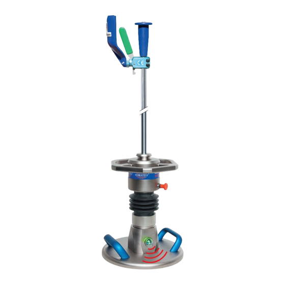
2.5 General View – ‘TERRATEST 4000 STREAM’ release mechanism impact protector guide rod release lever inspection window electronic mechanical testing computer loading device handle storage box weight-catching grip GPS antenna (not visible) USB cable port... -
Page 15: Top View Of Control Panel, Testing Computer 'Terratest 4000 Stream
2.6 Top View of Control Panel, Testing Computer – ‘TERRATEST 4000 STREAM’ GPS antenna USB stick port, also USB cable port charging socket STREAM dongle (on the back panel) /max. 1.25A button for paper feed control buttons backlit graphic display with... -
Page 16: General View 'Terratest 6000 Ble
2.7 General View – ‘TERRATEST 6000 BLE’ release mechanism impact protector guide rod release lever inspection window electronic mechanical testing computer loading device handle storage box weight-catching grip GPS antenna (not visible) USB cable port... -
Page 17: Top View Of Control Panel, Testing Computer 'Terratest 6000 Ble
2.8 Top View of Control Panel, Testing Computer – ‘TERRATEST 6000 BLE’ GPS antenna USB cable port USB-Stick port charging socket (on the back panel) 12V /max. 1,25A button for paper feed control buttons backlit graphic display with model designation... -
Page 18: Technical Specifications
3. Technical Specifications 3.1 Device Designation: ‘TERRATEST 4000 STREAM’ with box for testing computer ‘Robusta’ (box made of flight case material, and aluminium profiles, external button on the front face) Model designation on acrylic glass lid and on start display ‘TERRATEST 6000 BLE’... -
Page 19: Load Plate
95 dB(A) 95 dB(A) Sound pressure level 84 dB(A) 84 dB(A) 3.5 Testing Computer Weight without accessories ‘TERRATEST 4000 STREAM’ 4,2 kg Weight without accessories ‘TERRATEST 6000 BLE’ 4,1 kg Dimensions length = 240 mm width = 230 mm height = 230 mm... -
Page 20: Power Supply
(basic package). A long-lasting, rechargeable, built-in battery pack type 8904 7.4 V/2.4 Ah is located in the sensor dome ‘TERRATEST 6000 BLE’. It should be charged with the supplied power cable 9V DC/2A with plugs from LEMO. -
Page 21: Charging Of Testing Computer
Load Plate ‘TERRATEST 6000 BLE’ ® To charge the battery pack in the Bluetooth load plate (‘TERRATEST 6000 BLE’), the item must be swit- ® ched OFF. Use the supplied charging cable with LEMO plug and insert it into the LEMO connector of the Bluetooth load plate. - Page 22 When disconnecting the cable always take hold of the plug. Pulling on the cable may result in damage to the wires. The power cable for the Bluetooth load plate ‘TERRATEST 6000 ® BLE’ is equipped with a plug with LEMO ‘PUSH-PULL’ lock and anti-kink protection.
-
Page 23: Usb Cable Port
Car Charger for Testing Computer: Only the car charger supplied by the manufacturer type MWCP1 (712026) should be used. Charge the device only in dry, indoors locations (e.g. inside vehicles). The inner pole is the positive (+) pole. Type MWCP1 (712026) inner pole positive (+) Fuse T2A F (6.3mm x 32mm) First plug the power cable into the appropriate ‘12V... -
Page 24: Measuring Cable
3.12 Measuring Cable ‘TERRATEST 4000 STREAM’: The measuring cable for transferring the sensor signals to the testing com- puter can be extended to a maximum of 2.5 meters. It is equipped with two identical 6.35 mm jack plugs. Never pull on the measuring cable to disconnect the plug-socket connection; doing so may cause dama- ge to the cable and/or socket. - Page 25 Use only the measuring cables provided. Failure to do so may cause fire or electric shock. When closing the lid of the testing computer, take care not to trap the measuring cable. Female socket Male plug ‘TERRATEST 4000 STREAM’...
-
Page 26: General Overview: Light Weight Deflectometer
■ ‘Continuous measuring mode’ for quick performance of several tests without additional operation of the testing computer, when multiple testing points are close to each other (‘TERRATEST 6000 BLE’) ■ Text input function to add notes about material or altitude of the testing point ■... -
Page 27: Dynamic Plate Load Test
4.3 Dynamic Plate Load Test The dynamic plate load test with the Light Weight Deflectometer is a test method during which the ground is subjected to an impact load. This impact load is caused by a weight dropping onto a load plate with a diameter of 30 cm (radius r = 15 cm), which generates a maximum force (F max ) of 7.070 kN. -
Page 28: Calibration
4.5 Calibration Before delivery ‘TERRATEST 4000 STREAM’ and ‘TERRATEST 6000 BLE’ are in standard calibrated accor- ding to German ‘Technical Test Code for Soil and Rock Mechanics in Road Constructions TP BF-StB Part B 8.4’. Calibration acc. to Austrian Test Specification RVS 08.03.04 is also available as an option. During calibration all components of the device, such as the load plate with integrated sensor, the loading device and the electronic testing computer, are attuned specifically to one another. -
Page 29: Proposal For The Correlation Of
German Federal Road Research Institute (Bundesanstalt für Straßenbau). Send the device back to TERRATEST GmbH for calibration at least once a year, otherwise test results may be imprecise. Test results of a device that has not been calibrated, or of a device with an expired calibration date, must not be used for evaluating the bearing capacity of soil and rock. - Page 30 For every static plate load test at least three dynamic tests must be performed. TERRATEST GmbH shall not be liable for any damage, consequential damage, or even financial loss that occurs as a result of improper use of the device and / or lack of professional knowledge when evaluating the test data.
-
Page 31: Determining The Residual Compaction
4.9 Determining the Residual Compaction If three individual curves are shown on the protocol printout (see Figure 1) and if the Smax value of the individual settlements decreases significantly, re-compaction has occurred caused by the test; further compaction work is usually necessary. In this case we recommend improving the compaction at the same place by performing 15 more impact drops with the Light Weight Deflectometer. -
Page 32: Test Execution 'Terratest 4000 Stream
F R 3 0 / 0 6 / 1 7 1 5 : 5 0 : 2 2 acknowledges availability by ‘OK’ in the display, and the voice output by ‘Welcome to TERRATEST. Sensor OK. Start test’ If one of these features is unavailable, display shows ‘?’ instead. Absent sensor connection is noti- fied by voice output ‘No sensor’. - Page 33 Regularly check that the transportation lock of the drop weight is functioning properly. If you notice signs of wear, stop using the device immediately. Send the device back to TERRATEST GmbH for the transportation lock to be repai- red or replaced.
- Page 34 Put on hearing protectors before the first drop. Hearing protectors must be worn when operating the Light Weight Deflectometer, since the noise level may rise over 85 dB during the test. ATTENTION: Operating the device without hearing protection can result in permanent hearing impairment. Following the instruction by voice output ‘FIRST PRELOAD’, and display LFG 1.0 instruction ‘LFG 1.0 1.
- Page 35 A longer audio signal (a beep lasting 1 second) and the voice message ‘TEST COMPLETED. LAY DOWN WEIGHT AT THE BOTTOM’ informs the user about the end of the test, and about registration of the measurement in the internal memory and on USB stick (if plugged in). All test data including sett- lement curves, GPS coordinates, date, time, serial number, device type, and the test results themselves, are now saved.
-
Page 36: Printing The Test Protocol
Use only thermal paper; the coated, heat-sensitive side must face outwards. Suitable paper rolls can be obtained in most office supply During the printing stores, or ordered at TERRATEST GmbH. process the control lamp will show green. Specifications of paper rolls:... - Page 37 Printout of the Test Protocol serial number device name device type German standard time of test date of test GPS coordinates of testing point dynamic deflection module zero point test area progress of settlement with the three settlement curves maximum settlement maximum speed of immersion average...
-
Page 38: Test Execution 'Terratest 6000 Ble
F R 3 0 / 0 6 / 1 7 1 5 : 5 0 : 2 2 acknowledges availability by ‘OK’ in the display, and the voice output by ‘Welcome to TERRATEST. Sensor OK. Start test’ If one of these features is unavailable, display shows ‘?’ instead. Absent sensor connection is noti- fied by voice output ‘No sensor’. - Page 39 LOCK Regularly check that the transportation lock of the drop weight is functioning properly. If you notice signs of wear, stop using the device immediately. Send the device back to TERRATEST for the transportation lock to be repaired or replaced.
- Page 40 Put on hearing protectors before the first drop. Hearing protectors must be worn when operating the Light Weight Deflectometer, since the noise level may rise over 85 dB during the test. ATTENTION: Operating the device without hearing protection can result in permanent hearing impairment. When Bluetooth connection is established, the Status LED of the Bluetooth ®...
- Page 41 After performing the third test, the device will show the settlements s4, s5 and s6 in mm, as well as the respective settlement curves. Additionally, the final result, the Evd value in MN/m , will be shown and will also be announced, rounded to whole numbers in MN/m , via the voice output.
-
Page 42: The 'Magic Eye' Of The Bluetooth Sensor Dome
6.3 The ‘Magic Eye’ of the Bluetooth Sensor Dome ® The Bluetooth transmission unit of the Bluetooth sensor dome is equipped ® ® with a status LED, which indicates three different states. During the test, these are displayed via the ‘magic eye’ (a transparent hemispherical cover over the transmitter) on the Bluetooth sensor dome. -
Page 43: Continuous Measuring Mode
‘Magic Eye’ start to flash ten times in Red with the Bluetooth load plate ® switching OFF, the battery pack is defective and must be replaced. Consult TERRATEST customer support. ® 6.4 Continuous Measuring Mode F R 3 0 / 0 6 / 1 7 1 5 : 5 0 : 2 2 If the test shall be performed on several testing points close to each other, the testing computer can be operated in ‘CONTINUOUS MEASURING... -
Page 44: Printing The Test Protocol
Use only thermal paper; the coated, heat-sensitive side must face During the printing outwards. Suitable paper rolls can be obtained in most office supply stores, or ordered at TERRATEST GmbH. process the control lamp will show green. Specifications of paper rolls:... - Page 45 Printout of the Test Protocol serial number device name device type German standard time of test date of test GPS coordinates of testing point dynamic deflection module zero point test area progress of settlement with the three settlement curves maximum settlement maximum speed of immersion average...
-
Page 46: Menu Guidance
7. Menu Guidance F R 3 0 / 0 6 / 1 7 1 5 : 5 0 : 2 2 7.1 Menu ‘USB STICK’ All commercially available USB sticks can be used. However, pay 6 , 3 V attention to the height of the USB stick; if it has a height over 45 mm, it could cause damage to the testing computer when closing the cover. -
Page 47: Subsequent Printing Of Test Data
→ 7.2 Subsequent Printing of Test Data USB STICK Turn on the device by pressing the ‘START’ button. Then enter the ‘MAIN LANGUAGE GPS / TIME MENU’ by pressing the ‘SELECT’ button. Use the ‘SELECT’ button to INTERNAL MEMORY move the arrow and select ‘USB STICK’ from the menu. Press the SERVICE SENSOR ‘START’... -
Page 48: Language Menu
7.3 Language Menu USB-STICK → Turn on the device by pressing the ‘START’ button. Then enter the ‘MAIN LANGUAGE GPS / TIME MENU’ by pressing the ‘SELECT’ button. Use the ‘SELECT’ button to INTERNAL MEMORY move the arrow and select ‘LANGUAGE’ from the menu. Then press the SERVICE SENSOR ‘START’... -
Page 49: Menu Gps / Time
7.4 Menu GPS / TIME F R 3 0 / 0 6 / 1 7 1 5 : 5 0 : 2 2 7.4.1 GPS Reception The device is delivered with the status set to ‘GPS IS ON’. 6 , 3 V 1 0 0 The GPS reception is automatically activated when turning on the device, GPS NOT AVAILABLE... -
Page 50: Gps On / Gps Off
7.4.3 GPS ON / GPS OFF USB STICK Turn on the device by pressing the ‘START’ button. Then enter the ‘MAIN LANGUAGE → GPS / TIME MENU’ by pressing the ‘SELECT’ button. Use the ‘SELECT’ button to INTERNAL MEMORY move the arrow and select ‘GPS / TIME’ from the menu. Press the SERVICE SENSOR ‘START’... -
Page 51: Date And Time
7.4.5 Date and Time USB STICK The device is delivered with the status set to ‘TIME IS GPS TIME’. Weekday, LANGUAGE → GPS / TIME date and switch-on time will be shown automatically during ‘STATUS INTERNAL MEMORY REQUEST’, when turning on the device. This data is globally imported via SERVICE SENSOR satellite;... -
Page 52: Time Zones
7.4.7 Time Zones USB STICK The testing computer is delivered with the time zone set to ‘GMT + 01:00 h’ LANGUAGE → GPS / TIME (GMT = Greenwich Mean Time). This setting corresponds to Central INTERNAL MEMORY European Winter Time, imported via the corresponding satellites by the SERVICE SENSOR GPS receiver. -
Page 53: Internal Memory
Position the arrow on ‘SEND TO PC’ , and press the ‘START’ button(SET) PRINT OUT → SEND TO PC to load test data directly to ‘TERRATEST.Utility’ (refer to page 67 ff). SEND TO CARD Establish the USB connection between the testing computer and PC by ERASE MEMORY plugging in the USB cable included in the basic package. -
Page 54: Internal Memory To External Media
Launch the software ‘TERRATEST.Utility’ and click on field ‘Read Files’ under tab ‘Testing computer’. All data records saved in the internal memory will then be copied to the PC. (page 69) You can then underta- ke an analysis of the test data on your PC. All test data will be retained in the internal memory. -
Page 55: Service
7.6 Service USB STICK LANGUAGE GPS / TIME 7.6.1 Input Test INTERNAL MEMORY → Turn on the device by pressing the ‘START’ button. Enter the ‘MAIN SERVICE SENSOR MENU’ by pressing the ‘SELECT’ button. Use the ‘SELECT’ button to → EXIT move the arrow and select ‘SERVICE’... -
Page 56: Device Type Lfg / Mfg
7.6.3 Device Type LFG / MFG INPUTTEST Turn on the device by pressing the ‘START’ button. Enter the ‘MAIN VERSION → LFG / MFG MODE MENU’ by pressing the ‘SELECT’ button. Use the ‘SELECT’ button to DISPLAY CONTRAST move the arrow and select ‘SERVICE’ from the menu. Press the ‘START’ SOUND SERVICE PRINT DATA button (SET) to enter the ‘SERVICE’... -
Page 57: Voice Output: Sound Service
‘TEST SOUND’ or ‘TEST NEXT SOUND’ from the menu. Press the ‘START’ button (SET). A voice instruction in the selected volume will follow. The menu entry ‘LOAD FILES’ permits TERRATEST GmbH to install other language versions (if available). Only one language per device can be used at a time. -
Page 58: Print Data
7.6.6 Print Data INPUTTEST VERSION ‘Print Data’ offers an additional possibility to enter company or order LFG / MFG MODE data as well as conversion factors to Ev 2 or Ev 1 determined by correla- DISPLAY CONTRAST SOUND SERVICE tion measurement (refer to page 29, Proposal for Correlation of →... -
Page 59: Ev1 Factor / Ev2 Factor
Pressing ‘RESET/OFF’ once more opens the MAIN menu, and pressing a third time returns to ‘STATUS REQUEST’. Press ‘START’ to initi- ate measurement. 7.6.7 PC-Remote The function PC REMOTE is reserved for factory settings and calibration mode, accessible only for TERRATEST personnel. -
Page 60: Load Plate
7.7 Load Plate USB STICK LANGUAGE GPS / TIME 7.7.1 Stand-by Time INTERNAL MEMORY The testing computer can be operated in two measuring modes: ‘SINGLE SERVICE → SENSOR MEASURING MODE’ and ‘CONTINUOUS MEASURING MODE’. If several → EXIT tests shall be performed in a limited period of time, it is useful to set the MAIN MENU testing computer to ‘CONTINUOUS MEASURING MODE’. -
Page 61: Calibration Reminder
IN 21 DAYS zed institution. TERRATEST is qualified for this service and has obtained ® the admission. During each calibration, the expiration date is entered in the measuring electronics (refer to point 7.6.2, page 55) and noted on the... -
Page 62: Analysis Software 'Teolo
8. Analysis Software ‘TEOLO’ To evaluate the measuring results on PC, TERRATEST offers a web-based software under www.terratest.de. ® The routine can be activated by a click on ‘Software’, available for every browser. The analysis corresponds to German Standard TP BF-StB, section B8.3. Verify that the installed browser represents a recent version and able to establish the connection. -
Page 63: Login
If the guidelines are correctly observed, the screen shows a green tick at the beginning of the correspon- ding text, otherwise a red cross. As soon as all information is checked and data protection declaration accepted, ‘Registration’ button is activated. Click on this button, so the system sends a mail to the speci- fied mail address, and the link contained must be confirmed. -
Page 64: Operation
8.1, page 62. After starting the registration procedure, the user must check his E-Mail account for arrival of the corresponding mail (‘TERRATEST’ acti- vation), and then complete the procedure. -
Page 65: Insert Logo And Modify Company Data
8.2.1 Insert Logo and Modify Company Data The menu with user functions opens after a click on the ‘Welcome’ line at the upper right corner. ‘Show Profile’ calls up the profile page. After a left click on ‘Edit profile’, it is possible to add personal data and to enter or edit company name, company address and contact data. -
Page 66: Read Measuring Data
‘TEOLO’ supports data in *.TC5, *.TCM and *.TTD file format. For measurements carried out by Smartphone ‘APP TERRATEST’, additionally to the generated *.TTD files, the correspon- ding *.JSON files must be selected and uploaded. Load the measurements for evaluation to the server by ‘Open’... -
Page 67: Converting Measuring Data By 'Terratest.utility
8.2.3 Converting Measuring Data by ‘TERRATEST.Utility’ Service program ‘TERRATEST.Utility’ is offered as download, in order to allow access to measuring data from chip card (only TERRATEST 3000GPS), SD card (only TERRATEST 5000 BLU-SD) or directly from measuring electronics (all models). The menu with user functions opens after a click on the ‘Welcome’... -
Page 68: Read Chip Card (Only Terratest 3000 Gps)
8.2.3.1 Read Chip Card (only TERRATEST 3000 GPS) In order to be able to read measuring data from chip card (credit card format) connect an external chip card reader to the USB interface of the PC. Insert the chip card into the slot with the chip facing downward. -
Page 69: Load From Measuring Computer
EXIT EXIT With the arrow beside ‘MEMORY to PC’, it is possible to load measuring data into TERRATEST.Utility by pressing ‘START’ button (SET). As soon as the USB connection is established, the display shows ‘PC PC connected connected’. Measuring data available in the measuring electronics are transferred after a click on button ‘Read Files’... -
Page 70: Driver Installation Measuring Computer
When the measuring computer is connected to the PC for the first time, the corresponding driver for measuring electronics must be installed from unpa- cked download folder ‘TERRATEST.Utility’, as men- tioned in section 8.2.3, page 67. The drivers can be found for Windows XP to Windows 9 in folder ‘Driver Measuring Electronic... - Page 71 Under Windows XP to Windows 9, the system asks whether the user intends to continue installation, because the driver is not certified by Microsoft ® MS-Windows . Confirm by ‘Continue Installation’ ® (left field). The driver is being installed now. Confirm installation by clicking on ‘COMPLETE’.
-
Page 72: Test Protocol Single Measurement
8.2.4 Test Protocol of Single Measurement The test protocol (page 74) is subdivided into five zones: Protocol Header with general information concerning measurement and device. Table of Results with results and Evd value required Settlement Curves presenting the course of time of the settlement curves as well as an optional photo- graph of the measuring point Google Maps... - Page 73 ® ® map. If data have been recorded by smartphone APP ‘TERRATEST’ and loaded together with their *.JSON files, they are read together with the data entered by the user at the smartphone. For entry of order speci- fic information, refer to chapter ‘Edit/Save Protocol’.
-
Page 75: Load Measurements
‘New Analysis’. The file explorer is opened. Select the desired data, and confirm by ‘OK’. If data have been recorded by smartphone APP ‘TERRATEST’, specify also their *.JSON files. The system reads the stored data and presents them in the left window as an overview together with data set no., Evd value, time and date, ready for further evaluation. -
Page 76: Edit/Store Protocol
8.2.6 Edit/Store Protocol To edit test protocols of single measurements, select the desired element from the measuring data list in the left field by a click on the preceding selection box. If all data sets are intended to be edited, click on button ‘Select All’... -
Page 77: Print Protocol / Export As Pdf/Csv File
If a measurement has been selected for editing by mistake, or if the entries at the right side are not appli- cable for this measurement, click into the preceding selection box of this element in the list, so the acti- vation of this data set is cancelled, entries are erased and the pencil symbol disappears. -
Page 78: Perform Statistical Analysis
8.2.8 Perform Statistical Analysis To prepare statistical analysis, select and edit desired measuring data, as described under ‘Edit/store pro- tocol’ (section 8.2.6, page 76). In the upper zone of the screen, click on ‘Statistics’ button. If a measurement has been selected for evaluation by mistake, or if a particular data set is intended to be removed, first click on button ‘Single protocol’... - Page 79 To establish statistical analysis, at least two measurements are required. The evaluation is subdivided into six zones: Protocol Header with general information concerning measurement, construction site and device. Table of Results with results and Evd value required, as well as GPS coordinates of the test points (if avai- lable) and description of the test point Statistics with required minimum quantile, arithmetic average, standard deviation, coefficient of variation, quality value and test criterion.
-
Page 80: Print/Export As Pdf File Statistical Analysis
8.2.9 Print/Export as pdf File Statistical Analysis For a printout of statistical analysis, press ‘Print data’ in the left upper corner. For pdf export, press the cor- responding button. 8.2.10 Google Maps Statistics Overview ® ® Additionally to statistical analysis, by button ‘Statistics Overview map’, a Google Maps presentation can ®... -
Page 83: App 'Terratest
‘TERRATEST 5000 BLU’ (only operating system Android) and ‘TERRATEST 6000 BLE’ and for using the STREAM function of ‘TERRATEST 4000 USB’, ‘TERRATEST 4000 VOICE’ and ‘TERRATEST 4000 STREAM’ with STREAM dongle connected. GPS must be available for iden- tification of the position. -
Page 84: Pairing With Bluetooth Load Plate
STAND-BY TIME BLUETOOTH PAIRING → SEND DATA TO HEAD GET DATA FROM HEAD GET s → EXIT MENU LOAD HEAD 1 2 3 4 Example for the Bluetooth pairing procedure between load plate ‘TERRATEST 5000 BLU’ and Android ® smartphone. -
Page 85: Operation
- Button for retrieval and editing of data for measurements performed beforehand - Button for activation of ‘STREAM’ function (only ‘TERRATEST 4000’) - Information/button for common use with light weight deflectometer TERRATEST 5000 BLU or TERRATEST 6000 BLE (only Android operating system) -
Page 86: Settings
9.2.2 Settings Before first use of ‘TERRATEST’ app, the software must be configured with basic settings and is subdivided into elements ‘USER SETTINGS’ and ‘ABOUT TERRATEST’. 9.2.2.1 User Settings Select the -symbol on initial screen. Then select desired language via language button (English, German and Polish are available). -
Page 87: Measurement
The load plate performs a self-test, after ® completion the LED is lit in red. Start ‘TERRATEST’ app on your smartphone/tablet. On the initial screen of the App, press the left lower operating element with Bluetooth ®... -
Page 88: Test Procedure
9.2.3.3 Test Procedure For measurements with model ‘TERRATEST 5000 BLU’, it is important to observe instructions on page 38ff. Draw the falling weight of the load assembly upward, and latch it into the catch device at the upper end. Press ‘START’ button to initiate measurement. The following window shows a button with the correspon- ding site and instruction to perform first preload. -
Page 89: Transmission Of Measuring Data
9.2.3.4 Transmission of Measuring Data From initial screen of ‘TERRATEST’ App, press button ‘Measuring Data’. This opens the window for the site overview. Press the construction site containing the data intended to be sent, to gain access to the window contai- ning the overview of measuring data. -
Page 90: Voice Assistant
Voice assistant shown for an Android smartphone 9.2.4 STREAM Function (only ‘TERRATEST 4000’ in connection with STREAM dongle) The optional STREAM dongle enables data transfer to be carried out from measuring electronics to smartphone/tablet. -
Page 91: Initial Installation (Only Android Operating System)
This procedure has to be carried out only once. Press the navigation button above at the left side. Setting is stored, the STREAM dongle is stored with name ‘TERRATEST’ in the App, and the settings screen appears again. Press the navigation button once more to return to initial screen. -
Page 92: Connection And Import (Ios Operating System)
WLAN of the STREAM dongle, to be identified by ‘SanDisk Connect’, followed by a six digit hexadecimal number. Return to ‘TERRATEST’ App by pressing ‘TERRATEST’ word at the left side below time display. Press button ‘Connection & Import’... -
Page 93: Warranty
1.2. TERRATEST GmbH guarantees that under normal circumstances every ‘system’ (see below) which is sold for the first time by TERRATEST GmbH or one of our dealers in a country of the European Economic Area or Switzerland (our trading area) will be free of defects in material or workmanship for the duration of time noted on the warranty card supplied with the system. - Page 94 2.1. Exclusions This limited warranty does not cover: 2.1.1. Products which were not manufactured by TERRATEST GmbH or which were originally sold to an end user in a county outside the area in which this warranty applies. 2.1.2. Products which were damaged or rendered inoperable by one of the following ways of utilisation or operating: 2.1.2.1.
- Page 95 2.3. If you make a claim under the warranty, you acknowledge concurrently that no further entitlements against TERRATEST GmbH regarding the purchase or use of your system exist other than those warranty and compensation benefits described above.
-
Page 96: Ec Declaration Of Conformity
EC Low Voltage Directive, by virtue of its design and construction, as well as its configuration, which was placed on the market by us, TERRATEST GmbH. This declaration shall become null and void should any alterations be made to the product without our prior agreement. -
Page 97: Certificates Tüv Rheinland
12. Certificate TUV Rheinland - TUV GS 12.1 TUV GS... -
Page 98: Ctuvus
12.2 cTUVus... -
Page 99: Standards
13. Standards 11.1 ZTV-E-StB 09 German Road and Transportation Research Association (Issue 2009) ‘..3.4.7.2 Requirements for deflection modulus The requirements detailed below are based on the 10% minimum quantile. When constructing roads corresponding to Construction Classes SV, or I to IV on frost-free subsoil or substructure, it is necessary to obtain a deflection modulus of at least E = 120 MN/m or alternatively E... -
Page 100: Ril 836 - Deutsche Bahn Ag
13.2 IL 836 – German National Railway Company Deutsche Bahn AG Extract from German standard RIL 836 - Deutsche Bahn AG 836.501 RIL 836- Earthwork structures – design, construction and maintenance Seite 10 Standard for embankments and cuttings Requirements for railway track substructure under embankments or cuttings Type of railway line Top soil Protective layer... -
Page 101: Rvs 08.03.04
13.3 RVS 08.03.04 RVS 08.03.04 Austrian Association for Research on Road · Rail · Transport Extract from Austrian standard RVS 08.03.04 – Compaction Tests by means of the Dynamic Plate Load Test; Issue 1st March 2008; Austrian Association for Research on Road · Rail · Transport 8.1 Conversion of Minimum Requirements A minimum requirement for the deformation modulus Ev1 of the static plate load test can also be checked with the dynamic plate load test. -
Page 102: Cable Layout
14. Cable Layout 14.1 LEMO Push-Pull Connection (‘TERRATEST 5000 BLU’ ONLY) 14.1.1 Female Socket Codification Testing Computer Bluetooth Sensor Dome ® green black white brown green 14.1.1 Male Plug Codification Wire white yellow 14.2 Jack Connection (‘TERRATEST 4000 USB’ ONLY) 14.2.1 Female Socket... - Page 103 TERRATEST GmbH Friedrich-Wolf-Strasse 13 · 16515 Oranienburg GERMANY Phone: +49 3301 700 700 · Fax: + 49 3301 55 44 0 www.terratest.de · info@terratest.de...
Need help?
Do you have a question about the 4000 STREAM and is the answer not in the manual?
Questions and answers