Table of Contents
Advertisement
Quick Links
Advertisement
Table of Contents

Related Manuals for TERRATEST 9000 LWD


Summary of Contents for TERRATEST 9000 LWD
- Page 1 Manual Light Weight Deflectometer TERRATEST 9000 LWD ...
- Page 2 Manual Version 1.0.0 Light Weight Deflectometer „TERRATEST 9000 LWD“ According to following international standards: ASTM E2583 European Union CEN ICS 93.020 IAN73 (UK) UNI11531‐1 (ANAS ITALIA) TERRATEST LWD GmbH Dianastrasse 4 ∙ 16515 Oranienburg / Berlin GERMANY Tel.: +49 3301 700 700 www.terratest‐lwd.com ∙ info@terratest‐lwd.com TERRATEST LWD GmbH warrants continuous improvement and further development of its products and therefore reserves the right to technical modifications without prior notice. This document is protected by copyright. Duplication, modification, publication, passing on to third parties and translation into any other language without explicit approval of TERRATEST LWD GmbH is prohibited. ® January 2019 TERRATEST LWD GmbH. All rights reserved. [2] ...
-
Page 3: Table Of Contents
Rules for Proper Use ...................... 16 4.7 Assembly .......................... 17 4.7.1 Load Plate Diameter ...................... 20 4.7.2 Mass of Falling Weight .................... 22 4.7.3 Connection of the external geophones, optionally available ........ 23 4.7.4 Vibration Dampers ...................... 24 4.8 Dismantling .......................... 25 5 Measurement with „TERRATEST 9000 LWD“ ................ 26 5.1 Preparing the Testing Point .................... 26 5.2 Test Execution ........................ 26 5.3 „Magic Eye“ ........................... 28 5.3.1 „Magic Eye“ RED ...................... 28 5.3.2 „Magic Eye“ BLUE ...................... 28 5.3.3 „Magic Eye“ GREEN ....................... 28 6 ... - Page 4 6.3.2 Project Settings ...................... 33 6.3.3 Device Settings (Drop Settings) .................. 43 6.4 Measurement ........................ 44 6.4.1 Establishment of Connection .................. 44 6.4.2 Measurement ........................ 45 6.4.3 Transmission of Measuring Data ................... 47 7 Warranty ............................ 48 8 EC‐Declaration of Conformity ....................... 51 [4] ...
-
Page 5: Documentation
OCUMENTATION 1.1 I NTRODUCTION Congratulations on the purchase of the light weight deflectometer „TERRATEST 9000 LWD“. This innovative test instrument represents a cutting‐edge product featuring the latest technology. In order to benefit from all advantages and possibilities offered and prevent unnecessary damage, carefully read this manual and follow information comprised. The manufacturer will not be liable for damage caused by failure to follow these instructions, misuse or abuse of the equipment, or any part thereof, negligence, accident fire or force of the elements. The manufacturer gives no assurance as to the accuracy of the documentation and disclaims any implied warranties of merchantability and fitness for a particular purpose. In no event shall TERRATEST LWD GmbH be liable for any anticipated or lost profits, incidental or consequential damages or incurred by the purchaser or any third party in connection with the purchase, installation, repair or operation of the equipment or any part thereof. ATTENTION Please do always crosscheck with your domestic test method, to make sure that test results will be reliable. The current versions of the following test directives must be observed: „ASTM E2583“ „European Union CEN ICS 93.020“ „UNI11531‐1 (ANAS ITALIA)“ 1.2 G ENERAL AFETY OTES These instructions must be submitted beforehand to all persons involved with any tasks concerning the instrument „TERRATEST 9000 LWD“. Useful information and notes ATTENTION Indicates warnings related to processes entailing the risk of physical injury or material damage in case of inadequate execution. These warnings must be followed in order to ensure safe operation. ATTENTION If the light weight deflectometer is used in a manner not covered by these instructions, the ... -
Page 6: Safety Precautions For Power Supply
calibration date must not be used for evaluation of the bearing capacity of soil or rock. Prescribed calibration intervals must be observed. WARNING The light weight deflectometer „TERRATEST 9000 LWD“ should never be placed near any inflammable liquids such as alcohol, thinner etc. There is a risk of fire if such inflammable liquids make contact with the electric components in the interior of the device. WARNING Never place or charge the instrument in areas with excessive humidity, high temperatures, direct sunlight or close to open flames, otherwise this may give rise to the risk of electric shock. WARNING Read the instruction manual carefully to ensure correct installation and set‐up. When no test is performed, keep the falling weight in its rest position at the bottom of the guide rod. Otherwise the fall weight could fall down and cause injuries or damage. Furthermore the instrument may become unstable. 1.3 S AFETY RECAUTIONS FOR OWER UPPLY WARNING Never place any heavy objects on the charging cable. Never twist or pull it, and take care that it does not become knotted. WARNING Ensure that the charging cable is completely inserted into its socket. A poor connection can lead to equipment damage. Use only the cable included in the delivery. 1.3.1 Power Supply Only the long‐life rechargeable lithium ion Sony US 18650 VTC 6 approved by the manufacturer should be used. The battery must be exchanged acc. to chapter 3.8 „Battery exchange“, page 14. ATTENTION The assembly may be destroyed if the leads of the battery are interchanged. In the course of the charging procedure, no measurement should take place. 1.3.2 Mains Power Supply ATTENTION In order to charge the electronics of the light weight deflectometer, the power pack ... - Page 7 ATTENTION Please do always crosscheck with your domestic test method, to make sure that test results will be reliable. WARNING The device has been designed for outdoor use only. Never use it in buildings; otherwise damage to the building is possible. ATTENTION Never disassemble or alter the light weight deflectometer or accessories like charging cable etc. ATTENTION In the case of unusual noise, smoke, smell or excessive heat generation, switch off the device immediately and contact the dealer or TERRATEST LWD GmbH customer support. ATTENTION Do not expose the instrument to direct rainfall. If it rains, cover and protect it. ATTENTION The instrument must be protected from water, liquids and flammable substances. Penetrating flammable liquids may come into contact with electrical components, giving rise to a fire. WARNING Clean surfaces with solvent‐free agents only. Gently wipe surfaces with a soft, dry cloth. Residual pollutions have to be removed by means of a cloth moistened with water, well‐ wrung, and then wipe again with a soft, dry cloth. Flammable substances like alcohol, petrol or thinner are forbidden. Penetrating flammable liquids may come into contact with electrical components, giving rise to a fire. Fire may also be caused by cable damage issuing from inadequate connecting/disconnecting methods. WARNING When placing the instrument on the test ground, kneel down on one knee and grab the load plate with both hands on the handles. Do not let the load plate fall down; otherwise foot injuries and damage to the device are possible. WARNING Keep the falling weight always at the bottom on the buffer elements (vibration dampers), and lift it only immediately before performing a test. Engage it at the top into the releasing mechanism, in order to prevent injuries and material damage. The falling weight has not to be released before the start of measuring procedure itself. WARNING The instrument should never be left without supervision or transported with the falling weight in upper position. ATTENTION When performing a test, only the operator should come close to the device. Do not release ...
-
Page 8: Packaging
In the course of the charging procedure, no measurements should take place, as no reliable results can be expected. WARNING According to the Directive on Waste Electrical and Electronical Equipment (2002/95/EG), the battery and electronic components should not be disposed of with domestic waste. This product must be handed over to collection points provided, responsible for electrical and electric equipment. In some countries manufacturers of similar electronic equipment are bound to take back electronic waste. Due to potentially hazardous substances contained, improper handling or treatment may entail negative impacts on environment and human health. Disposing of electronic parts in an appropriate manner also contributes to an effective use of natural resources. For more information, consult local authorities. TERRATEST LWD GmbH will take back electronic waste free of charge, and dispose of it in a safe and environmentally appropriate manner. 1.5 P ACKAGING It is recommended to store the packaging of the device for transport at a later date (e.g. for calibration). Upon delivery, check immediately that all goods are undamaged and complete. Check in particular that there is no visible external damage to the packaging. If the device or any other item included in the damage proves to be damaged, immediately record the type of damage and inform the carrier. TERRATEST LWD GmbH must be informed as well, so we can enter into communication with the carrier. [8] ... -
Page 9: Scope Of Delivery
COPE OF ELIVERY 2.1 B ASIC ACKAGE Light weight deflectometer acc. to ASTM E2583 „TERRATEST 9000 LWD“ Consisting of: Load plate „DUO‐SWITCH“ for easy exchange of plate diameter between 300 mm / 11.8‘‘ and 150 mm / 5.9‘‘; as well as o Load plate diameter 100 mm / 3.9‘‘ o Central geophone, measures duration and maximum elasticity o Measuring electronics with „Magic Eye“ to control the measuring procedure, transmits measuring results via Bluetooth® to smartphone with 1 piece Lithium‐Ion battery Sony US 18650 VTC 6 o Ultraprecise load cell to measure duration and maximum value of impact o 4 pcs. vibration dampers Falling weight 10 kg / 22 lbs Releasing device for adjustment of falling height Smartphone holding device for comfortable utilization of smartphone‐App Support disc to screw on the guide rod for smartphone holding device Power pack 100 ... 240 V / 9 V 2 A with LEMO plug Manual in English language ... -
Page 10: General View
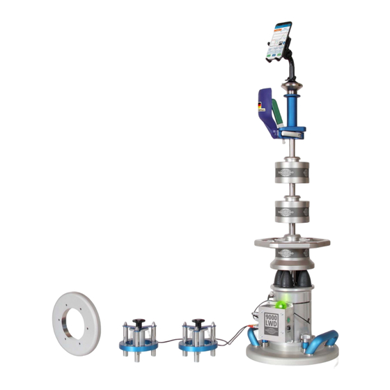
2.3 G ENERAL Smartphone‐holding device with support disc on guide rod Releasing device with eccentric clamp Two‐part guide rod Additional falling weights 5 kg (11 lbs) each (upon request) Falling weight 10 kg (22 lbs) with weight catching grip Vibration damper Load cell Central geophone Magic Eye Electronics of light weight deflectometer Connection sockets for external geophone OFF/ON button Loading socket for power pack Star screws for adjustment of plate diameter 300/150 mm Angled load plate handles External geophone (upon request) Load plate ring for diameter 200 mm (upon request) [10] ... -
Page 11: Specification
PECIFICATION 3.1 D EVICE ESIGNATION TERRATEST 9000 LWD 3.2 S ERIAL UMBER The serial number of the instrument consists of a four-digit number, attached in the form of a sticker to the cylinder of the central geophone. This sticker should never be removed or become unreadable. The serial number of external geophones and measuring instrument is identical. -
Page 12: Battery Power
3.6 B ATTERY OWER A long‐life Lithium Ion rechargeable battery type Sony US 18650 VTC 6 3.6 Volt, 3.12 Ah is installed in the device. The charging procedure takes ca. 4 to 5h depending on ambient temperature. Minimum ambient temperature amounts 0°C. For charging, only the power pack in the standard delivery must be used. The charging socket, labelled with „Charger 9V/max 2A“ is located below the START button. When switching ON the instrument, the charging state can be viewed by smartphone‐App „TERRATEST 9000 LWD“. A complete charge corresponds to 3.6 Volt, usually sufficient for 300 measurements, depending on ambient temperature, battery lifetime and other influences. ATTENTION Never attempt to open the battery. Improper handling or short circuit may give rise to fire hazard. Lithium is a highly reactive light metal, so that corresponding directives for transport and disposal must be observed. Also for this reason, the instrument or the battery itself should never be left to persons unaware of possible danger. According to the Directive on Waste Electrical and Electronical Equipment (2002/95/EG), the battery and electronic components should not be disposed of with domestic waste. This product must be handed over to collection points provided, responsible for electrical and electric equipment. In some countries manufacturers of similar electronic equipment are bound to take back electronic waste. Due to potentially hazardous substances contained, improper handling or treatment may entail negative impacts on environment and human health. Disposing of electronic parts in an appropriate manner also contributes to an effective use of natural resources. For more information, consult local authorities. TERRATEST LWD GmbH will take back electronic waste free of charge, and dispose of it in a safe and environmentally appropriate manner. [12] ... -
Page 13: Charging Procedure
3.7 C HARGING ROCEDURE Only the charging equipment supplied by the manufacturer should be used for charging. Plug the power cable into the socket labelled with „Charger 9V/max 1,25A“ of the electronics, which is located below the START button. The charging procedure takes ca. 4‐5h depending on ambient temperature. In the case of exhaustive discharge, the battery must be charged for ca. 18 hours. Maximum fluctuation in voltage must not exceed 10%. During the charging process, place the instrument in a dry room and take care that it is possible to disconnect the power pack from power at any time. Power Pack For that purpose, only the power pack (SYS1308‐1809‐W2E) with LEMO plug, approved by the manufacturer, should be used. The charging procedure on the basis of this power pack should be performed in dry indoor locations, at an ambient temperature >0°C. The inner pole is the positive (+) pole. Type: SYS1308‐1809‐W2E with LEMO plug Prim: 100‐240V AC, 47‐63Hz, 1A Class II Sec: 9V/2A IP20 The electronics must be switched OFF beforehand. Then insert the charging cable into the socket of the instrument, and finally connect the other end of the power pack to the mains. ATTENTION: When disconnecting the charging cable always grasp it from the plug. Pulling the cable itself may result in damage to the wires. The charging cable is equipped with a plug with LEMO „PUSHPULL“ lock and anti‐kink protection. To connect the cable, first open the hinged lid of the socket, and insert the plug carefully until stop. The plug automatically locks inside the socket, for detaching it must be unlocked. Grasp only from the plug itself, otherwise cable and socket may be damaged. ATTENTION: ... -
Page 14: Exchange Of Battery
3.8 E XCHANGE OF ATTERY Battery exchange is reserved to qualified personnel. The battery should only be replaced by the original model type Sony US 18650 VTC 6, 3.6 Volt, 3.12 Ah. Procedure: 1. The electronics must be switched OFF beforehand. 2. Use an Allen key 2.5 mm to detach the 4 hexagon socket screws of the case plate of the electronics by turning counterclockwise. 3. Carefully remove the cover plate of the electronics. The circumferential EMC gasket should not be damaged meanwhile. 4. Remove the battery and insert the new item (type Sony US 18650 VTC 6, 3.6 Volt, 3.12 Ah). Correct polarity must be observed! 5. Secure the battery by attaching a strip of hot glue. ATTENTION: Never attempt to open the battery. Improper handling or short circuit may give rise to fire hazard. ... -
Page 15: General Overview
ENERAL VERVIEW 4.1 I NTRODUCTION The „TERRATEST“‐ product family combines highly modern microelectronic components with the properties of an accurate ergonomic test instrument, which is extremely suitable for the use on construction sites. 4.2 I NNOVATIONS All „TERRATEST“‐ products have such outstanding, innovative features that they have become globally unique testing instruments for measuring bearing capacity: 4.2.1 Mechanical Innovations: Ergonomic, hexangular weight‐catching grip of the falling weight for comfortable handling Angled load plate handles as a coupling to the mobile transport system „CARRELLO“ Simple assembly/dismantling of the guide rod and the holding device for smartphone to ensure safe and space‐saving transport 4.2.2 Electronic Innovations: Data transfer via Bluetooth® Safe connection by valuable plugs and sockets User‐friendly, comfortable smartphone‐App to record measurements Magic Eye to visualize the control 4.3 D YNAMIC ... -
Page 16: Scope Of Application
surfaces, it is recommended to cover the soil with a thin layer of sand to fill gaps. Position the plate on the surface in horizontal orientation, as accurately as possible. In state of delivery, the central geophone is fixed by a cover screw, located centrally at the bottom of the load plate, to be removed by means of a coin or a flat screwdriver. Afterwards the tappet included in the delivery must firmly be bolted at that position. Before releasing the falling weight, the geophone must be centered again. For that purpose unlock the transport security, pull it up, put it down again and reinsert the lock of the transport security in lowest position. Verify the values stored in the smartphone‐App „TERRATEST 9000 LWD“, particularly with respect to the plate radius. Between the tests, contamination of the device must be removed to ensure accurate results. On very cohesive or moistened subsoil, perform measurement without making use of the tappet of the central geophone. To achieve this, fix the central geophone by means of the transport security in lowest position, and bolt the cover screw from below into the geophone. 4.4 S COPE OF PPLICATION The dynamic load plate test with light weight deflectometer is suitable for testing the bearing capacity and assessing the compaction quality of unbound or partially bound soil for earthworks and road construction. ‘Soil’ should be understood as including backfill materials, base courses without binders, soil improvements, cold recycling layers, mineral sealing layers, asphalt and not yet cured concrete. The testing method is especially suitable for coarse‐grained and mixed‐grained soils with a maximum grain size of 63 mm. 4.5 C ALIBRATION „TERRATEST 9000 LWD“ before delivery is calibrated acc. to manufacturer specification. During this procedure, all components are attuned specifically to one another. After completion, respective calibration tags with the expiry date are attached to the central geophone between transport security and electronics. A calibration certificate is provided as well. At least once per year, recalibration by TERRATEST LWD GmbH is required. Test results of a device that has not been calibrated or of a device with expired calibration date must not be used for evaluation of the bearing capacity of soil or rock. Prescribed calibration intervals therefore must be observed. 4.6 R ULES FOR ... -
Page 17: Assembly
ATTENTION Test results of a device that has not been calibrated or of a device with expired calibration date must not be used for evaluation of the bearing capacity of soil or rock. Prescribed calibration intervals must be observed. ATTENTION TERRATEST LWD GmbH shall not be liable for any damage, consequential damage or financial loss that occurs as a result of improper use and/or lack of professional knowledge when evaluating the test data. It is essential to ensure that the calibration is up to date and that the device is operated in accordance with the instructions of this document and local standards. ACHTUNG Always crosscheck with your domestic test method, to make sure that test results will be reliable. 4.7 A SSEMBLY For professional transport, the light weight deflectometer „TERRATEST 9000 LWD“ is shipped in dismantled state in transport box „VENEZIA“. Dimensions transport box „VENEZIA“: 800 x 400 x 350 mm / 31.2‘‘ x 23.6‘‘ x 40.25‘‘ Weight transport box „VENEZIA“: Weight empty 19 kg / 41,8 lbs Total weight 58 kg / 127,6 lbs incl. complete set of accessories The delivery contains a 17 mm spanner as well as Allen keys 6mm, 5 mm and 2.5 mm. [17] ... - Page 18 Assembly procedure: 1. Screw the first guide rod part (the element without scale) into the adapter in the center of the load cell, located between the vibration dampers. 2. Now introduce the bore of the falling weight into the lower guide rod. Place the 10 kg (22 lbs)‐ falling weight onto the rubber vibration dampers. 3. Bolt the second guide rod (the item with scale) from above into the first guide rod from above. The screw connection must be tight. 4. Slide the bore of the releasing device (with the blue handle pointing upward) ...
- Page 19 7. Firmly bolt the disk for the smartphone holding device onto the upper end of the guide rod. 8. Fix the smartphone holding device on the disk by means of the suction foot, by pressing down the small lever in the front of the holder. 9. For measurements to be carried out with tappet and not with geophone fixed, install the tappet beforehand. In state of delivery, the central geophone is fixed by a cover screw, located centrally at the bottom of the load plate, and to be removed by means of a coin or a flat screwdriver. Afterwards firmly bolt the tappet included in the delivery at that position. [19] ...
-
Page 20: Load Plate Diameter
4.7.1 Load Plate Diameter In state of delivery, the load plate „DUO‐SWITCH“ is mounted to the light weight deflectometer „TERRATEST 9000 LWD“, which allows easy exchange between diameters of 300 mm (11,8‘‘) and 150 mm (5,9“). The default configuration is 300 mm (11,8‘‘). 4.7.1.1 Diameter of Load Plate 100 mm (3,9‘‘) For diameter 100 mm, first detach the installed „DUO‐SWITCH“ load plate from the cylinder of the central geophones as follows: 1. Unscrew the six hexagon socket head screws M6x20 from the dark‐gray retaining ring at the bottom of the load plate. 2. Remove this retaining ring. 3. Detach the six hexagon socket head screws M6x20, which become visible when the ring has been removed. 4. Place the load plate on a stable ground. 5. Loosen the three star grips at the top of the load plate by turning them counterclockwise. 6. Lift off the cylinder of the central geophone from the load plate. Without the „DUO‐SWITCH“ element, the diameter of the load plate finally amounts to 100 mm (3,9‘‘). 4.7.1.2 Diameter of Load Plate 150 mm (5,9‘‘) The mounted load plate „DUO‐SWITCH“ consists of an inner and an outer ring, guided in a mobile manner. When diameter 150 mm is desired, first the three star grips at the top of the load plate must be loosened by turning them counterclockwise. Rotate the outer part of the load plate, until the mark of the inner ring matches the 150 mm – mark at the outer ring. The outer ring from now on is in contact with the rest of the assembly only in a mobile manner, and the load plate in this setting disposes of a diameter of 150 mm (5,9‘‘). [20] ... - Page 21 4.7.1.3 Diameter of Load Plate 200 mm (7,9‘‘) (optional) Proceed as described in chapter 4.7.1.1 „Diameter of Load Plate 100 mm (3,9‘‘)“ . Now press the round recess of the 200 mm load plate from below onto the 100 mm load plate. Fix the 200 mm load plate by means of six hexagon socket head screws M6x20. During this procedure it is important that the arched face of the 200 mm ring represents the upper and its even face the bottom side (supporting surface) of the load plate. After assembly, the diameter of the load plate amounts to 200 mm (7,9‘‘). 4.7.1.4 Diameter of Load Plate 300 mm (11,8‘‘) In default, the diameter of the load plate of the light weight deflectometer „TERRATEST 9000 LWD“ amounts to 300 mm. The mounted load plate „DUO‐SWITCH“ consists of an inner and an outer ring, guided in a mobile manner. When support diameter 300 mm diameter is desired, the mark of the inner ring must match the 300 mm – mark at the outer ring. To achieve this, lift the falling weight and rotate the outer ring. Then place back the load plate onto level ground, and fix the three catches on the upper face of the load plate by pressing down and turning the star grips clockwise. From now on, the diameter of the load plate amounts to 300 mm (11,8‘‘). [21] ...
-
Page 22: Mass Of Falling Weight
4.7.2 Mass of Falling Weight The mass of the falling weight with the hexagonal weight catching grip amounts to 10 kg (22 lbs). To increase the mass to 15 kg (33 lbs) or 20 kg (44 lbs), two additional falling weights with a mass of 5 kg (5 lbs) can be ordered. 4.7.2.1 Increasing the Mass to 15 kg (33 lbs) Remove the three plastic caps from the bores at the upper face of the 10 kg falling weight. Place the additional 5 kg weight onto the 10 kg falling weight from above, and screw the three hexagon socket head screws M8x70 of the additional 5 kg weight into the bores of the 10 kg falling weight. From now on, the mass of the assembly amounts to 15 kg (33 lbs). 4.7.2.2 Increasing the Mass to 20 kg (44 lbs) Proceed as described in chapter 4.7.2.1, and attach also the second additional 5 kg weight by placing it onto the first installed item, mutually connecting them by inserting the three hexagon socket head screws M8x70 of the second into the bores of the first 5 kg weight (located below). Tighten the connection. The complete mass achieved amounts to 20 kg (44 lbs). [22] ... -
Page 23: Connection Of The External Geophones, Optionally Available
4.7.3 Connection of the external geophones, optionally available Two additional geophones can be ordered. Each of them is mounted inside an own holding frame, which is marked by number 1 or 2 inside the retaining ring. A separate type plate for each of these geophones is attached as well, featuring the four digit number of the light weight deflectometer itself, followed by ‘/G1’ or ‘/G2’. Both of them are equipped with LEMO push‐pull plugs for easy connection to the electronics of the light weight deflectometer. For quick distinction, colored anti‐kink protection is provided (yellow for item 1, red for item 2). To connect the external geophones, carefully insert their plugs into the socket of identical color. For disconnection, push‐pull connections are provided, only opening when pulling from the plug housing. ATTENTION: When disconnecting the cable always grasp it from the plug. Pulling the cable itself may result in damage to the push‐pull connection. As soon as the external geophones are connected and their distances to the middle of the central geophone adjusted, they have to be detached from their holding frames at the top side. To achieve this, hold the geophone with one hand, and rotate the upper black star grip counterclockwise with the other hand. The external geophone is now centered by three springs and can be placed carefully onto the testing surface. ATTENTION: For transport, reinstallation of the external geophones to their holding frames is imperative. For that purpose, lift the external geophone with one hand, so that the screw of the star grip fits to the boring of its case lid. With the other hand, tighten the star grip rotating clockwise. [23] ... -
Page 24: Vibration Dampers
4.7.4 Vibration Dampers In state of delivery, four vibration dampers are installed. Their number can be reduced to three, in order to modify force transmission. For that purpose, first detach all of them from the cylinder of the central geophone, by turning them counterclockwise. Besides the bores for four‐damper‐ configuration and the guide rod in the center, two further borings are provided enabling an equidistant installation of three dampers in the form of a triangle. Attach the dampers correspondingly. [24] ... -
Page 25: Dismantling
4.8 D ISMANTLING The dismantling procedure has to be carried out top down. 1. Start with the smartphone holding device by pulling up the small black lever and then drawing off the suction foot. 2. Unscrew the disk of the smartphone holding device from the upper end of the guide rod by rotating it counterclockwise. 3. Loosen the lever of the eccentric clamp and remove the releasing device from the guide rod by drawing it upward. 4. Draw the falling weight upward to separate it from the guide rod. 5. Reinstall the catch device on the guide rod and fix it by means of the eccentric clamp in the upper sector of the two‐part guide rod. 6. Use the lever effect of the catch device and unscrew the complete two‐part guide rod by rotating it counterclockwise. 7. Hold the upper part of the two‐part guide rod at the catch device. Use the 17 mm spanner to separate the lower part (grasp at the lower end) from the upper part, to dismantle the two‐part guide rod. 8. Unscrew the tappet (if installed) of the central geophone and reinstall the cover plate. 9. All components have to be stored in transport box „VENEZIA“. [25] ... -
Page 26: Measurement With „Terratest 9000 Lwd
„TERRATEST 9000 LWD“ EASUREMENT WITH 5.1 P REPARING THE ESTING OINT Place the load plate on the ground, ensuring full and even contact. Create a smooth and level surface on the area to be inspected, by moving the plate back and forth, or by means of auxiliary equipment, e.g. a trowel. Loose material (like stones) has to be removed. In the case of soil irregularities, spread a thin layer of fine‐grain quartz sand on the surface. The sand is only intended to compensate for unevenness. Full and even contact is imperative. Attach the smartphone to its holding device. 5.2 T EST XECUTION Start App „TERRATEST 9000 LWD“ on the smartphone (refer to section 6.1, page 29). Switch ON the electronics by pressing green „Start“‐button at the housing. The instrument first performs a self‐ test, to be recognized by the rapidly changing color of the control lamp of the „Magic Eye“. After completion, the color of the „Magic Eye“ changes to red. The Bluetooth connection to the smartphone can be established as follows: In the smartphone app, press the red Bluetooth symbol with white background appearing in the lower left corner of the application, and in the displayed list select device „LWD9000“. When the connection is established, the color of the Bluetooth symbol background changes to Green, and the color of the „Magic Eye“ to Blue. The desired falling height can be adjusted now. Loosen the eccentric clamp of the releasing device, select the height by displacing it and fix this position by stretching the clamp. To center the geophone again, draw off the transport security from the load ... - Page 27 fall. After impact the color of the control lamp of the „Magic Eye“ changes to Blue. Recorded data are transferred to the smartphone. When these data are successfully received and processed by the app, the buzzer sounds again, and the values are displayed on the smartphone. The smartphone‐App „TERRATEST 9000 LWD“ is described in detail in chapter 6, page 29ff. Between the tests, contamination of the device must be removed to ensure accurate results. On very cohesive or moistened subsoil, preferably perform measurement without making use of the tappet of the central geophone. To achieve this, the tappet can be fixed by engaging the transport security in upper position and attaching the cover. ATTENTION Damages issuing from improper handling may invalidate the warranty. ATTENTION During the entire test procedure, firmly hold the upper grip with one hand the upper. The device should never be left unattended with the weight engaged in upper position, as the system in this state is not stable and may tip over, giving rise to damage or injuries. Do not engage the falling weight in upper position before the test is immediately intended to be carried out. Persons not involved with the test procedure should not remain in direct vicinity. After impact, place the falling weight at the bottom onto the vibration dampers. [27] ...
-
Page 28: Magic Eye
5.3 „M “ AGIC The Bluetooth®‐transmission unit of the measuring electronics features a „Magic Eye“ (transparent hemispherical cover over the transmitter), which can appear in five different colors. 5.3.1 „Magic Eye“ RED After switching ON the measuring electronics by pressing the green button, the system first performs a self‐test for a second, which can be recognized by the rapidly changing color of the control lamp of the „Magic Eye“. After completion, the electronics for a second signals the charging state of the Lithium ion battery by means of a white or yellow diode. White: Charging state above 20% of full capacity, yellow: Below that limit. Afterwards, the color of the „Magic Eye“ changes to red, showing that the electronics are ready for operation. In this state, the Bluetooth®‐transmission unit of the measuring electronics waits for establishment of the connection to the smartphone app. If in the course of the measurement, the color of the „Magic Eye“ changes to Red again, the connection between measuring electronics and smartphone is obviously interrupted. Their mutual distance meanwhile may be too large. The measurement is cancelled. Reduce this distance, and establish the mutual connection again. When the problem is solved, the voice output of the smartphone communicates „CONNECTED“. 5.3.2 „Magic Eye“ BLUE As soon as the Bluetooth®‐ connection between smartphone‐App and measuring electronics is established, the „Magic Eye“ is illuminated in Blue. 5.3.3 „Magic Eye“ GREEN Green color of the „Magic Eye“ shows that both measuring electronics and smartphone‐App are ready for measurement. At the end of the measurement, the color of the „Magic Eye“ returns to Blue which symbolizes the existing Bluetooth®‐connection. [28] ... -
Page 29: Smartphone -App „Terratest 9000 Lwd
‐A „TERRATEST 9000 LWD“ MARTPHONE PP 6.1 I NSTALLATION 6.1.1 System Requirements Smartphone‐App „TERRATEST 9000 LWD“ can be installed on all usual smartphones with Bluetooth interface, as well as the Android operating system from version 5.1 (Lollipop) or Apple from version 10 and is only used with light weight deflectometer „TERRATEST 9000 LWD“. To determine the position, GPS equipment must be implemented. 6.1.2 Installation of „TERRATEST 9000 LWD“ App On the smartphone, start the „Google Play Store“or Apple "App Store". In the search line of the Store, enter „TERRATEST“, and select App „TERRATEST 9000 LWD“ for installation. Then follow the instructions appearing on the display. [29] ... - Page 30 6.2 O PERATING LEMENTS OF PP „TERRATEST 9000 LWD“ The user interface is subdivided into three zones. Upper zone: Buttons for Settings Menu (replaced by Back button in the corresponding submenus) Information bar Charging indicator for battery (only shown when device is connected) Time, date and weather information (latter element only shown when Internet connected) Central zone: Buttons for Project settings Test settings GPS coordinates Green button to enable/disable recording of GPS coordinates Lower zone: ...
-
Page 31: Settings
6.3 S ETTINGS Settings can be viewed from start page of App by settings menu, as well as by swiping from the left screen border to the center on all pages. [31] ... -
Page 32: User Profile
6.3.1 User Profile This submenu is intended for contact data of the company including a logo. This information is required for correct documentation (measurement logs and header). Simple one‐finger‐tapping into the desired line calls up a keyboard for entry of text. After completion, press „Save“ button located below the entry fields. When correction is required, one‐finger tapping into the desired line and overwriting of current information is enough. Do not forget to press „Save“ in the end. Correct completion of storage procedure is visualized by „user profile saved successfully“ message. Below the lines for company information, the „Delete Profile“ button and selection buttons for metric/imperial units can be found. Note that pressing “Delete Profile“ deletes all user data entered beforehand. Change between metric and imperial units can be performed anytime. All settings enter into force by pressing „Save“ button. [32] ... -
Page 33: Project Settings
6.3.2 Project Settings Project settings can be invoked from start page of App by settings menu, as well as on all pages by swiping from the left screen border to the center and pressing „Project Settings“ button. The overview page of this menu features buttons for submenus for „Site Settings“, „Job Settings“, „Location Settings“ and furthermore a „Drop List“, if measurements already have been carried out. If settings have been implemented beforehand, active settings are displayed below the buttons together with their names, just for information. Project settings appear in a hierarchical structure, similar to the folder structure on a computer. The upper directory relates to the site, in which the jobs are stored. The job folder (which must be opened beforehand) is intended for the locations. The measurements (drops) finally are saved in the location folder. Site1 Site2 Job1 Job2 Location1 Drop1 Job3 Location1 Drop2 Drop3 Drop4 [33] ... - Page 34 6.3.2.1 Site Settings Tapping on button „Site Settings“ grants access to the overview page for stored sites. Each site appears in an own line. By clicking on the checkbox in the upper line, it is possible to activate all sites simultaneously. This is followed by the title „Site Name“, and consecutively export and trash can icon. Each line of the sites starts with the selection field. By clicking on the checkbox, the corresponding site can be marked for export or erasing. The checkbox is followed by the name of the site and the pencil icon. After the selection of a site, its font color changes to Red. From now on, all further activities relate to this site and are stored with it together. Site information can be changed by tapping on the pencil icon. Pressing „Cancel“ button invalidates, „Save“ button stores these modifications. [34] ...
- Page 35 A new site can be created by pressing „+ Site“‐ button located at the right side of the “Start Test“‐ Button. This generates a new form page, in which all information for the site can be entered. At least one name must be specified for this site. Pressing „Cancel“ button invalidates the entry, and the new site is not created. „Save“ button stores the entry. The new site automatically becomes the active site under which the following new created jobs and locations as well as the following measurements (drops) are stored. It is possible to select a single, a group or all sites for further activities. Tapping on a particular checkbox and trash can icon, the corresponding site after confirmation prompt is erased, together with all jobs, locations and drops stored beforehand. Tapping on a particular checkbox and export symbol marks the selected site for export together with all of its jobs, locations and drops. A selection window is displayed, in which the user may decide to prepare data for export as PDF‐ report, as TC9 ‐ file for further evaluation by software package „TERRATEST LWD“ or as CSV – for further processing e.g. by Microsoft Excel. After selection of the desired export format and confirmation by „YES“ button, a menu opens in order to choose the e‐mail‐program. Select the desired e‐mail‐program, specify the receiver and enter other information (if required). For creation of export data and e‐mail‐transmission of course a data connection must exist. [35] ...
- Page 36 6.3.2.2 Job Settings The information bar displayed when button „Job Settings“ is pressed, contains the name of the currently active site. An overview page for stored jobs appears as well. Each of the stored jobs is shown in an own line. In the upper line, it is possible to select all jobs simultaneously by clicking on the check box. This is followed by the title „Job Name“, and consecutively export and trash can icon. Each line of the jobs starts with the selection field. By clicking on the checkbox, the corresponding job can be marked for export or erasing. The checkbox is followed by the name of the site under which it was stored and the pencil icon. After the selection of a job, its font color changes to Red. From now on, all further activities relate to this job and are stored with it together. Job information can be changed by tapping on the pencil icon. Pressing „Cancel“ button invalidates, „Save“ button stores these modifications. [36] ...
- Page 37 A new job can be created by pressing „+ Job“‐ button located at the right side of the “Start Test“‐Button. This generates a new form page, in which all information for the job can be entered. At least one name must be specified for this job. Pressing „Cancel“ button invalidates the entry, and the new job is not created. „Save“ button stores the entry. The new job automatically becomes the active job under which the following new created locations as well as the following measurements (drops) are stored. It is possible to select a single, a group or all jobs for further activities. Tapping on a particular checkbox and trash can icon, the corresponding job after confirmation prompt is erased, together with all locations and drops stored beforehand. Tapping on a particular checkbox and export symbol marks the selected job for export together with all of its locations and drops. A selection window is displayed, in which the user may decide to prepare data for export as PDF‐ report, as TC9 ‐ file for further evaluation by software package „TERRATEST LWD“ or as CSV – for further processing e.g. by Microsoft Excel. After selection of the desired export format and confirmation by „YES“ button, a menu opens in order to choose the e‐mail‐program. Select the desired e‐mail‐program, specify the receiver and enter other information (if required). For creation of export data and e‐mail‐transmission of course a data connection must exist. [37] ...
- Page 38 6.3.2.3 Location Settings The information bar displayed when button „Location Settings“ is pressed, contains the name of the currently active site together with the currently active job, and it appears an overview page for stored locations of the active job of the active site. Each of the stored locations is shown in an own line. In the upper line, it is possible to select all locations simultaneously. This is followed by the title „Location“, and consecutively export and trash can icon. Each line of the locations starts with the selection field. By clicking on the checkbox, the corresponding location can be marked for further use. The checkbox is followed by the name of the location and the pencil icon. After the selection of a location, its font color changes to Red. From now on, all further activities relate to this location and are stored with it together. Location information can be changed by tapping on the pencil icon. Pressing „Cancel“ button invalidates, „Save“ button stores these modifications. [38] ...
- Page 39 A new location can be created by pressing „+ Location“‐ button located at the right side of the “Start Test“‐Button. This generates a new form page, in which all information for the location can be entered. At least one name must be specified for this location. When implementing a location, the corresponding GPS coordinates are displayed in a separate line. By pressing update button, these coordinates can be modified when changing the position. If a photograph of the location for the following measurements is desired, tap on the camera symbol in ‘Picture’ line. Pressing „Cancel“ button invalidates the entry, and the new location is not created. „Save“ button stores the entry. The new location automatically becomes the active location under which the following measurements (drops) are stored. It is possible to select a single, a group or all locations for further activities. Tapping on a particular checkbox and trash can icon, the corresponding location after confirmation prompt is erased, together with all drops stored beforehand. Tapping on a particular checkbox and export symbol marks the selected location for export together with all of its drops. A selection window is displayed, in which the user may decide to prepare data for export as PDF‐ report, as TC9 ‐ file for further evaluation by software package „TERRATEST LWD“ or as CSV – for further processing e.g. by Microsoft Excel. After selection of the desired export format and confirmation by „YES“ button, a menu opens in order to choose the e‐mail‐program. Select the desired e‐mail‐program, specify the receiver and enter other information (if required). For creation of export data and e‐mail‐transmission of course a data connection must exist. [39] ...
- Page 40 6.3.2.4 Drop List The button “Drop List” only appears, if measurements for the corresponding site, job und location already have been stored beforehand. The information bar displayed when button „Drop List“ is pressed, contains the name of the currently active site together with the currently active job and location. Below an overview page for stored measurements (drops) to these project sub‐items appears as well. This overview can also be opened in the course of a measurement, by tapping on the gearwheel icon and selecting ‘Drop List’ in the displayed Quick Menu. In the information bar, site, job and location are available in form of buttons, so that the user can change over to a drop overview for other sites, jobs and/or locations whenever needed. For that purpose, a selection window is opened, to choose the desired overview. Each of the stored drops is shown in an own line. In the upper line, it is possible to select all drops simultaneously by a click on the checkbox. This is followed by the title „Drop Name“, and consecutively export and trash can icons well as a Shift symbol. Each line of the drops starts with the selection field for further use of the corresponding drop. The checkbox is followed by date and time at which the measurement took place, as well by the pencil icon. A click on the pencil icon beside the drop name enables the measuring results to be viewed. An overview window is displayed informing the user about plate diameter used, measurement number, date and time, curves of impact and settlement, as well as the results. After tapping on the plate diameter, this parameter can be changed and stored even afterwards. On the basis of this new diameter, all results are recalculated and the results display correspondingly adapted. Previous and subsequent measurements are accessible by means of the left/right arrow keys provided above the diagrams. Close the view by Quit button. It is possible to select a single, a group or all jobs for further activities. [40] ...
- Page 41 Tapping on a particular checkbox and trash can icon, the corresponding drop after confirmation prompt is erased. Tapping on a particular checkbox and export symbol marks the selected drop for export. A selection window is displayed, in which the user may decide to prepare data for export as PDF‐ report, as TC9 ‐ file for further evaluation by software package „TERRATEST LWD“ or as CSV – for further processing e.g. by Microsoft Excel. After selection of the desired export format and confirmation by „YES“ button, a menu opens in order to choose the e‐mail‐program. Select the desired e‐ mail‐program, specify the receiver and enter other information (if required). For creation of export data and e‐mail‐transmission of course a data connection must exist. A click on the desired selection field and on the Shift symbol opens a window, which requests for selection of site, job and/or location. Pressing „Move“ button shifts the selected drop (after confirmation prompt) to the desired site/job/location. The procedure may be interrupted by „Cancel“. [41] ...
- Page 42 Export Delete Move [42] ...
-
Page 43: Device Settings (Drop Settings)
6.3.3 Device Settings (Drop Settings) Drop settings can be invoked from start page of the App, as well as on all pages by swiping from the left screen border to the center and pressing „Drop Settings“ button. This overview can also be opened in the course of a measurement, by tapping on the gearwheel icon and selecting ‘Drop Settings’ in the displayed Quick Menu. „Drop Settings“ button displays an overview page for the device settings currently used, also for calculation of measuring results. The currently selected plate diameter appears with red background. Selecting a particular diameter stores that parameter for the drops. Below the line for the plate diameter, values for Poisson’s Ratio (Standard 0.5), Distribution Factor (Standard 2.0), as well as the distance of the optionally available external geophones to the central geophone (in mm) can be entered. An entry of zero indicates that no external geophones are used. Pressing „Cancel“ button invalidates the entry, and the current values are not modified. „Save“ button stores the entry. [43] ... -
Page 44: Measurement
6.4 M EASUREMENT 6.4.1 Establishment of Connection Switch ON the measuring electronics by pressing the green button at the housing of the electronics. The system first performs a self‐test for a second, which can be recognized by the rapidly changing color of the control lamp of the „Magic Eye“. After completion, the electronics for a second signals the charging state of the Lithium ion battery by means of a white or yellow diode. White: Charging state above 20% of full capacity, yellow: Below that limit. Afterwards, the color of the diodes changes to Red. The Bluetooth connection to the smartphone can be established now. In the smartphone app, press the red Bluetooth symbol with white background appearing in the lower left corner of the application, and in the displayed list select device „LWD9000“.If voice output in the smartphone app has been activated, the system communicates: „Connecting“. When the connection is successfully established, the color of the „Magic Eye“ is illuminated in Blue, and the Bluetooth button of the smartphone app appears with a green background. The voice output communicates: „Connected“. [44] ... -
Page 45: Measurement
6.4.2 Measurement When the connection has been implemented, adjust the falling height at the guide rod, as described in chapter 5.2 „Test Execution“, page 26 .For that purpose, center the central geophone again by detaching the transport security from the load cell. Pull up the transport security and let it fall. Afterwards this transport security must be reattached in the lowest position by pressing it in. Verify the values stored in the smartphone‐App „TERRATEST 9000 LWD“, particularly with respect to the plate radius (chapter 6.3.3 “Device settings”, page 43). The recording of measuring results is started by pressing „Start Test“ button. The system displays an empty form page to present the results. The upper information bar contains the names of the active „Site“, „Job“ and „Location“, under which the following measurements are intended to be stored. The plate diameter set for this measurement is shown at the left side above the diagram and can be changed afterwards by pressing “Plate Diameter” button. ... - Page 46 At the right side at the top of the diagram, a gearwheel symbol is shown, granting access to a Quick menu for device settings or to the Drop List. In the right lower corner, a photograph of the location is illustrated, if recorded beforehand, and a camera symbol. Pressing the camera symbol enables the photograph to be updated in case of need. Now with one hand draw the falling weight upward and engage it in the releasing device, by pulling and releasing the green lever with the other hand. The falling weight is suspended in upper position. The measurement is initiated by pressing “Ready” button. The color of this button changes from Green to Red, and the buzzer on the smartphone activates. The control lamp of the „Magic Eye“ of the device is illuminated in Green, which shows that the system is ready to measure. Pull the green lever of the releasing device, and let the falling weight fall down onto the vibration dampers in free fall. After impact the color of the control lamp changes to Blue. Recorded data are transferred to the smartphone. [46] ...
-
Page 47: Transmission Of Measuring Data
When these data are successfully received and processed by the app, the buzzer sounds again, and the values are displayed on the smartphone. For further measurements, fix the falling weight again in the releasing device, press “Ready” button in the smartphone, and let the falling weight fall down again. This procedure is repeated until the measuring sequence is complete. In the end, press „Quit“ button. The application leaves the measuring mode and returns to the overview page of the smartphone‐App. 1 – Time history of the force impulse applied to the load plate 2 – Time history of the deflections measured with the central geophone G0 and the external geophones G1 and G2 3 – Maximum value of the force 1 pulse 4 – Distance between the central geophone G0 and the 5 external geophones G1 and G2 5 – Pressure below the load 3 plate 6 – Maximum deflections measured by the geophones G0 / G1 / G2 7 – Peake widht of the force ... -
Page 48: Warranty
ARRANTY TERRATEST LWD GmbH provides a warranty for this device of one year from delivery. This 1‐year warranty granted in addition to statutory provisions is subject to the following warranty conditions. Statutory warranty claims shall not be affected by these warranty claims. If manufacturing or material defect occurs within the warranty period, the device will be repaired or replaced at the expense of TERRATEST LWD GmbH. Any warranty claim presupposes of sufficient proof, e.g. an accurate invoice. The warranty claim must be raised within the warranty period. The warranty does not cover devices or device parts which are exposed to normal wear and must be considered as wear parts. The warranty will be void, if the device should be damaged and/or not be used appropriately (for example if the instructions provided in this manual are not followed). Repairs may be carried out only by TERRATEST LWD GmbH or repair shops authorized by TERRATEST LWD GmbH. All instructions mentioned in this manual must be strictly observed for proper use of the device. Strictly avoid any utilization of device and any way of operating that this instruction manual advises or warns against. 1. Scope of Warranty 1.1. With this warranty declaration, TERRATEST LWD GmbH certain rights to the purchaser, restricted by kind and content (see „Exclusions“ and „Limitations“ in section 2). Please read this document carefully. By exercising any rights derived from the warranty you declare concurrently that you have understood and accepted their conditions. Your statutory provisions (warranty) against the party from which you have directly acquired this product persist irrespective of and in addition to this warranty and will not be affected by it. 1.2. TERRATEST LWD GmbH warrants that under normal circumstances every ‘System’ (see below) which is sold for the first time by TERRATEST LWD GmbH or an authorized dealer in a country of the European Union or Switzerland (our trading area) will be free of defects in material or workmanship for the duration noted in the warranty card supplied with the system. ‘System’ refers to our brand‐ new product, including all original parts and components (provided that these were offered as potions and/or accessories and installed at the time of purchase). 1.3. Software supplied with the system does not fall within the scope of this warranty. TERRATEST LWD GmbH does not warrant that the software will work faultlessly or without disruptions and neither that it will fulfill your requirements. 1.4. In case of warranty, TERRATEST LWD GmbH will, at reasonable discretion, repair or replace faulty system or parts covered by this warranty by new or as good as new parts or systems. In cases where TERRATEST LWD GmbH uses parts or systems that are as new, these will be original TERRATEST LWD GmbH products that underwent a general overhaul, so that their characteristics and performance equals brand‐new products. All parts and systems replaced under the terms of this limited warranty become property of TERRATEST LWD GmbH. ... - Page 49 2. Exclusions and Limitations This warranty is subject to the following exceptions and limitations: 2.1. Exclusions This limited warranty does not cover: 2.1.1. Products, which were not manufactured by TERRATEST LWD GmbH or which were originally sold to an end user outside the area in which this warranty applies. 2.1.2. Products, which were damaged or rendered inoperable by one of the following ways of utilization or operating: 2.1.2.1. Any use of the product for purposes other than intended, including but not limited to non‐ compliance with the instruction manual supplied with the system, or other forms of improper use or neglect of the system; 2.1.2.2. Any modification of the system, for instance the use or mounting of components which were not manufactured and/or sold by TERRATEST LWD GmbH ; 2.1.2.3. Any service or repair carried out by non‐authorized third parties, i.e. not TERRATEST LWD GmbH; 2.1.2.4. Improper transport or packaging when returning the system to TERRATEST LWD GmbH. 2.1.3. Loss or damage of programs or storage media (except in case of producer’s liability, according to the product liability legislation which will be applied as appropriate to the damage suffered). You are responsible for a backup of al programs, data and/or media. As mentioned above, TERRATEST LWD GmbH reserves the right to replace any system sent in for repair with new or overhauled products of comparable quality and performance, in which case all data saved on the original system may become permanently inaccessible. 2.1.4. Consumables, i.e. any parts which need to be replaced regularly under normal conditions of use. 2.1.5. Minor defects on LC‐Displays that occur in devices which are equipped LC display technology. 2.2. Limitations and exclusions of warranty 2.2.1. No rights other than those explicitly granted herein can be derived from this warranty. This applies in particular to all other warranties, whether expressed, implied, or statutory, for which TERRATEST LWD GmbH disclaims any liability. These include, among others, any implied warranties of marketability or fitness for a particular purpose. Any compulsory official warranty deriving from the applicable law is limited by the conditions of this warranty. 2.2.2. In no case shall TERRATEST LWD GmbH be liable for damages caused by coincidence, for consequential damages caused by a defect, or for loss or profit, employment opportunities, data or use, irrespective of whether such claims are based on contractual entitlements, assurances concerning the utilization or performance of the system, or the use of the device in any way prohibited by law or advised against in this documentation, or whether such claims concern the software supplied by TERRATEST LWD GmbH, regardless of whether it was pre‐installed or enclosed with the product. This exclusion of liability applies even if TERRATEST LWD GmbH has been informed about the possibility of such damages. ...
- Page 50 2.2.3. The limitations and exclusions of liability mentioned in section 2.2.2. do not apply, if the suffered loss or damage is the direct result of an arbitrary deception or a violation of a legal obligation by TERRATEST LWD GmbH provided that TERRATEST LWD GmbH has acted with gross negligence. Neither do they apply if their exertion should restrict a valid entitlement against TERRATEST LWD GmbH under the product liability legislation, which applies respectively to the damages suffered by the end user. 2.3. If you make a claim under this warranty, you acknowledge concurrently that no other entitlements against TERRATEST LWD GmbH regarding the purchase or use of your system exists other than those warranty and compensation benefits described above. 2.4. All entitlements based on this warranty become time‐barred, if they are not claimed within one year after emergence. 3. Obtaining warranty service Please contact TERRATEST LWD GmbH to obtain warranty service, or should you have any cause for complaint. TERRATEST LWD GmbH Dianastrasse 4 16515 Oranienburg Germany Tel: +49 152 02554404 www.terratest‐lwd.com info@terratest‐lwd.com [50] ...
- Page 51 8 EC‐D ECLARATION OF ONFORMITY In accordance with the EC Low voltage directive, 2006/95/EG acc. to annex III B; of 12 December 2006 We hereby declare that the below mentioned product complies with the fundamental health and safety regulations of the EC Low Voltage Directive, by virtue of its design and construction, as well as its configuration, which was placed on the market by us. This declaration shall become null and void should any alterations be made to the product without our prior agreement. Manufacturer/Representative: TERRATEST LWD GmbH Dianastrasse 4 16515 Oranienburg / Berlin GERMANY of Light weight deflectometer Description of electrical equipment: Function: Test instrument to determine bearing capacity of the soil Type/Model: TERRATEST 9000 LWD Serial Number: 09xx Year of construction: 2019 We furthermore declare the compliance with the following directives / regulations, which apply to the product: ‐ EC‐Low Voltage Directive 2006/95/EG ‐ EMC‐Directive (2004/108/EG) ‐ Degrees of protection provided with the enclosures (IP53) ‐ acc. to VDE 0470 part 1 (DIN EN 60529 edition 09/2015) ‐ RoHS‐Directive 2002/95/EG ‐ WEEE‐Directive 2002/96/EG Applied harmonized standards, in particular: Other applied technical standards and specifications: ‐ EN ISO 12100‐1:2003 Safety of machinery – Basic concepts, general principles for design ‐ Part 1: Basic terminology, methodology ...
Need help?
Do you have a question about the 9000 LWD and is the answer not in the manual?
Questions and answers
How do i calibrate the coordinates on the terra test its 500mm off accuracy
The provided context does not contain specific instructions on calibrating the coordinates on the TERRATEST 9000 LWD. However, it mentions that the device must be calibrated according to the manufacturer's specifications before delivery and requires recalibration at least once per year by TERRATEST LWD GmbH. It also notes that uncalibrated devices or those with expired calibration must not be used for evaluating soil or rock bearing capacity. For precise coordinate calibration, refer to the device settings in the smartphone app or the manufacturer’s guidelines.
This answer is automatically generated