Table of Contents
Advertisement
Quick Links
Advertisement
Table of Contents

Subscribe to Our Youtube Channel
Related Manuals for TERRATEST 5000 BLU


Summary of Contents for TERRATEST 5000 BLU
- Page 1 Instruction Manual ‘TERRATEST 4000 USB’ ‘TERRATEST 5000 BLU’ Made in Germany...
- Page 3 Phone.: +49 3301 700 700 · Fax: + 49 3301 55 44 0 www.terratest.de · info@terratest.de TERRATEST GmbH ensures constant improvement and development of its products and hence reserves the right to make changes to its products at any time, and without prior notice.
-
Page 4: Table Of Contents
Changing the Paper ........36 Test Execution ‘TERRATEST 5000 BLU’ ......38 Preparing the Testing Point . - Page 5 ‘TERRATEST 2.0’ Software ........
-
Page 6: Documentation
TERRATEST GmbH cannot be held liable for errors contained in this documentation, or for accidental or sequential damage in connection with the delivery, performance, or use of the material. -
Page 7: General Safety Information
CAUTION Never place or charge the testing computer or load plate of ‘TERRATEST 5000 BLU’ in areas with excessive humidity, high temperatures, direct sunlight, or close to open flames. Doing so carries the risk of fire or electric shock. -
Page 8: Safety Precautions During Power Supply
(-) pole of the battery. The cable contains a 2A/32V fuse. Only the permanently-installed, long-lasting, rechargeable battery pack approved by the manufacturer (type 8904 7.4 V/2.4 Ah) should be used in the Bluetooth sensor dome (‘TERRATEST 5000 BLU’ ONLY). ® This battery pack should only be replaced by the manufacturer. -
Page 9: Safety Precautions During Operation
If it rains, cover and protect testing computer and load plate of ‘TERRATEST 5000 BLU’. ATTENTION Protect the testing computer and load plate of ‘TERRATEST 5000 BLU’ from water, liquids, and any flammable substances. There is a risk of fire if flammable liquids enter the device and make contact with the electric components. -
Page 10: Packaging
Please also advise TERRATEST GmbH of the damage and the name of the carrier, so that we can also get in contact with the transport company. -
Page 12: Contents Of Delivery
2. Contents of Delivery 2.1 Basic Package ‘TERRATEST 4000 USB’ Light Weight Deflectometer 10 kg corresponding to German standard TP BF-StB Part B 8.3 ‘TERRATEST 4000 USB’ with integrated GPS system and Google Maps interface ® consisting of: ■ 10 kg loading device with ergonomic weight-catching grip ■... -
Page 13: Basic Package 'Terratest 5000 Blu
2.3 Basic Package ‘TERRATEST 5000 BLU’ Light Weight Deflectometer 10 kg corresponding to German standard TP BF-StB Part B 8.3 ‘TERRATEST 5000 BLU’ with integrated GPS system and Google Maps interface ® consisting of: ■ 10 kg loading device with ergonomic weight-catching grip ■... -
Page 14: General View - 'Terratest 4000 Usb
2.5 General View – ‘TERRATEST 4000 USB’ release mechanism impact protector guide rod release lever inspection window electronic mechanical testing computer loading device handle storage box weight-catching grip GPS antenna (not visible) USB cable port... -
Page 15: Top View Of Control Panel, Testing Computer - 'Terratest 4000 Usb
2.6 Top View of Control Panel, Testing Computer – ‘TERRATEST 4000 USB’ GPS antenna USB cable port USB stick port charging socket (on the back panel) /max. 1.25A button for paper feed control buttons backlit graphic display control lamp printer,... -
Page 16: General View - 'Terratest 5000 Blu
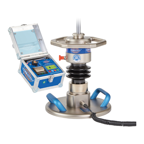
2.7 General View – ‘TERRATEST 5000 BLU’ release mechanism impact protector guide rod release lever inspection window electronic mechanical testing computer loading device handle storage box weight-catching grip GPS antenna (not visible) USB cable port... -
Page 17: Top View Of Control Panel, Testing Computer - 'Terratest 5000 Blu
2.8 Top View of Control Panel, Testing Computer – ‘TERRATEST 5000 BLU’ GPS antenna USB cable port charging socket USB-Stick port (on the back panel) /max. 1.25A button for paper feed control buttons backlit graphic display control lamp thermal printer... -
Page 18: Technical Specifications
‘Robusta’ (box made of air chamber panels and aluminium profiles, external button on the front face) ‘TERRATEST 5000 BLU’ with box for testing computer ‘Robusta’ (box made of air chamber panels and aluminium profiles, external button on the front face) 3.2 Serial Number:... -
Page 19: Load Plate
20 mm Power supply Bluetooth ® transmitter long-lasting, rechargeable Bluetooth ® sensor dome (‘TERRATEST 5000 BLU’ ONLY) battery pack type 8904 7.4V/2.4Ah 3.4 Mechanical Loading Device: 10 kg 15 kg Impact force 7.07 kN ± 1% 10.605 kN ± 1% Impact duration 17 ms ±... -
Page 20: Power Supply
(basic package). A long-lasting, rechargeable, built-in battery pack type 8904 7.4 V/2.4 Ah is located in the sensor dome (‘TERRATEST 5000 BLU’ ONLY). It should be charged with the supplied power cable 9V DC/2A with plugs from LEMO. -
Page 21: Charging Of Testing Computer
Load Plate (‘TERRATEST 5000 BLU’ ONLY) ® To charge the battery pack in the sensor dome (‘TERRATEST 5000 BLU’ ONLY), use the supplied charging cable with LEMO-plugs, and plug it into the LEMO-socket on the sensor dome. Depending on ambient temperature, charging time is approximately 8 hours, when the battery pack is empty. - Page 22 Pulling on the cable may result in damage to the wires. Power Cable, Bluetooth Load Plate ® (‘TERRATEST 5000 BLU’ ONLY): Only the power cable supplied by the manufacturer (SYS1308- 1809-W2E) with LEMO-plugs should be used for charging the Bluetooth® transmitter in the Bluetooth ®...
-
Page 23: Usb Cable Port
When disconnecting the cable always take hold of the plug. Pulling on the cable may cause damage to the wires, fire or electric shock. No tests should be performed while charging the device; doing so may distort test results. 3.11 USB Cable Port The testing computer is equipped with a USB cable port on the partition panel of the storage box. -
Page 24: Measuring Cable
2 meters. It is equipped with two identical 6.35 mm jack plugs. ‘TERRATEST 5000 BLU’: The measuring cable for transferring the sensor signals to the testing computer can be extended to a maximum of 2 meters. It is equipped with two identical plugs with LEMO ‘PUSH-PULL’... - Page 25 Plugs with LEMO ‘PUSH-PULL’ lock (‘TERRATEST 5000 BLU’ ONLY) lock themselves automatically inside the sockets; they can only be disconnected after unlocking. Accordingly, pull only on the plug, never on the cable.
-
Page 26: General Overview: Light Weight Deflectometer
® ■ ‘Continuous measuring mode’ for quick performance of several tests without additional operation of the testing computer, when multiple testing points are close to each other (‘TERRATEST 5000 BLU’ ONLY) ■ Text input function to add notes about material or altitude of the testing point ■... -
Page 27: Dynamic Plate Load Test
4.3 Dynamic Plate Load Test The dynamic plate load test with the Light Weight Deflectometer is a test method during which the ground is subjected to an impact load. This impact load is caused by a weight dropping onto a load plate with a diameter of 30 cm (radius r = 15 cm), which generates a maximum force (F max ) of 7.070 kN. -
Page 28: Calibration
4.5 Calibration Before delivery ‘TERRATEST 4000 USB’ and ‘TERRATEST 5000 BLU’ are calibrated according to German ‘Technical Test Code for Soil and Rock Mechanics in Road Constructions TP BF-StB Part B 8.3’. During calibration all components of the device, such as the load plate with integrated sensor, the loading device and the electronic testing computer, are attuned specifically to one another. -
Page 29: Proposal For The Correlation Of
German Federal Road Research Institute (Bundesanstalt für Straßenbau). Send the device back to TERRATEST GmbH for calibration at least once a year, otherwise test results may be imprecise. Test results of a device that has not been calibrated, or of a device with an expired calibration date, must not be used for evaluating the bearing capacity of soil and rock. - Page 30 For every static plate load test at least three dynamic tests must be performed. TERRATEST GmbH shall not be liable for any damage, consequential damage, or even financial loss that occurs as a result of improper use of the device and / or lack of professional knowledge when evaluating the test data.
-
Page 31: Determining The Residual Compaction
4.9 Determining the Residual Compaction If three individual curves are shown on the protocol printout (see Figure 1) and if the Smax value of the individual settlements decreases significantly, re-compaction has occurred caused by the test; further compaction work is usually necessary. In this case we recommend improving the compaction at the same place by performing 15 more impact drops with the Light Weight Deflectometer. -
Page 32: Test Execution 'Terratest 4000 Usb
‘STATUS REQUEST’. When turning on the testing computer with the backlight off, the start screen will show the ‘TERRATEST 4000 USB’ logo and the firmware version number for approximately three seconds, before it switches T E R R A T E S T 4 0 0 0 automatically to ‘STATUS REQUEST’. - Page 33 The confirmed entry will be shown in the ‘TEXT ENTRY’ field of the protocol printout and in the ‘Comments’ field of the ‘TERRATEST 2.0’ software. If you precede the text entry, e.g.
- Page 34 Regularly check that the transportation lock of the drop weight is functioning properly. If you notice signs of wear, stop using the device immediately. Send the device back to TERRATEST for the transportation lock to be repaired or replaced. Put on hearing protectors before the first drop. Hearing protectors must be worn when operating the Light Weight Deflectometer, since the noise level may rise over 85 dB during the test.
- Page 35 A longer audio signal (a beep lasting one second) announces the end of the test and the recording of measured data on both the internal memory and the USB stick (if in use). All test data including settlement curves, GPS coordinates, date, time, serial number, device type, and the test results themselves, are now saved.
-
Page 36: Printing The Test Protocol
Use only thermal paper; the coated, heat-sensitive side must face will show green. outwards. Suitable paper rolls can be obtained in most office supply stores, or ordered at TERRATEST GmbH. Specifications of paper rolls: Thermal paper roll Width 57 mm... - Page 37 Printout of the Test Protocol serial number device name device type German standard time of test date of test GPS coordinates of testing point dynamic deflection module zero point test area progress of settlement with the three settlement curves maximum settlement maximum speed of immersion average maximum...
-
Page 38: Test Execution 'Terratest 5000 Blu
® When turning on the testing computer with the backlight off, the start screen will show the ‘TERRATEST 5000 BLU’ logo as well as the version number of the firmware for approximately three seconds, before T E R R A T E S T 5 0 0 0 progressing automatically to ‘STATUS REQUEST’. - Page 39 The confirmed entry will be shown in the ‘TEXT ENTRY’ field of the protocol printout and in the ‘Comments’ field of the ‘TERRATEST 2.0’ software. If you precede the text entry, e.g.
- Page 40 Regularly check that the transportation lock of the drop weight is functioning properly. If you notice signs of wear, stop using the device immediately. Send the device back to TERRATEST for the transportation lock to be repaired or replaced. Put on hearing protectors before the first drop. Hearing protectors must be worn when operating the Light Weight Deflectometer, since the noise level may rise over 85 dB during the test.
- Page 41 After performing the third test, the device will show the settlements s4, s5 and s6 in mm, as well as the respective settlement curves. Additionally, the final result, the Evd value in MN/m , will be shown and will also be announced, rounded to whole numbers in MN/m , via the voice output.
-
Page 42: Connecting Bluetooth Load Plate To Testing Computer With The Measuring Cable
6.3 Connecting Bluetooth Load Plate to Testing Computer ® with the Measuring Cable If the Bluetooth connection between Bluetooth load plate and testing ® ® computer is not desired, or not possible, the connection can also be established with a measuring cable. Turn on the transmission unit of the Bluetooth sensor dome by pressing ®... -
Page 43: Continuous Measuring Mode
‘Magic Eye’ GREEN Whenever the Bluetooth sensor dome is ready to start a test, the ‘magic ® eye’ will show green. After every drop the test data will be transferred to the testing computer. During data transfer the ‘magic eye’ will switch to blue. -
Page 44: Printing The Test Protocol
Use only thermal paper; the coated, heat-sensitive side must face will show green. outwards. Suitable paper rolls can be obtained in most office supply stores, or ordered at TERRATEST GmbH. Specifications of paper rolls: Thermal paper roll Width 57 mm... - Page 45 Printout of the Test Protocol serial number device name device type German standard time of test date of test GPS coordinates of testing point dynamic deflection module zero point test area progress of settlement with the three settlement curves maximum settlement maximum speed of immersion average maximum...
-
Page 46: Menu Guidance
7. Menu Guidance D I 3 0 / 0 6 / 1 3 1 5 : 5 0 : 2 2 7.1 Menu ‘USB STICK’ 6 , 3 V All commercially available USB sticks can be used. However, pay USB STICK NOT AVAILABLE attention to the height of the USB stick;... -
Page 47: Subsequent Printing Of Test Data
→ 7.2 Subsequent Printing of Test Data USB STICK LANGUAGE GPS / TIME Turn on the device by pressing the ‘START’ button. Then enter the ‘MAIN INTERNAL MEMORY SERVICE MENU’ by pressing the ‘SELECT’ button. Use the ‘SELECT’ button to →... -
Page 48: Language Menu
7.3 Language Menu USB STICK → LANGUAGE GPS / TIME Turn on the device by pressing the ‘START’ button. Then enter the ‘MAIN INTERNAL MEMORY MENU’ by pressing the ‘SELECT’ button. Use the ‘SELECT’ button to SERVICE move the arrow and select ‘LANGUAGE’ from the menu. Then press the →... -
Page 49: Menu Gps / Time
7.4 Menu GPS / TIME D I 3 0 / 0 6 / 1 3 1 5 : 5 0 : 2 2 7.4.1 GPS Reception 6 , 3 V The device is delivered with the status set to ‘GPS IS ON’. 1 0 0 GPS NOT AVAILABLE The GPS reception is automatically activated when turning on the device,... -
Page 50: Gps On / Gps Off
7.4.3 GPS ON / GPS OFF USB STICK LANGUAGE → GPS / TIME Turn on the device by pressing the ‘START’ button. Then enter the ‘MAIN INTERNAL MEMORY MENU’ by pressing the ‘SELECT’ button. Use the ‘SELECT’ button to SERVICE move the arrow and select ‘GPS / TIME’... -
Page 51: Date And Time
7.4.5 Date and Time USB STICK LANGUAGE → GPS / TIME The device is delivered with the status set to ‘TIME IS GPS TIME’. Weekday, INTERNAL MEMORY date and switch-on time will be shown automatically during ‘STATUS SERVICE REQUEST’, when turning on the device. This data is globally imported via →... -
Page 52: Time Zones
7.4.7 Time Zones USB STICK LANGUAGE → GPS / TIME The testing computer is delivered with the time zone set to ‘GMT + 01:00 h’ INTERNAL MEMORY (GMT = Greenwich Mean Time). This setting corresponds to Central SERVICE European Winter Time, imported via the corresponding satellites by the →... -
Page 53: Internal Memory
Position the arrow on ‘SEND TO PC’ and press the ‘START’ (SET) button ERASE MEMORY to load the test data directly into the ‘TERRATEST 2.0’ software. Establish the USB connection between the testing computer and PC by plugging in →... -
Page 54: Internal Memory To External Media
Launch the ‘TERRATEST 2.0’ software and click on the field ‘Read testing computer’. All data records saved in the internal memory will then be copied to the PC. You can then undertake an analysis of the test data on your PC. All test data will be retained in the internal memory. -
Page 55: Service
7.6 Service USB STICK LANGUAGE GPS / TIME 7.6.1 Input Test INTERNAL MEMORY → SERVICE Turn on the device by pressing the ‘START’ button. Enter the ‘MAIN → EXIT MENU’ by pressing the ‘SELECT’ button. Use the ‘SELECT’ button to MAIN MENU move the arrow and select ‘SERVICE’... -
Page 56: Device Type 10 / 15 Kg
7.6.3 Device Type 10 / 15 Kg INPUT TEST VERSION → 10/15/20 Kg MODE Turn on the device by pressing the ‘START’ button. Enter the ‘MAIN DISPLAY CONTRAST MENU’ by pressing the ‘SELECT’ button. Use the ‘SELECT’ button to PC SERVICE CALIBRATION MODE move the arrow and select ‘SERVICE’... -
Page 57: Voice Output: Sound Service ('Terratest 5000 Blu' Only)
‘TEST SOUND’ or ‘TEST NEXT SOUND’ from the menu. Press the ‘START’ button (SET). A voice instruction in the selected volume will follow. The menu entry ‘LOAD FILES’ permits TERRATEST GmbH to install other language versions (if available). Only one language per device can be used at a time. -
Page 58: Bt Sensor Dome ('Terratest 5000 Blu' Only)
7.6.7 BT Sensor Dome - Connection (‘TERRATEST 5000 BLU’ ONLY) PRINT FROM USB-STICK LANGUAGE GPS / TIME 7.6.7.1 Stand-by Time INTERNAL MEMORY SERVICE → CONNECTION The testing computer can be operated in two measuring modes: ‘SINGLE → EXIT MEASURING MODE’ and ‘CONTINUOUS MEASURING MODE’. If several... -
Page 59: Terratest 2.0' Software
8.1 Uninstalling the ‘TERRATEST 2.0’ Software If an older version of ‘TERRATEST 2.0’ is already installed on your PC, it must be uninstalled before the installation of the current version. The new software cannot be installed otherwise. Use the uninstall routine of the software as follows: Go to START ->... - Page 60 Confirm your selection by clicking ‘Next’. The confirmation screen will open. Confirm by clicking ‘Next’. Next, the main installation process of the ‘TERRATEST 2.0’ software will start. This may take a few minutes. A new window will open, confirming the successful...
-
Page 61: Using The 'Terratest 2.0' Software
TERRATEST logo on a white square. To start the software go to START -> PROGRAMS -> TERRATEST -> TERRATEST 2.0 or simply double-click on the TERRATEST logo on the desktop. The main screen of the ‘TERRATEST 2.0’ software will open automatically. -
Page 62: Editing Logo And Company Data
8.3.2 Prepare USB Stick The Light Weight Deflectometers ‘TERRATEST 4000 USB’ and ‘TERRATEST 5000 BLU’ are supplied with a USB stick, which is already prepared for recording the test data. If you want to use other USB sticks, these must be empty. -
Page 63: Reading The Usb Stick
If you would like to include several test series in one test data list, save all required data records in the same folder. Then, load it into the ‘TERRATEST 2.0’ software by clicking on the button ‘LOAD TEST DATA’. -
Page 64: Reading The Chip Card
If you would like to include several test series in one test data list, save all required data records in the same folder. Then, load it into the ‘TERRATEST 2.0’ software by clicking on the button ‘LOAD TEST DATA’. -
Page 65: Converting Old Test Data
The data format for saving the test data on the PC has been modified, in order to use the new features of the ‘TERRATEST 2.0’ software. To be able to use older test data stored on the PC using a previous version of the ‘TERRATEST’... -
Page 66: Test Protocol Of Individual Tests
8.3.6 Test Protocol of Individual Tests The test protocol (for an example, see page 70) is divided into four areas: Protocol heading, with general information about the test and the test instrument Test result chart, with the recorded test results and the required Evd value Settlement curves, with a presentation of the course of the three settlement curves, as well as a picture of the testing point, if added Google... - Page 67 The test data list on the left specifies all individual measurements loaded to the PC. A satellite picture of the testing point is displayed on the bottom right for the selected test. On the top right the individual data record with its three settlement curves is shown.
-
Page 69: Test Data Loading
If you would like to include several test series in one test data list, save all required data records in the same folder. Then, load it into the ‘TERRATEST 2.0’ software by clicking on the button ‘LOAD TEST DATA’. -
Page 70: Loading Data From Testing Computer
Position the arrow on ‘MEMORY TO PC’ and press the ‘START’ button EXIT EXIT (SET) to load the test data directly to the ‘TERRATEST 2.0’ software. Upon establishing a successful USB connection, ‘PC connected’ will appear on the display. Click on the button ‘READ TESTING COMPUTER’. - Page 71 To download the test data from the testing computer, connect it to the USB cable port of your computer and establish the connection via the menu of the testing computer.
-
Page 72: Driver Installation For Testing Computer
PC for the first time, the corresponding driver will need be installed from the supplied CD ROM ‘TERRATEST 2.0’. Insert the CD ROM ‘TERRATEST 2.0’ into the CD drive of your PC. When connecting the testing computer to your PC you will automatically be informed about the required driver. - Page 73 Since the driver has not been certified by Microsoft for MS Windows , you will be asked if ® ® you would like to continue with the installation. Confirm by clicking ‘CONTINUE INSTALLATION’. The driver will then be installed. To finish, confirm the driver installation with ‘COMPLETE’.
-
Page 74: Edit / Save Protocol
8.3.10 Edit / Save Protocol In order to edit the test protocols of individual tests, left-click on the desired individual data record from the test data list in the left window. If you would like to select several successive data records, left-click on the first and the last data record, while holding down the Shift key. - Page 75 <comment>_<date>_<time>>_[<nr>].tc5. This can be done at a later time in the ‘TERRATEST 2.0’ software by preceding the text in the field ‘COMMENTS’ with a slash ‘/’. If a slash ‘/’ is entered in the text input function on the testing computer, or in the comments field on the PC, the data can subsequently be filtered via the ‘SEARCH’...
- Page 76 The pen symbol marks the data records ready for editing. Only those featuring the pen symbol will be saved or printed. Drop-down menus facilitate the entry of soil characteristics. However, individual descriptions can be entered as well.
-
Page 77: Print Protocol / Export As Pdf File
Test protocol with manually entered data. All entered data, except ‘LOCATION TESTING POINT’ and ‘COMMENTS’, will automatically be applied to all data records marked with a pen symbol. If the required Evd value has been entered manually, the discrepancy between the required and the measured value will be displayed automatically. -
Page 78: Create Statistical Analysis
8.3.12 Create Statistical Analysis For the statistical analysis of various tests, left-click on the individual tests in the test data list on the left hand side. If you would like to select several successive data records, left-click on the first and the last data record, while holding down the Shift key. -
Page 79: Print Statistical Analysis / Export As Pdf File
8.3.13 Print Statistical Analysis / Export as PDF File To print the statistical analysis, click the button ‘PRINT ALL DATA RECORDS’ on the bottom right. To save the statistical analysis as a PDF, use the button ‘ALL DATA RECORDS AS PDF’. 8.3.14 Google Maps Statistics Overview ®... - Page 80 Statistical analysis including data that was automatically copied from the individual data records.
-
Page 82: Select Language
8.3.15 Select language You can select the desired language of the software by double-clicking on the version number. After double-clicking on the version number, the language selection will open. -
Page 83: Search Function For Individual Tests
8.3.16 Search Function for Individual Tests The search function can be used only if the test data has previously been uploaded to the ‘TERRATEST 2.0’ program. Activate the search function by clicking on the ‘SEARCH’ button on top of the list which shows all uploaded tests. - Page 84 Keyword Search If, instead of the list of all available tests, you want to see only those tests which contain a certain keyword in the ‘COMMENTS’ or ‘CONSTRUCTION PROJECT’ field, you can activate the relevant filter by checking the box in front of the filter name and entering the keyword in the filter description field. If you enter ‘MISSISSIPPI’...
-
Page 85: Warranty
1.2. TERRATEST GmbH guarantees that under normal circumstances every ‘system’ (see below) which is sold for the first time by TERRATEST GmbH or one of our dealers in a country of the European Economic Area or Switzerland (our trading area) will be free of defects in material or workmanship for the duration of time noted on the warranty card supplied with the system. - Page 86 2.1. Exclusions This limited warranty does not cover: 2.1.1. Products which were not manufactured by TERRATEST GmbH or which were originally sold to an end user in a county outside the area in which this warranty applies. 2.1.2. Products which were damaged or rendered inoperable by one of the following ways of utilisation or operating: 2.1.2.1.
- Page 87 2.3. If you make a claim under the warranty, you acknowledge concurrently that no further entitlements against TERRATEST GmbH regarding the purchase or use of your system exist other than those warranty and compensation benefits described above.
-
Page 88: Ec Declaration Of Conformity
EC Low Voltage Directive, by virtue of its design and construction, as well as its configuration, which was placed on the market by us, TERRATEST GmbH. This declaration shall become null and void should any alterations be made to the product without our prior agreement. -
Page 89: Standards
11. Standards 11.1 ZTV-E-StB 09 German Road and Transportation Research Association (Issue 2009) ‘..3.4.7.2 Requirements for deflection modulus The requirements detailed below are based on the 10% minimum quantile. When constructing roads corresponding to Construction Classes SV, or I to IV on frost-free subsoil or substructure, it is necessary to obtain a deflection modulus of at least E = 120 MN/m or alternatively E... -
Page 90: Ril 836 - Deutsche Bahn Ag
11.2 RIL 836 – German National Railway Company Deutsche Bahn AG Extract from German standard RIL 836 - Deutsche Bahn AG 836.501 RIL 836- Earthwork structures – design, construction and maintenance Seite 10 Standard for embankments and cuttings Requirements for railway track substructure under embankments or cuttings Type of railway line Top soil Protective layer... -
Page 91: Rvs 08.03.04
11.3 RVS 08.03.04 RVS 08.03.04 Austrian Association for Research on Road · Rail · Transport Extract from Austrian standard RVS 08.03.04 – Compaction Tests by means of the Dynamic Plate Load Test; Issue 1st March 2008; Austrian Association for Research on Road · Rail · Transport 8.1 Conversion of Minimum Requirements A minimum requirement for the deformation modulus Ev1 of the static plate load test can also be checked with the dynamic plate load test. -
Page 92: Cable Layout
12. Cable Layout 12.1 LEMO Push-Pull Connection (‘TERRATEST 5000 BLU’ ONLY) 12.1.1 Female Socket Codification Testing Computer Bluetooth Sensor Dome ® green black white brown green 12.1.1 Male Plug Codification Wire white yellow 12.2 Jack Connection (‘TERRATEST 4000 USB’ ONLY) 12.2.1 Female Socket... - Page 94 TERRATEST GmbH Friedrich-Wolf-Strasse 13 · 16515 Oranienburg GERMANY Phone: +49 3301 700 700 · Fax: + 49 3301 55 44 0 www.terratest.de · info@terratest.de...
Need help?
Do you have a question about the 5000 BLU and is the answer not in the manual?
Questions and answers