
Related Manuals for OCEM 3 Series

Summary of Contents for OCEM 3 Series
- Page 1 Use and Maintenance Manual Precision Approach Path Indicator ocem...
- Page 2 OCEM Airfield Technology, and any other name/brand associated with products OCEM Airfield Technology mentioned or indicated in this document, are trademarks or registered by OCEM Airfield Technology. The rights of third parties on each registered trade mark mentioned in this document are the property of their respective owners.
-
Page 3: Table Of Contents
LED PAPI 66 GENERAL INFORMATION Package content Manual reference guide Safety instructions Safety symbols 1.5 Definition of operator Limited warranty CE marking 1.8 Confidentiality, industrial property rights 1.9 Disposal 1.10 Article identification 1.11 Photo-biological risk FIXTURE DESCRIPTION 2.1 General characteristics Content of delivery Article number 2.4 Lens heating optional device 2.5 Tilt switch optional device 2.6 Tilt switch optional device (mercury-free) - Page 4 LED PAPI 66 Page intentionally left blank UT-MT-0972_1.0_19-09-2022 (EN) Use and Maintenance Manual...
-
Page 5: General Information
LED PAPI 66 GENERAL INFORMATION Package content The LED PAPI 66 of OCEM Airfield Technology is a signalling system composed of overhead light LED units PAPI Series 3 type current-powered (6.6A - Style B), with optical indicator function of the gradient approach (VASI | Visual Approach Slope Indicator). The system provides to flight crews informations concerning both the adopted approach angle and the trajectory to follow. The device is designed in compliance with: ● ICAO Annex 14 Volume 1 | EASA Certification Specifications and Guidance Material for Aerodrome Design (CS-ADR-DSN) ● FAA AC 150/5345-28 Precision Approach Path indicator (PAPI) Systems: L-880 - System composed of 4 light units; L-881 - System composed of 2 light units (Style B: system current-powered through series circuit; Class I: system operating from -31 degrees Fahrenheit (F) [-35 °C] to 131 degrees Fahrenheit (F) [+55 °C]). Immediately check for visible damages of the containers and of the containing parts. Carefully remove the device and check for visible damages. Before proceeding read all warnings on the packaging. -
Page 6: Manual Reference Guide
LED PAPI 66 Manual reference guide This document contains all the information related to the equipment and describes the procedures to follow during the installation of the product and during ordinary maintenance. The document is indented for all operators that must intervene on the equipment. This document does not replace in any manner applicable laws, rules or regulations, included the standards FAA and ICAO. The precautions provided in the manual are always preceded by a symbol as illustrated below: Indicates the warnings, the notes, the suggestions and other points on which is intended to draw the attention of the reader. - Page 7 LED PAPI 66 Always proceed with the utmost attention. Safe intervention procedures indicated aim to protect the operator against possible risks and to preserve the fixture from any damages. SAFE INTERVENTION ON THE FIXTURE POWERED BY SERIES CIRCUIT Operate in this way: ● Switch off the constant current regulator ● Disconnect the supply plug from the related socket of the secondary of the isolation transformer ●...
-
Page 8: Safety Symbols
All operations on equipments and on its internal parts must be performed by professional staff, properly trained for Cardio Pulmonary Resuscitation (CPR) techniques. Never operate on devices if there is not at least another operator properly trained for CPR techniques. Check that Operators do not operate outside their own specific fields of competence and responsibility. OCEM Airfield Technology declines any and all liability arising from wrong operations carried out by untrained personnel in the use of the devices, or deriving from the non compliance of general safety standards. UT-MT-0972_1.0_19-09-2022 (EN) Use and Maintenance Manual... -
Page 9: Limited Warranty
Product, only on condition that this Product is resold as NEW and with the original packaging. Each change and/or tampering made to the product immediately terminates the warranty. OCEM Airfield Technology cannot be held responsible for any damage to items or persons deriving from the failure to comply with instructions relating to installation, use and maintenance of the product, and to the installation and storage environmental conditions stipulated by the Manufacturer or by applicable rules regarding electrical devices and systems. -
Page 10: Ce Marking
LED PAPI 66 CE marking This equipment complies with the requirements of European legislation for the CE marking. The user should carefully read this document and respect all the requirements quoted. This equipment meet the requirements in relation to health and safety of the main EC directives, and in particular of the EMC Directive on electromagnetic compatibility (2014/30/EU) and of the LV Directive relating to electrical equipment designed for use within certain voltage limits (2014/35/EU). Confidentiality, industrial property rights The Customer needs to adopt the maximum confidentiality with respect to all the information of technical nature (including, by way of example and not exhaustively, plans, programmes, documentation, formulas, recipes, setting and correspondence) received by the Supplier or in any case assimilated or gained during the conclusion of the Contract of sale. Any right regarding intellectual and industrial property connected to equipment and to any other element included in the supplied Goods as indicated in the Contract remain exclusive property of the Supplier. Disposal At the end of use, the user must confer all the waste in suitable differentiated waste collection centres. It is the responsibility of the user the correct disposal of the equipment in accordance with the WEEE Directive and with the respective national laws in force at the time of disposal. These equipments must never be disposed of in the household waste. 1.10 Article identification On each equipment there is an identification plate of the article, where the article code is reported; on the plate there are additional data: the name of the model, employments or use, power supply features, any trademarks and/or marks that attest the agreement of the equipment to specific regulations or legislations. UT-MT-0972_1.0_19-09-2022 (EN) Use and Maintenance Manual... -
Page 11: Photo-Biological Risk
LED PAPI 66 1.11 Photo-biological risk The fixtures LED PAPI 66 are designed and manufactured in compliance with current regulations, but if used unsafely or without precautions, the light emitted by the fixture, reaching even high levels of intensity, can be harmful not only to those who use the light fixture locally, but for anyone within the light beam range. The optical radiation issued by the equipment does not present any particular photo-biological risks, however can be harmful. Don’t look directly inside the light source during high intensity operation. Wear appropriate personal protective equipment (goggles or similar protections). UT-MT-0972_1.0_19-09-2022 (EN) Use and Maintenance Manual... - Page 12 LED PAPI 66 Page intentionally left blank UT-MT-0972_1.0_19-09-2022 (EN) Use and Maintenance Manual...
-
Page 13: Fixture Description General Characteristics
LED PAPI 66 FIXTURE DESCRIPTION General characteristics The LED PAPI 66 unit are designed for the purpose of providing visual guidance to aircrafts in the bichromatic approach flash signalling: ● Four-light PAPI the system consists of 4 LHA units (Light Head Assembly) current-powered in environments with temperatures between -35 °C [-31 °F] and +55 °C [+131 °F]. ● Two-light PAPI (A-PAPI) the system consists of 2 LHA units (Light Head Assembly) current-powered in environments with temperatures between -35 °C [-31 °F] and +55 °C [+131 °F]. The innovative optics reach the lowest consumption levels of the sector, uniform intensity and red/white rapid transition to provide the pilot with an accurate reporting on the glideslope approaching the runway. - Page 14 LED PAPI 66 Available with supports for fixed installation [P0] with frangible coupling, the LED PAPI 66 system is designed to be used in various scenarios. The LED PAPI 66 is compliant with the rules: ICAO (Annex 14 Volume 1) EASA (CS-ADR-DSN) FAA (AC150/5345-28) The fixtures LED PAPI 66 described in this manual have been designed to be installed on the concrete basis. Typical installation suggested by FAA: minimum depth of 914 mm [36”] or of 305 mm [12”] below the frost line, if greater;...
-
Page 15: Content Of Delivery
LED PAPI 66 The units communicate with each other by means of a CAN type communication bus (CAN BUS). In the PAPI system is included a digital clinometer to perform the alignment and the adjustment of the LHA unit. For further information on the use of the clinometer, please refer to the manual included in the supply. Calibrate the clinometer before each use. Clinometer calibration can be easily performed by the maintenance personnel, carefully following the instrument's instructions. Content of delivery L-880 L-881 PAPI/4 LHA A-PAPI/2 LHA 4 LIGHTS 2 LIGHTS LHA - Light Head Assembly Pre-cabled unit with cables (power and control) 183 cm [6 ft] in length with overmolded connectors L-823... -
Page 16: Article Number
LED PAPI 66 Article number example: AV‑PAPI 4 - P0 - 66 - 0 - 1 Regulations/Dimension ICAO Abbreviated-PAPI 2-LHA (Light Head Assembly) FAA 2-LHA (Light Head Assembly) FAA/ICAO 4-LHA (Light Head Assembly) Replacement optical unit (only LHA - Light Head Assembly) Installation P0 = Fixed Supply 66 = CCR 3 and 5 step from 2.8 A to 6.6 A (FAA Style B) Options 0 = None 4 = Heated lens* 8 = Tilt switch 12 = Heated lens and tilt switch (version FAA std)** Colour Orange FAA... -
Page 17: Lens Heating Optional Device
LED PAPI 66 Lens heating optional device The LHA unit of LED PAPI 66 system can be equipped with optional lens heaters. The heater is controlled by a microprocessor system to delete any problem caused by repeated and close on-off cycles and to optimise the relative consumption. The heater is always activated at full power for 25 minutes after the unit is powered on. Subsequently it remains powered at low power to keep the lens warm at about 5 ° above ambient temperature. In any case, if the lens temperature exceeds a certain threshold, the heater is deactivated. Tilt switch optional device The effectiveness of the LED PAPI 66 system is determined by the correct inclination of the light beams of the LHA units installed. If a LHA unit loses the alignment of the correct inclination, can provide incorrect indications to the pilot approaching. Each LHA unit can be equipped with a tilt switch optional device of the LHA unit and, if this deviates by the correct inclination set during installation, the whole LHA units system is deactivated (with a delay of 10-30 seconds, to avoid detection mistakes due to temporary external conditions, such as wind or vibrations). The PAPI system is designed to operate in fail-safe mode: when the LHA units are equipped with tilt switch device, the system becomes operational only if all LHA units are correctly inclined. Tilt switch optional device (mercury-free) The LED PAPI 66 system can be equipped with tilt switch optional device mercury-free type (for applications in areas in which mercury is listed among the substances subject to restrictions). The operation of these components is similar to the one already described in the paragraph related to the standard tilt. Behaviour in case of fault Below are listed the possible types of faults and the behaviour of the failed unit and of other units of the system in the various cases: ●... -
Page 18: Wiring
LED PAPI 66 Wiring To wire the LED PAPI 66 system properly use the cables supplied already attested to the equipment: ● Power cable equipped with overmolded connector L-823 Style 1 to connect to the secondary of the isolation transformer (L-830, L-831) 150 W. ● Monitoring cable (optional) equipped with overmolded connector L-823 Style 6 to connect to the secondary of the isolation transformer (L-830, L-831) 45 W. ● Communication cable (bus CAN). The isolation transformers necessary for the functioning of the unit are not included in the supply. It is the customer’s responsibility to arrange appropriate certified equipment to supply the units. -
Page 19: Installation
LED PAPI 66 INSTALLATION Fixture placement The signalling devices, in combination with horizontal and vertical fixtures, provide information to the pilots and therefore represent a fundamental driving aid. These devices must always be in operating condition and must be clean, maintained and, if necessary, replaced as soon as their visibility is affected. The chromatic features of signalling optical devices must be compliant with the dispositions of competent bodies and with the regulations in force. For the features of the fixtures always refer to the requirements of the relevant Standards: • FAA AC150/5345-28H Precision Approach Path indicator (PAPI) Systems: L-880 - System consisting of 4 light units; L-881 - System consisting of 2 light units •... -
Page 20: Permanent Installation
LED PAPI 66 Permanent installation Store the device in its original packaging until the time of installation. Proceed assembling the device and check the supply features before proceeding with the installation. Use the fixture only in combination with concrete foundations with adequate characteristics (in accordance to specifications FAA and ICAO). At the end of installation check the proper alignment of the fixture. In case of incorrect positioning optical misalignments of light beams may occur. - Page 21 LED PAPI 66 Position the LHA unit on the supports suitably fixed to the ground and insert the alignment washer (3a) and the increased washer (3b). Screw, without tightening, the upper nut (3c). If on the support surface of the tool there is dust or dirt, carefully clean the surface before proceeding. Position the clinometer on the front transverse tubular in centred position. Act on the lower nuts (3c) and (3d) of the front supports to adjust the alignment (0°) of the unit. Position the clinometer on the rear support bracket, by fastening it with 2 knurled screws (supplied with the clinometer). Act on the lower nuts (3c) and (3d) of the rear support to adjust the tilt angle (i) of the unit.
- Page 22 LED PAPI 66 Repeat the verification/adjustment operations of the alignment (0°) of the LHA unit. If necessary, proceed to fine adjustments of the alignment by acting on both supports: move the lower nuts of the same amount in opposite directions until obtaining the alignment (0°). Repeat the verification/adjustment operations of the tilt (i) of the LHA unit. If necessary, proceed to fine adjustments of the tilt (i) and proceed to a further verification of the alignment (0°).
- Page 23 LED PAPI 66 Pay attention not to damage the cables of the LHA units during installation operations. Before connecting, protect the cables of the LHA units by using the wrinkled tube supplied. The number and the type of input cables can change depending on the configuration. Protect the input cables to each LHA unit proceeding as follows: ●...
- Page 24 LED PAPI 66 Make the connections of each LHA unit proceeding as follows: ● The power cable (L-823 Style 1) to the secondary of the isolation transformer 150 W (not included in the supply) inserted on the series circuit; ● The communication cable CAN BUS in parallel with the cables CAN BUS of other LHA units of the system (connect together the wires of the same colour), extending them by means of the three-core cable supplied performing watertightness connections; ● The cable of the optional monitoring (L-823 Style 6) to the external monitoring device; in case of Power Line communication connect the external monitoring device to the primary circuit by means of isolation transformer from 45 W (not included in the supply). At the end of installation, carry out a function test of each unit. Position a screen (8a) in front of LHA units (ex. a panel of paper/cardboard) and check that the units work properly.
-
Page 25: Adjustments And Maintenance
LED PAPI 66 ADJUSTMENTS AND MAINTENANCE Before carrying out any intervention on the device, cut off all external power sources and place appropriate work-in-progress warnings on the systems. Wait for the discharging time (at least 5 min) and check using appropriate instruments that there are no residual energies before accessing the electrical equipment. -
Page 26: Removal Of The Cover
Wait for the discharging time (at least 5 minutes) and check using appropriate instruments that there are no residual energies before accessing the electrical equipment. Every time that the fixture body is opened, all cables must be checked. If necessary, use only original spare parts by OCEM Airfield Technology. Whenever the LED PAPI 66 fixture is opened, it must be ensured that: ●... -
Page 27: Cleaning Of The Lens
LED PAPI 66 Cleaning of the lens Before carrying out any intervention on the fixture, cut off all external power sources and place appropriate work-in-progress warnings on the systems. Wait for the discharging time (at least 5 minutes) and check using appropriate instruments that there are no residual energies before accessing the electrical equipment. -
Page 28: Replacement Of The Led Module Assembly
LED PAPI 66 Replacement of the Led MODULE assembly Before carrying out any intervention on the fixture, cut off all external power sources and place appropriate work-in-progress warnings on the systems. Wait for the discharging time (at least 5 minutes) and check using appropriate instruments that there are no residual energies before accessing the electrical equipment. - Page 29 LED PAPI 66 Check that the replacement LED module match the desired colour configuration. ATTENTION: Check the position references of the LED module before definitively fasten and connect the module. Do not use solvent or diluent products. Remove any condensation accumulated during operations: if necessary, dry thoroughly the internal sides of the device.
-
Page 30: Replacement Of The Pcba Led Driver Board
LED PAPI 66 Replacement of the PCBA LED Driver Board Before carrying out any intervention on the fixture, cut off all external power sources and place appropriate work-in-progress warnings on the systems. Wait for the discharging time (at least 5 minutes) and check using appropriate instruments that there are no residual energies before accessing the electrical equipment. - Page 31 LED PAPI 66 Before disconnecting the board mark on the connectors the position references in order to restore the exact configuration of the connection (position and orientation compared with the board). Unscrew the self-locking nuts (3a). Disconnect the connectors from the PCBA LED Driver Board and remove the board from its seat paying the utmost caution. If necessary, carefully clean the connection box (4a). Do not use solvent or diluent products. Remove any condensation accumulated during operations: if necessary, dry thoroughly the internal sides of the device.
- Page 32 LED PAPI 66 Fasten the PCB LED driver (5a) to its supports. Before connecting the electronic board configure the component for use in the field: with an appropriate adjustment tool act on the selector (S1) and select the identifier of the LHA unit on which is intended to install the electronic board. Reconnect the connectors to the PCBA LED Driver Board, respecting the configuration previously marked.
-
Page 33: Replacement Of The Pcba Ccr Interface Board
LED PAPI 66 Replacement of the PCBA CCR Interface Board Before carrying out any intervention on the fixture, cut off all external power sources and place appropriate work-in-progress warnings on the systems. Wait for the discharging time (at least 5 minutes) and check using appropriate instruments that there are no residual energies before accessing the electrical equipment. - Page 34 LED PAPI 66 Before disconnecting the board mark on the connectors the position references in order to restore the exact configuration of the connection (position and orientation compared with the board). Disconnect the connector PWR/CTR (J8) of the electronic board (3a). Disconnect the connectors from the PCBA CCR Interface Board (3b) paying the utmost caution not to damage the cables. Remove the cover (4a) with the board on board and the related cables. Remove any condensation accumulated during operations: if necessary, dry thoroughly the internal sides of the device.
- Page 35 LED PAPI 66 Reconnect the connectors of the PCBA CCR Interface Board (5a) respecting the configuration previously marked. Reconnect the connector PWR/CTR (J8) of the electronic board (5b). Position the cover (6a) of the electronic box and tighten the screws. Reassemble the unit (see the related paragraph in the chapter “ADJUSTMENTS AND MAINTENANCE”). UT-MT-0972_1.0_19-09-2022 (EN) Use and Maintenance Manual...
-
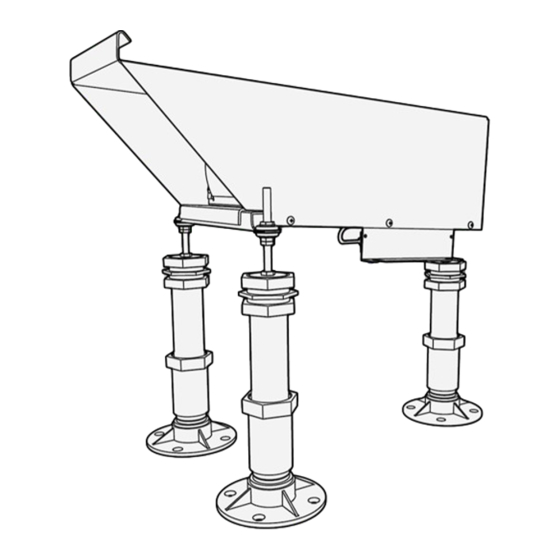
Page 36: Replacement Of The Lha Support
LED PAPI 66 Replacement of the LHA support Before carrying out any intervention on the fixture, cut off all external power sources and place appropriate work-in-progress warnings on the systems. Wait for the discharging time (at least 5 minutes) and check using appropriate instruments that there are no residual energies before accessing the electrical equipment. - Page 37 LED PAPI 66 Before disconnecting, proceed with the operation, detect and record the position of the lower support nut to simplify the pointing operations. Grab the damaged support (3a) with an adjustable wrench in correspondence of the base of the breakable coupling element. Rotate counterclockwise and remove the support of the fastening flange. Arrange the spare part for installation and start manually clockwise tighten the new support to the fastening flange anchored to the base. Grab the support (4a) with an adjustable wrench in correspondence of the base of the breakable coupling element. Rotate clockwise and completely tighten the support to the fastening flange. UT-MT-0972_1.0_19-09-2022 (EN) Use and Maintenance Manual...
- Page 38 LED PAPI 66 Unscrew the upper locking nut (5a) and adjust the lower nut to the correct height, previously detected. Position the LHA unit on the supports and spherical washers. Tighten the three upper locking nuts. Check the proper alignment of the fixture (see the related paragraph in the chapter “ADJUSTMENTS AND MAINTENANCE”). Tighten the screws with the indicated torque values. UT-MT-0972_1.0_19-09-2022 (EN) Use and Maintenance Manual...
-
Page 39: Troubleshooting
Tilt error of one unit. 1. Remove supply to the bar. (the system is designed to switch off all 2. Remove the external cover and open the electronic box of any the units when a unit has an inclination unit. going outside accessible limits) 3. Supply the bar. 4. On the LED driver board there is a red LED (D22): if steady on it indicates that the fault is on the unit present, if it is flashing, the number of flashes indicates the number of the faulty unit. 5. On the unit that faces the problem, check the tilt angle according to the Paragraph 3.2 point 5, therefore restore the position of the tilt error detector (Paragraph 3.2 point 6). If after trying the proposed solutions the problem persists, contact OCEM Customer Service. UT-MT-0972_1.0_19-09-2022 (EN) Use and Maintenance Manual... - Page 40 9. Supply the bar. 10. If the problem persists, remove supply to the bar and replace the red LED module (according to the Paragraph 4.4). 11. Supply the bar. 12. If the problem persists, remove supply to the bar and replace the white LED module (Paragraph 4.4). ATTENTION: don’t look directly inside the light source during operation. If after trying the proposed solutions the problem persists contact OCEM Customer Service. When the bar is powered, a unit remains completely switched off, while the others light up and then switch off. The CCR Interface Board is faulty 1. Remove supply to the bar. 2. Remove the external cover and open the electronic box. 3. Supply the bar. 4. Check that the green leds on the LED Driver Board are lit. 5. If they are off, disconnect the bar and replace the CCR Interface Board. The LED Driver Board is faulty 6.
-
Page 41: Block Diagram Of The System
LED PAPI 66 Block diagram of the system UT-MT-0972_1.0_19-09-2022 (EN) Use and Maintenance Manual... -
Page 42: Spare Parts
LED PAPI 66 4.10 Spare parts Always check the version of the fixture installed and the accessories present. LED PAPI 66 fixture Front support Rear support Optical unit. Accessories Code Art. Clinometer UT-MT-0972_1.0_19-09-2022 (EN) Use and Maintenance Manual... - Page 43 LED PAPI 66 4.10.1 Support units Description Fixture Code Code Art. - P 0 - Front support assembly (fixed mounting) AV-PAPI AV-SP-LG6776 █ █ █ █ █ █ Rear support assembly (fixed mounting) AV-PAPI - P 0 - AV-SP-LG6777 █ █ █ █ █ █ Frangible couplings, thread 2” (per 2” EMT) always valid AV-MC-59-E UT-MT-0972_1.0_19-09-2022 (EN) Use and Maintenance Manual...
- Page 44 LED PAPI 66 4.10.2 Optical unit Description Fixture Code Code Art. External fixture cover AV-PAPI (specify colour when ordering) always valid AV-SP-LG7179 AV-PAPI-SP- White LED AV-PAPI module always valid LG7186 Gasket for LED AV-PAPI module always valid AV-SP-LG7751 Replacement kit PCBA CCR Interface Board with rear cover of the AV-PAPI electronic box, terminal board and cable. With AV-PAPI-66-CCR- always valid* monitoring relay for versions equipped with option SM00/ SMMF*. Back cover of the electronic box AV-PAPI always valid AV-SP-LG7183 Terminal boxes 10 circuits (Marathon Special Product) always valid 671 RZ 10 AV-PAPI-SP- Gasket for electrical connections box AV-PAPI always valid...
- Page 45 Contact us OCEM AT +39 051 66 56 611 info@ocem.com...
- Page 46 LED Precision Approach Path Indicator OCEM AT a division of ENERGY TECHNOLOGY S.r.l. Via della Solidarietà, 2/1 - 40056 Valsamoggia (Bologna) - Italy ocem...
Need help?
Do you have a question about the 3 Series and is the answer not in the manual?
Questions and answers