Table of Contents
Advertisement
Quick Links
Advertisement
Table of Contents

Related Manuals for NKE DualSense HeatPro


Summary of Contents for NKE DualSense HeatPro
- Page 1 User Manual NKE DualSense HeatPro...
- Page 2 Note Check delivery for possible damage caused by transport without delay. Should damage be detected, please inform carriers immediately. As our products are subject to continuous improvement, we reserve the right to make changes to this document.
-
Page 3: Table Of Contents
CONTENTS INDUCTION HEATING Operating conditions SAFETY GUIDELINES Safety precautions Safety instructions Safety features INSTALLATION Scope of delivery Unboxing Installation process SETTING UP THE WORKPIECE Choosing the yoke Positioning the magnetic temperature probe(s) OPERATION Temperature Mode, using one sensor Ramp Mode Temperature Mode, using two sensors Time Mode User menu... -
Page 5: Induction Heating
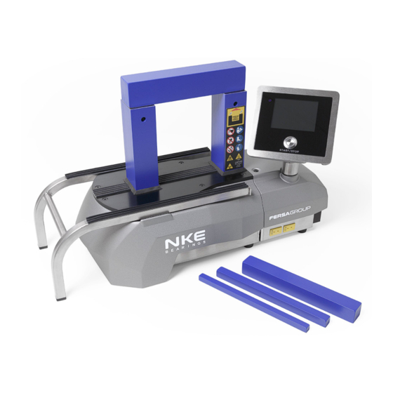
INDUCTION HEATING NKE DualSense HeatPro induction heaters are used to heat rolling bearings. Other metal components forming a closed circuit such as bushings, shrink rings, pulleys and gears can also be heated. This will facilitate mounting where an interference fit is required. -
Page 6: Safety Guidelines
SAFETY GUIDELINES The operating instructions should always be followed when using an induction heater. NKE Bearings shall not be held liable for damages caused by improper handling or by use which does not comply with the designated purpose. Prerequisites for the operator: He/she must be authorised for use of the heater and must be familiar with the safety precautions. -
Page 7: Safety Precautions
SAFETY Since a magnetic field is generated by the induction heater, people wearing 4&5 PRECAUTIONS a pacemaker or other implant device should not work or be in the immediate vicinity of the device. Other sensitive equipment such as wrist watches, magnetic carriers, electronic circuits, etc. -
Page 8: Safety Instructions
SAFETY The user should have an appreciation of the contents of this user manual, and INSTRUCTIONS be familiar with safe workshop practices. Follow the user manual at all times. Ensure that the induction heater operates at the correct supply voltage. If the heater is not supplied with a plug, changes should only be made by a suitably qualified electrician. -
Page 9: Safety Features
MP3x MP2x MP1x types in combination with the different yokes is large. (cm) MP1y MP2y MP3y (cm) MNKE DualSense HeatPro Measurement position (cm) B-field (µT) total MP1x MP2x MP3x MP1y MP2y MP3y Total 50Hz RMS field for magnetic measurement results. -
Page 10: Installation
Heat-resistant gloves User Manual Quickstart guide Note The NKE DualSense HeatPro 400 comes with yokes 10, 14, 25, and 40 included. NKE DualSense HeatPro 500 includes yoke 50 and NKE DualSense HeatPro 600 includes yoke 70. UNBOXING Follow the instructions specific for this heater on the supplied Quickstart guide. If the Quickstart guide is not included in this box, please contact your distributor. -
Page 11: Installation Process
INSTALLATION Ensure that supply voltage and current meet the specifications. These can be found PROCESS on the type plate at the back of the induction heater. Each induction heater is provided with a plug, but there are a large number of plug types. Should the plug not fit your power supply, a suitable plug must be affixed by a qualified electrician. -
Page 12: Setting Up The Workpiece
SETTING UP THE WORKPIECE The workpiece can be set up in two different ways and must never touch the housing. Small objects are to be heated in a vertical position. VERTICAL HORIZONTAL Use appropriate hoisting equipment for heavy components and yokes. Manual lifting of heavy objects is a common cause of injury. -
Page 13: Choosing The Yoke
CHOOSING Choose largest possible yoke which fits the diameter of the workpiece. Position THE YOKE the workpiece onto the yoke and place the yoke with the machine milled surface on the poles of the heater core. Always make sure that the workpiece avoids direct contact with the housing of the heater. -
Page 14: Positioning The Magnetic Temperature Probe(S)
POSITIONING Always use the magnetic temperature probe (hereafter referred to as the THE MAGNETIC ‘probe’) for heating in Temperature Mode or Ramp Mode. TEMPERATURE Place the probe on the workpiece, close to the bore. Make sure that the surface PROBE(S) used for the probe is free of grease and/or oil. -
Page 15: Operation
OPERATION When the induction heater is turned on, the homescreen can show up to four buttons with different modes; Time Mode is always available. Temperature Mode (with 1 sensor) and Ramp Mode will be enabled when one sensor is inserted. An extra Temperature Mode (with 2 sensors) will be enabled when a second sensor is inserted. -
Page 16: Temperature Mode, Using One Sensor
TEMPERATURE MODE, ONE SENSOR 1. PREPARATION To change the Press to change the temperature press A, to temperature (max. 240°C). change the max. power Press when the temperature output press B. is set. Otherwise proceed to Press to change step 2. the max. -
Page 17: Ramp Mode
RAMP MODE 1. PREPARATION To change the Press to change the temperature press A, to temperature (max. 240°C). change the heating time Press when the temperature press B. is set. Otherwise proceed to Press step 2. change the time. Press when the time is set. -
Page 18: Temperature Mode, Using Two Sensors
TEMPERATURE MODE, TWO SENSORS 1. PREPARATION To change the Press to change the temperature press A temperature (max. 240°C). To change the Δ Press when the temperature is set. temperature press B. Otherwise proceed Press to change to step 2. the Δ... -
Page 19: Time Mode
TIME MODE 1. PREPARATION To change the heating Press to change time press A. the time (max. 99:59). Press when the time To change the max. is set. power output press B. Press to change Otherwise proceed to the max. power output. step 2. -
Page 20: User Menu
USER MENU The user menu can be accessed by pressing the start/stop button for 8 seconds. Within this menu the user can view and/or change the following settings: Reset to Factory Settings Calibration Sensor 1 Time Range (MM:SS) Each user setting will be reset The temperature of sensor 1 can be set if it The Time Range can be switched between to its original factory values. -
Page 21: Maintenance
MAINTENANCE Store in a dry, frost-proof area, free from humidity. Keep clean with a soft, dry cloth. Keep the display clean for optimal responsiveness and to avoid any scratches. Keep the contact parts of the heater core poles greased. Grease regularly with an acid-free grease for optimal contact and to avoid corrosion (in the case of heaters with a pivoting yoke, also grease the vertical pin regularly). -
Page 22: Malfunction
MALFUNCTION If a loud vibrating noise is heard: Stop the heating cycle by pressing the start/stop button. Are the contact surfaces clean and greased sufficiently? Are the yokes 100% in contact with the surface? If this is not the case adjust the yoke with instructions below. -
Page 23: Errors
ERRORS The induction heater can display two different kinds of errors: User errors (recognized by blue background) and Fatal errors (recognized by red background). The type of error message determines the difficulty of the action needed to make the induction heater function properly. -
Page 24: Specifications
SPECIFICATIONS NKE DualSense HeatPro has an adjustable rack which gives it a larger surface area to hold larger workpieces. The heater core itself is non-adjustable. NKE DualSense HeatPro 400 ø400 Base dimensions 450 x 210 x 275 mm NKE DualSense HeatPro 500 ø500... -
Page 25: Dimensions
HORIZONTAL WORKPIECE DIMENSIONS Min. bore ø66 ø80 ø108 (IN MILLIMETERS) Max. outer diameter ø400 ø500 ø600 Max. width VERTICAL Max. outer diameter ø330 ø416 ø500 WORKPIECE DIMENSIONS Max. width (IN MILLIMETERS) The dimensions shown above are theoretical. In practice there are multiple factors (e.g. workpiece weight, material and placement) that influence the possibility and/or the time needed to heat the workpiece properly. -
Page 26: Technical Data
TECHNICAL DATA Electricity Power rating 3 kVA 3.7 kVA 8 kVA Voltage 115 V 110 - 230 V 400 - 575 V Current max. 13 A 16 A 20 A Frequency 60 Hz 50 / 60 Hz 50 / 60 Hz Weight 21kg 40kg... -
Page 27: Additional Information
ADDITIONAL Error report Shown in display INFORMATION Heating graph Shown in display 1 Sensor Mode Set / actual temperature, time, and power Ramp Mode Set / actual temperature, time, and power 2 Sensor Mode Set / actual temperature, ΔT, time, and power Time Mode Set / actual time External interface... -
Page 28: Electrical Drawing
Electrical drawing NKE DualSense HeatPro 400 and NKE DualSense HeatPro 500 ELECTRICAL DRAWING... - Page 29 ELECTRICAL Electrical drawing NKE DualSense HeatPro 600 DRAWING 230V 575V COIL...
- Page 30 NOT E S...
- Page 32 User Manual NKE DualSense HeatPro V 1.0 - 2023...
Need help?
Do you have a question about the DualSense HeatPro and is the answer not in the manual?
Questions and answers