
Related Manuals for NKE PIEZOMETER


Summary of Contents for NKE PIEZOMETER
- Page 1 33-30-077- USER GUIDE PIEZOMETRE Piezomètre_UTI UK Rev : 3 Page 1/41 nke Tel +33 (0)2-97-36-10-12 Fax +33 (0)2-97-36-55-17 http://www.nke-nstrumentation.com PAGE 1/41...
-
Page 2: Table Of Contents
5.8.7 RECORDING Mode 5.8.8 RECORDED Mode ISPLAY THE DATA FILES 5.10 CALIBRATION FUNCTION 5.11 ESCRIPTION OF COMMANDS 5.12 ROCEDURE 5.13 XPORTING THE GRAPH MEASUREMENTS COMMUNICATION INTERFACE ESIGNATION OF THE EQUIPMENT nke Tel +33 (0)2-97-36-10-12 Fax +33 (0)2-97-36-55-17 http://www.nke-nstrumentation.com PAGE 2/41... -
Page 3: Rev
3.1. R ETRIEVAL OF PIEZOMETER 3.2. H OOK UP 3.3. R ETRIEVAL 3.4. P IEZOMETER RECOVERY 7. 1 MODE YOYO REEMENT ROCEDURE DE MISE A L 8. SUPPORTING DOCUMENTS SSEMBLY SHEET nke Tel +33 (0)2-97-36-10-12 Fax +33 (0)2-97-36-55-17 http://www.nke-nstrumentation.com PAGE 3/41... -
Page 4: Introduction
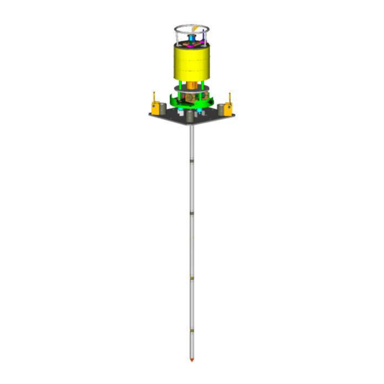
VHF radio. The piezometer can be used in "yo-yo" mode, whereby it remains connected to the coring cable, with a measurement time of a few hours, while the ship remains directly above the station. Once the measurement is made, the piezometer and its tube are retrieved by heaving the coring cable. - Page 5 33-30-077- USER GUIDE PIEZOMETRE Piezomètre_UTI UK Rev : 3 Page 5/41 Vue d'ensemble du piézomètre complet nke Tel +33 (0)2-97-36-10-12 Fax +33 (0)2-97-36-55-17 http://www.nke-nstrumentation.com PAGE 5/41...
-
Page 6: Overview And Designation
File format measure « xml » Configuration File « cfg » The logger « log » The position of the container is given by the two inclinometer mounted on the board electronic board. nke Tel +33 (0)2-97-36-10-12 Fax +33 (0)2-97-36-55-17 http://www.nke-nstrumentation.com PAGE 6/41... -
Page 7: Base Plate
In its upper part is integrated « skirt ».mounted on three « silent blocks » where the « MDS » enclosure via the two postures clamps is fixed. The « » receiving the "arrow" is assembled from beneath using the four bolts M10x30 Bulkhead nke Tel +33 (0)2-97-36-10-12 Fax +33 (0)2-97-36-55-17 http://www.nke-nstrumentation.com PAGE 7/41... -
Page 8: Lance Assembly Procedure
3.1 Lance element The lance comprises the elements described below: Bulkhead : Allows the lance to be mechanically connected to the ballast part of the piezometer. It will receive the first tube of the lance. First connecting tube: Provides the connection between the bulkhead and the first sensor sleeve. -
Page 9: Special Tools
(0.75, 1.5 and 3 m) Equipressure bladder: Allows a potential lack of oil to be compensated. 100 ml capacity. Lance tube : Final element of the piezometer lance. 3.2 Special tools Vacuum pump: Allows oil filling of the communication bus. -
Page 10: Assembly Procedure
Page 10/41 4. ASSEMBLY PROCEDURE To complete the assembly of a piezometer lance, we start from the bottom end of the lance and finish with the bulkhead, which weighs around 20 kg. To facilitate the work, arrange the sleeve numbers in the ascending order, starting from the top end of the lance. -
Page 11: Step-1 : Bottom Sleeve Assembly With Standard Tube
• Repeat steps 1, 2 and 3 as necessary When all the sleeves are assembled and only the first tube remains to be mounted: nke Tel +33 (0)2-97-36-10-12 Fax +33 (0)2-97-36-55-17 http://www.nke-nstrumentation.com PAGE 11/41... -
Page 12: Mp&Tbus - Mds Cable Assembly With Bulkhead And First Sleeve
Fit an end cannula onto the last sensor sleeve on the lance side (grease + joint) Connect the vacuum pump to this cannula (small Tygon hose) Place a clamp on the hose of the pump (not tight, close to the cannula) nke Tel +33 (0)2-97-36-10-12 Fax +33 (0)2-97-36-55-17 http://www.nke-nstrumentation.com PAGE 12/41... -
Page 13: Finalize With A Lance Tube
Grease the sensor sleeve with its 3 joints • Install à « lance tube" on it • Secure the sleeves and tubes assembly using M10 screws • Check the tightness of the screws nke Tel +33 (0)2-97-36-10-12 Fax +33 (0)2-97-36-55-17 http://www.nke-nstrumentation.com PAGE 13/41... -
Page 14: Software Winpiezo
33-30-077- USER GUIDE PIEZOMETRE Piezomètre_UTI UK Rev : 3 Page 14/41 5. SOFTWARE WINPIEZO nke Tel +33 (0)2-97-36-10-12 Fax +33 (0)2-97-36-55-17 http://www.nke-nstrumentation.com PAGE 14/41... -
Page 15: Presentation And Use
The PC and the "Piezometer" communicate through the "Communication interface". 5.2 Communication mode To communicate with the "Piezometer", the "WINPIEZO" software uses a USB RS422/RS485 serial communication port. The installation of this port must be carried out first (see § 3 page 6). -
Page 16: Installation
33-30-077- Piezomètre_UTI UK USER GUIDE PIEZOMETER Rev : 3 Page 16/41 5.3 Installation The "WINPIEZO" software does not require any particular installation. Simply copy the executable file (.exe) WINPIEZO.EXE directly onto the computer. 5.4 Install the drivers The converter contained in the "MDS communication interface" needs to be installed on your PC in order to operate. -
Page 17: Designation Of Software Com
33-30-077- Piezomètre_UTI UK USER GUIDE PIEZOMETER Rev : 3 Page 17/41 5.5 Designation of software com Opens the "Preferences" dialog box Used to configure the serial port's number and MDS communication speed Used to start the "MDS module" detection Resets the "MDS module"... -
Page 18: Overview
33-30-077- Piezomètre_UTI UK USER GUIDE PIEZOMETER Rev : 3 Page 18/41 5.6 Overview 5.7 "MDS Programming" function The "MDS programming" page allows the user to connect to the "MDS module" in order to set up and plan a measurement campaign using the various commands at his disposal. -
Page 19: Sequence Of Operating Modes For The Mds Module
33-30-077- Piezomètre_UTI UK USER GUIDE PIEZOMETER Rev : 3 Page 19/41 5.8 Sequence of operating modes for the MDS module BOOT Synchronisation de l’horloge SYNCHRONISATION Détection du bus Paramètre échantillonnages ACQUISITION Mise en route WAITING Conditions établies RECORDING Fin des conditions d’enregistrement RECORDED 5.8.1 BOOT mode... -
Page 20: Synchronization Mode
33-30-077- Piezomètre_UTI UK USER GUIDE PIEZOMETER Rev : 3 Page 20/41 5.8.2 SYNCHRONIZATION mode The command required to detect the "MP&T modules" is found under the "synchronization" mode. The "Detect sensor connected to MDS" button asks the application to find the "MP&T" modules connected to the bus. -
Page 21: Le Mode Double Cadences
33-30-077- Piezomètre_UTI UK USER GUIDE PIEZOMETER Rev : 3 Page 21/41 The "Edit MDS config" command now allows the user to set the various measurement parameters of the "MDS" sensors. The parameters are entered in a new window: Name of configuration file... -
Page 22: Acquisition Mode
33-30-077- Piezomètre_UTI UK USER GUIDE PIEZOMETER Rev : 3 Page 22/41 5.8.5 ACQUISITION Mode In Acquisition mode, a real time measurement can be performed by selecting the "Display real time measures" command. The curves of the various sensors are displayed on the graph at the selected rate. -
Page 23: Display The Data Files
33-30-077- Piezomètre_UTI UK USER GUIDE PIEZOMETER Rev : 3 Page 23/41 5.9 Display the data files The data stored on the PC can be displayed from the "MDS FILES" page. The user has various features at his disposal: "Display file config" to display data and configuration "Data chart preview"... -
Page 24: Calibration Function
33-30-077- Piezomètre_UTI UK USER GUIDE PIEZOMETER Rev : 3 Page 24/41 5.10 CALIBRATION FUNCTION To access the "MPT Calibration" function, the user must select the corresponding tab page. The application does not use the "MDS module" and communicates directly with the "MP&T"... -
Page 25: Exporting The Graph Measurements
33-30-077- Piezomètre_UTI UK USER GUIDE PIEZOMETER Rev : 3 Page 25/41 The parameters of each module detected are then collected by the software. The P&T modules are displayed in a tree structure that lists every sensor connected. To access the information relating to the "MP&T" in the tree structure, the user must first select them. -
Page 26: Communication Interface
33-30-077- Piezomètre_UTI UK USER GUIDE PIEZOMETER Rev : 3 Page 26/41 6. COMMUNICATION INTERFACE 6.1 Designation of the equipment The "Communication interface" box One A/B male/male type USB cable One 15/27 VDC power supply cord One SUBCONN cable with 8-pin female connector + locking ring L = 10m ("MP&T" link) One SUBCONN cable with 10-pin male connector + locking ring L = 10m ("MDS module"... - Page 27 33-30-077- Piezomètre_UTI UK USER GUIDE PIEZOMETER Rev : 3 Page 27/41 Piezometer operations IFREMER recommandations (33).02.97.36.10.12 Fax (33).02.97.36.55.17..http://www.nke.fr...
-
Page 28: Ship Caracteristics
33-30-077- Piezomètre_UTI UK USER GUIDE PIEZOMETER Rev : 3 Page 28/41 1.SHIP CARACTERISTICS 1.1.DECK (A frame deployment) 1. Free zone of 15 m x 4m on the deck, at the rear of the ship for A frame deployment 2. No obstacle for the launching trolley 3. -
Page 29: Lance Installation (From 6 To 15M)
1. Piezometer is rotated thanks to the launching trolley 2. The A frame is rotated and cable is paid out at low speed by the winch. 3. A stop of 10 minutes is managed as soon as the piezometer dead weight is covered by water 4. -
Page 30: Pay Out
2. Install a depressor weight (250 to 500kg), using an additional winch 3. Caracteristics: Whole weight in water less than 2,5 T Maximum length of piezometer and weight: 17m Distance between piezometer and depressor weight: 50m (33).02.97.36.10.12 Fax (33).02.97.36.55.17..http://www.nke.fr... -
Page 31: Calibration Stop
USER GUIDE PIEZOMETER Rev : 3 Page 31/41 2.3.Calibration stop calibration stop 15 minutes at more than 20m above seafloor 1. 10 mn stop when the tip of the piezometer is 20 m from the seabed. (33).02.97.36.10.12 Fax (33).02.97.36.55.17..http://www.nke.fr... -
Page 32: Lance Penetration
33-30-077- Piezomètre_UTI UK USER GUIDE PIEZOMETER Rev : 3 Page 32/41 2.4.Lance penetration Lance penetration speed 1m/s 1. Penetration speed 1m/s 2. Pay out 10m to 15m after penetration (33).02.97.36.10.12 Fax (33).02.97.36.55.17..http://www.nke.fr... -
Page 33: Verticality Control
2.5.Verticality control Verticality control. The piezometer lance is set free 1. Acoustic command 2. Piezometer dead weight release by acoustic command 3. Depressor weight keeps the cable under tension. 4. Compensation buoyancy keeps the cable above seabed. (33).02.97.36.10.12 Fax (33).02.97.36.55.17..http://www.nke.fr... -
Page 34: Dead Weight Recovery
33-30-077- Piezomètre_UTI UK USER GUIDE PIEZOMETER Rev : 3 Page 34/41 2.6.Dead weight recovery Lest retrieval 1. From dead weight in free water : speed 1m/s 2. Pay in as fast as possible 3. Depressor weight recovered on board 4. Dismount buoyancy from cable 5. -
Page 35: Lance Retrieval (From 6 To 15M)
33-30-077- Piezomètre_UTI UK USER GUIDE PIEZOMETER Rev : 3 Page 35/41 3.LANCE RETRIEVAL (FROM 6 TO 15M) 3.1.Retrieval of piezometer Pay out deep sea cable and prepare ROV Hook handle to extract piezometer The ROV dives in parallel to the pay out of the cable and hook... -
Page 36: Hook Up
33-30-077- Piezomètre_UTI UK USER GUIDE PIEZOMETER Rev : 3 Page 36/41 3.2.Hook up Cable attachment 1. ROV intervention to hook up the deep sea cable to the piezometer (33).02.97.36.10.12 Fax (33).02.97.36.55.17..http://www.nke.fr... -
Page 37: Retrieval
USER GUIDE PIEZOMETER Rev : 3 Page 37/41 3.3.Retrieval Piezometer retrieval 1. Pay in the cable at low speed 2. Necessary tension is comprised between 2 and 10 T depending on the piezometer lance length and sediment type. (33).02.97.36.10.12 Fax (33).02.97.36.55.17..http://www.nke.fr... -
Page 38: Piezometer Recovery
33-30-077- Piezomètre_UTI UK USER GUIDE PIEZOMETER Rev : 3 Page 38/41 3.4.Piezometer recovery Piezometer recovery 1. Cable is paid in at 1m/s speed 2. Necessary tension 3T (33).02.97.36.10.12 Fax (33).02.97.36.55.17..http://www.nke.fr... -
Page 39: Mode Yoyo
33-30-077- Piezomètre_UTI UK USER GUIDE PIEZOMETER Rev : 3 Page 39/41 7. 1 MODE YOYO 7.1 Gréement : 1 _ No swivel on the piezo ballast.. 2 _ 28 m of textile polyamide coaxial double-braided dia 28 mm. 3 _ Patte d'oie de 3 m et 4 m fourni par le bord. (4 m pour lest dépresseur). - Page 40 33-30-077- Piezomètre_UTI UK USER GUIDE PIEZOMETER Rev : 3 Page 40/41 33 m Benthos 15 m Ballast Piézo Base plate Tube Longueur totale sous longueur filé = 33 m + longueur pointe (33).02.97.36.10.12 Fax (33).02.97.36.55.17..http://www.nke.fr...
-
Page 41: Supporting Documents
33-30-077- Piezomètre_UTI UK USER GUIDE PIEZOMETER Rev : 3 Page 41/41 SUPPORTING DOCUMENTS 8.1 Assembly sheet Provisional sheet, see Excel file: FicheAssemblagePointeVierge.xl Piezometer lance assembly sheet Project : ERIG 3D Lance n° Date / 2012 Checker by : Time Montage...
Need help?
Do you have a question about the PIEZOMETER and is the answer not in the manual?
Questions and answers