Table of Contents
Advertisement
Available languages
Available languages
Quick Links
Advertisement
Chapters
Table of Contents

Subscribe to Our Youtube Channel
Related Manuals for VETEC WT1-B


Summary of Contents for VETEC WT1-B
- Page 1 STATIC LINE TENSIOMETER USER INSTRUCTIONS ANLEITUNG...
- Page 2 USER INSTRUCTIONS ENGLISH, V1.1 STATIC LINE TENSIOMETER WT1-B / WT2-B...
-
Page 3: Table Of Contents
Summary Thank you for purchasing Vetec’s Static Line Tensiometer Important information 1.2 YouTube video tutorials Product information 2.2 Dimensions 2.3 Technical specifications Installation and usage Installation General information Service, repair and maintenance Maintenance Waste Electrical and Electronic Equipment (WEEE) - 2 -... -
Page 4: Thank You For Purchasing Vetec's Static Line Tensiometer
1. Thank you for purchasing Vetec’s Static Line Tensiometer The Static Line Tensiometer from Vetec A/S is constructed to operate in harsh and humid environ- ments. The development focused on optimizing features that make it easy for the operator to handle the tensiometer and still achieve stable and accurate measurements. -
Page 5: Dimensions
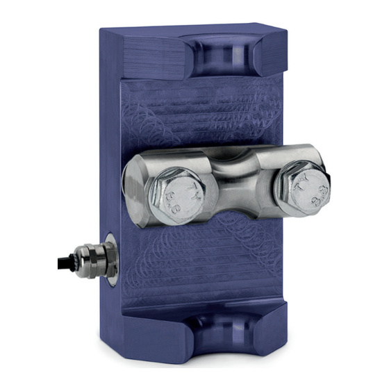
2.2 Dimensions WT1-B WT2-B Fig. 1 Fig. 2 Item no. Wire (mm) Capacity (T) Dimensions (mm) Weight (kg.) WT1-B 6-15 5T per reeving L 100 x W62 x H65 0.8 kg. WT2-B 14-28 10T per reeving L138 x W80 x H85 1.5 kg. -
Page 6: Installation And Usage
3. Installation and usage Product adjustment must only be performed by a qualifi ed technician. The user shall ensure that the operator has taken note of this instruction, usage and maintenance manual before using the Static Line Tensiometer. ”DANGER” 3.1. Installation The tensiometer is fi tted with cable gland downwards, as illustrated in fi g. - Page 7 2. Load the crane with a weight as close to the maximum load as possible, tighten the two bolts labeled as line A (fig.5) so the output signal is as close to 1.6 mV / V as possible (at a supply voltage of 10 V, it will be 16 mV. It must not exceed this). If bolts are fully tightened and 16 mV is not obtained, this is acceptable.
-
Page 8: Service, Repair And Maintenance
To prevent damage to the Tensiometer, make sure that repairs and recalibrations are carried out by qualifi ed personnel. It is recommended that recalibration and repairs are done at Vetec’s service department located in Denmark or by authorized partners. Contact Vetec’s service department for further information. - Page 9 BENUTZERANWEISUNGEN DEUTSCH, V1.1 SEILKRAFTAUFNEHMER WT1-B / WT2-B...
- Page 10 Inhaltsangabe Vielen Dank für Ihren Einkauf des Vetec Seilkraftaufnehmers Wichtige Informationen 1.2 YouTube Video-Tutorials Produktinformationen 2.2 Maße 2.3 Technische Daten Installation und Anwendung Installationsanleitung Allgemeine Informationen Wartung, Service und Reparatur Wartung und Instandhaltung Altgeräte dürfen nicht in den Hausmüll (WEEE)
-
Page 11: Vielen Dank Für Ihren Einkauf Des Vetec Seilkraftaufnehmers
1. Vielen Dank für Ihren Einkauf des Vetec Seilkraftaufnehmers Der Seilkraftaufnehmer von Vetec A/S ist für den Betrieb in rauen und feuchten Umgebungen konstruiert. Der Schwerpunkt der Entwicklung lag auf der Optimierung von Funktionen, die es dem Bediener erleichtern, den Seilkraftaufnehmer zu handhaben und dennoch stabile und genaue Messungen zu erzielen. -
Page 12: Maße
2.2 Maße WT1-B WT2-B Fig. 1 Fig. 2 Warennr. Ø Seil (mm) Kapazität (T) Maße (mm) Gewicht (kg.) WT1-B 6-15 5T pro Einscherung L 100 x W62 x H65 0.8 kg. WT2-B 14-28 10T pro Einscherung L138 x W80 x H85 1.5 kg. -
Page 13: Installation Und Anwendung
3. Installation und Anwendung Produkteinstellungen dürfen nur von einem qualifi zierten Techniker durch- geführt werden. Der Benutzer muß sicherstellen, daß der Bediener diese Gebrauchs- und Wartungsanleitung zur Kenntnis genommen hat, bevor er ”DANGER” das den Seilkraftaufnehmer verwendet. 3.1. Installationsanleitung Der Seilkraftaufnehmer wird mit der Kabelverschraubung nach unten montiert, wie in Abbildung 1+2. Stellen Sie sicher, daß... - Page 14 2. Beladen Sie den Kran mit einem Gewicht, das möglichst nahe an der Maximallast liegt, ziehen Sie die beiden mit bei Linie A gekennzeichneten Schrauben (Abb. 5) fest, sodass das Ausgangssignal möglichst nahe bei 1,6 mV/V liegt (bei einer Versorgungsspan nung von 10 V, sie beträgt sie 16 mV.
-
Page 15: Wartung Und Instandhaltung
Um Schäden am Seilkraftaufnehmer zu vermeiden, stellen Sie sicher, daß Neukalibrierungen und Reparaturen von qualifi ziertem Personal durchgeführt werden. Es wird empfohlen, die Neukalibrierung und Reparaturen von der Vetec-Serviceabteilung in Dänemark oder von autorisierten Partnern durchführen zu lassen. Für weitere Informationen wenden Sie sich bitte an die Serviceabteilung von Vetec.
Need help?
Do you have a question about the WT1-B and is the answer not in the manual?
Questions and answers