
Related Manuals for Mondial Designs Limited Sport Classic 125


Summary of Contents for Mondial Designs Limited Sport Classic 125
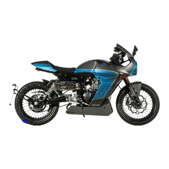
- Page 1 Sport Classic 125 Sport Classic 125 ABS Motorcycle OWNER’S MANUAL Read this manual carefully ZP682xxx before operating this vehicle...
- Page 2 PELPI INTERNATIONAL SRL as the vehicle manufacturer. WELCOME TO THE WORLD OF MONDIAL MOTORCYCLES Mondial congratulates you on choosing the Sport Classic 125 / Sport classic 125 ABS models among its range of products. We have drawn up this booklet to provide a comprehensive overview of your vehicle’s quality features.
- Page 3 Introduction Sport Classic 125 Sport Classic 125 ABS The instructions given in this manual are intended to provide a clear, easy guide to using your vehicle. It also describes routine maintenance procedures and regular checks that should be carried out on the vehicle at a Mondial Dealer or Authorized Workshop.
- Page 4 Important manual information Personal safety This is the safety alert symbols. It used to alert you to potential injury hazards. Failure to completely observe these instructions will result in serious risk of personal injury. A WARNING indicates a potentially hazardous situation which, if not avoided, could result in death, serious personal injury or property damage.
-
Page 5: Table Of Contents
Table of contents GENERAL RULES Seat Foreword Fuel tank Motorcycle care Removing and installing fairings Carbon monoxide Vehicle identification Fuel Hot components Checks Coolant Fuel tank cap Front fork adjustment Engine oil and gearbox oil used. Brake fluid Clutch lever adjustment Battery hydrogen gas and electrolyte Running in Side stand... - Page 6 Tool kit equipment Charging the battery Electrical wiring diagram (Sport Classic 125) Extended periods of inactivity Electrical wiring diagram ( Sport Classic 125 ABS PERIODIC MAINTENANCE AND ADJUSTMENT Fuses To check fuse Schedule maintenance table (Sport Classic 125) To check fuse...
-
Page 7: General Rules
Chapter 01 Sport Classic 125 GENERAL RULES Sport Classic 125 ABS absABS ENERAL RULES... -
Page 8: Foreword
General rules Foreword NOTE Carry out maintenance operations at half the intervals specified if the vehicle is used rainy or dust conditions, off road or for track use. Motorcycle care Mondial recommends using quality products to clean the vehicle. The use of unsuitable products can damage vehicle components. For cleaning do not use solvents such as”... - Page 9 General rules Cleaning of sensitive parts BODYWORK To keep the motorcycle bright, wash it regularly, especially if used in areas with elevated levels of pollution or mud. Aggressive stains from tree resins, gasoline, oil, brake fluid or bird excrement in general must be removed immediately, otherwise permanent stains on the paint can appear.
-
Page 10: Carbon Monoxide
General Rules Carbon monoxide All engine exhaust contains carbon monoxide, a deadly gas. If you need to keep the engine running to perform a procedure, please ensure that you do so in an undeveloped area or very well-ventilated. Never let the engine run in an enclosed area. If you do work in a closed area, make sure to use a smoke extraction system. -
Page 11: Hot Components
General rules • Avoid spilling fuel off the filler cap as it may catch fire in contact with the engine hot surfaces. In case of accidental fuel spills, check that the area is completely dry before starting the vehicle. Fuel expands when exposed to heat or sun rays, therefore be careful and do not overfill the fuel tank. Stop filling when the fuel reaches the bottom of filler tube. -
Page 12: Engine Oil And Gearbox Oil Used
General Rules Engine oil and gearbox oil used. CAUTION It is advisable to wear protective impermeable gloves when servicing the vehicle. The engine or gearbox oil may cause serious injuries to the skin if handled for prolonged periods of time and on a regular basis. -
Page 13: Battery Hydrogen Gas And Electrolyte
General rules Battery hydrogen gas and electrolyte The battery electrolyte is toxic, corrosive and it contains sulfuric acid, it can cause burns when is in contact with the skin while handling battery electrolyte, wear tight fitting gloves and protective apparel. In the event of skin contact with the electrolyte fluid, rinse well with plenty of clean water. -
Page 14: Vehicle
Chapter 02 Sport Classic 125 VEHICLE Sport Classic 125 ABS absABS... -
Page 15: Arrangement Of The Main Components
Vehicle Sport Classic 125 / Sport classic 125 ABS Arrangement of the main components Left view Fr. Brake disc Swingarm Fr. Fork assy., Chain assy., Fr. Fender Passenger footrest [left] (Snap-on, closed/open ECU (Engine Control Unit)/Throttle boby Rider footrest [left] Fr. - Page 16 Vehicle Sport Classic 125 / Sport Classic 125 ABS Arrangement of the main components Right view Rear Caliper assy., Fr. Flasher light (right) License light assy., Oil drain plug Rear shock absorber (right) ABS control unit (only ABS Model) Silencer assy., Pedal brake Seat lock assy.,...
- Page 17 Vehicle Sport Classic 125 / Sport Classic 125 ABS Arrangement of the main components Rear view / Front view 9 10 Rear view mirror (left) Engine stop switch Clutch lever Start switch button Horn button Rear flasher light (left) Rear flasher light (right) Dimmer switch Taillight unit assy.,...
-
Page 18: Analog Instrument Panel (Symbols Functions)
Vehicle Analog instrument panel (function of symbols) Neutral indicator light "N 5. Turn signal indicator light 2. Oil pressure warning light 6. High beam indicator light 3. Engine trouble warning light Function switch button 4. LCD Clock screen ABS light (only ABS Model) “... - Page 19 Vehicle Hi-beam indicator light This blue indicator light comes on when the high beam of the headlight is switched on. Function switch button : This button is used to select the different settings of the multi-functions meter unit. “ABS” trouble warning light (only for ABS model) This indicator light comes on if a problem is detected.
-
Page 20: Instrument Display (Multifunction Display)
Vehicle Multi-function display 1. Digital speedometer 2. Digital tachometer 3. Multifunction digital display: ODO/TRIP/ rpm etc. 4. Clock 5. Fuel meter 6. Coolant temperature meter 7. Side stand lowered warning signal (* No function) 8. Transmission gear display These vehicles do not have this function, only the instrument got this display configuration. -
Page 21: Multi-Function Meter Operations
Vehicle Multi-function meter operations Instant speed display The speed is displayed always by three digital digits in the center of the display, regardless of the function selected or alarm indication that is active. The information can be viewed in km/h or MPH, depending on how the setup menu is configured. - Page 22 Vehicle ODO/ TRIP / rpm display Odometer function (ODO The odometer function is selected by pressing the set-up button till when the ODO is displayed on the right-hand side of the screen. In the ODO function, the total distance covered by the machine is displayed. This distance is expressed in kilometers or miles, depending on the unit of measure that it has been selected as configuration.
- Page 23 Vehicle Tachometer digital display function [ODO>TRIP > rpm] This rpm function is selected by pressing the set-up button when the rpm is displayed on the right side of the screen. The tachometer revolutions are expressed in rpm /1000. The tachometer shows engine speed in crankshaft revolutions per minutes r/min).
- Page 24 Vehicle Fuel Meter The display segments of the fuel meter show the fuel levels. When only one segment is left near “E” (Empty), the fuel level warning light comes on, then refuel as soon as possible. 1. Fuel level warning light 2.
-
Page 25: Set-Up Configuration
Vehicle Transmission gear display The transmission gear shows the selected gear. When the gear is engaged in Neutral position, no indication appears on the display, while the green N signal light (2) coming on. Set-up configuration You can enter the configuration menu only when the vehicle is stopped. Clock set In ODO mode, press and hold the function button for about 5 sec. -
Page 26: Ignition Switch / Steering Lock
Vehicle Ignition switch The ignition switch is located on the handle crown. NOTE: • The key activates the ignition switch/steering lock, the fuel tank cap and the seat lock. • Two keys are supplied with the vehicle (a spare one). LOCK (1): The steering is locked. -
Page 27: Horn Button
Vehicle Horn button Press it to sound the horn. Turn signal switch Move the switch to the left, to signal a left turn; move the switch to the right to signal a right turn. Pressing the switch deactivates the turn indicator. CAUTION If the warning light with arrows flashes quickly, it means that one or more turn indicator light bulbs burned out. -
Page 28: Engine Stop Switch
Vehicle Engine stop switch Set this switch to “ ” before starting the engine. Set this switch to case of emergency, such as when the vehicle overturns or when the throttle cable is stuck. Start switch ” When the engine stop button is on “ , by pressing the button starting motor makes the engine spins. -
Page 29: Seat
Vehicle Seat Seat removal To Remove the seat, operate as follows: Position the vehicle on the stand. Unscrew bolt (1) and washer (2) on both sides. Enlarge the front sides of tail cover then, remove it. Insert the ignition key in the seat lock [A] and turn it clockwise. Move the seat [B] backward while lifting-up the rear part of seat. - Page 30 Vehicle Seat installation To install the seat, proceed in reverse order to the removal operation: Fit the hook portion [A] into the slop of fuel tank [B]. Slip the seat hook [C] in the stay seat lock [D]. Press the seat down, making the slot snaps. Reassemble the tail cover spreading it outwards then, lock it with the bolts and washers(1) and (2) on both sides.
-
Page 31: Fuel Tank
Vehicle Fuel tank Fire hazard. Allow engine and exhaust silencer to cool off. Fuel vapors are harmful to health. Before any operation, make sure that the room when you are working has adequate air ventilation. Do not inhale fuel vapors. Do not smoke or use naked flames. - Page 32 Vehicle 5. Remove the front cowling following the next operations: a) Unscrew the upper bolt [E] and lower bolt [F] on both sides of the front cowling b. Unscrew bolts and remove both the rear-view mirrors and its locating dampers [G] on both sides. c.
- Page 33 Vehicle d. Disconnect the headlight bulb holder[L] and the position light connection [M] then, slip out the front cowling with headlight assembled. 6. Open the tank cap and remove the 4 fixing bolts [N].
- Page 34 Vehicle 7. Remove upper bolt [O] of the fuel tank cover. 8. Remove the lower bolt [P] of the tank cover and lift the central band [Q] and the fuel tank cap at the same time Remove the upper fixing radiator screw [R] on both sides. 10.
- Page 35 Vehicle 11. Remove the tank cover upwards and towards the rear of the vehicle. CAUTION Be careful not to hit other body parts with the sideward fairings lower brackets to avoid damage. Fuel tank removal < Remove: • Clip [A] •...
- Page 36 Vehicle CAUTION Handle with care. Do not force the fuel pipe and the pump connector cable (1) when lifting the fuel tank. When lowering the tank, take care not to press: • The fuel pipes, because it could cause fuel spills. •...
-
Page 37: Removing And Installing Fairings
Vehicle Removing and installing fairings The cowlings and panels shown need to be removed to perform some of the maintenance jobs. Refer to this section each time a cowling or panel needs to be removed and installed. Lower panel assy.,(A) Lower panel assy., (A) Cowling, 2 Cowling, 1... - Page 38 Vehicle Lower panel (A) Lower panel removal To remove the lower panel, unscrew the bolts [A] on both sides and take out the panels assembled. Lower panel installation Place the lower panel in its original position, then secure it with the bolts [A]. Cowling,1 (B) Cowling removal To take out the cowling 1, operate as follows:...
- Page 39 Vehicle 6. Remove all the bolts [E] 7. Remove bolt [F] and take out the cowling 1. < F < E < Cowling installation To reinstall the cowling 1, place the cowling in the original position and proceed following the reverse order of the removal procedures, taking care to use a new vinyl clamp to fix the connection of flasher lights wires and to pay attention to insert the cowling's projections [G] into the lateral slots of the front <...
- Page 40 Vehicle Cowling,2 (E) Cowling removal To disassemble the cowling 2, follow the same steps from 1 to > 5 explained in how to remove the cowling 1 then, 6. Remove the upper bolt [E] < F 7. Remove the lower cowling bolt [F] <...
- Page 41 Vehicle Front cowling (upper), (C) NOTE: Regarding disassembling and reassembling of the front cowling, please refer to the point (5) of fuel tank cover removal chapter (page 31-32). Tail cover, (D) NOTE: Regarding the tail cover removal, please refer to the seat removal (page 28).
- Page 42 Vehicle 3. Remove bolts [A] with washers. 4. Pull the side cover [C] evenly outward to get it out of mushroom [B] and remove it. Remove the screws [A] and separate the cover from side cover [B] as necessary. Side covers installation To reinstall the side cover: •...
- Page 43 Vehicle Tool kit compartment The tool kit compartment is located under the seat. To reach it: • Remove the seat (see seat removal to page 28) NOTE If you do not have the tools or experience required for a particular job, have an Official Mondial dealer to perform it for you.
-
Page 44: Vehicle Identification
Vehicle Vehicle Identification Write down the chassis and engine number in the specific space of this booklet. The chassis number is handy when purchasing spare parts. CAUTION The identification codes modification is a serious punishable crime. In addition, the limited warranty for new vehicles will be void if the vehicle identification number (VIN) has been modified or not prompt determined. -
Page 45: Use
Chapter 03 Sport Classic 125 Sport Classic 125 ABS ENERAL RULES... -
Page 46: Checks
Checks In case of battery failure or a bump-start, the correct operation of the vehicle and the respect for the regulations in force are not guaranteed. CAUTION Before setting-off, always carry out a preliminary check of vehicle, for correct and safe operation. Failure to do, so may lead to severe personal injury or vehicle damage. - Page 47 ITEM CHECKS PAGE • Front and Rear brake Check for proper operation. • If soft or spongy, have a Mondial dealer bleed hydraulic system. • Check brake pads for wear. • Replace if necessary. • Check fluid level in reservoir. •...
- Page 48 ITEM CHECKS PAGE • ……. Make sure that all nuts, bolts and screws are properly tightened. Chassis fasteners • Tighten if necessary. • Check chain slack and adjust if necessary Drive chain • 85-88 Check chain condition and lubricate if necessary. •...
-
Page 49: Fuel Tank Cap
Fuel tank cap The fuel tank cap is fitted with a lock. To open it: 1. Lift the lock protection (1) 2. Insert the key (2) and turn it clockwise. To lock it: 1. Keep turn the key (2) and push the cap (3) down. 2. -
Page 50: Clutch Lever Adjustment
Clutch lever adjustment Adjust the clutch lever when the engine stops, or the vehicle tends to move forward even when clutch lever is operated, and the gear engaged, or if the clutch” slides”, resulting in acceleration delay considering the engine revs. Check the lever free play: <... -
Page 51: Running In
Read the Owner’s Manual carefully to become familiar with all controls. If there is a control or function you do not understand, ask your Mondial dealer Failure to master yourself with the controls can lead to loss of control, which cause an accident or injury. Running-in Running-in is essential to ensure the durability of the vehicle. -
Page 52: Starting Up The Engine
Starting up the engine In case of battery failure or a bump start, the correct operation of vehicle and the regulation respect in force are not guaranteed. • Exhaust fumes contain carbon monoxide, an extremely harmful substance if inhaled. • Never start the engine in a closed or insufficiently ventilated space. - Page 53 ” ”. 3. Make sure the light switch (1) is set to the low beam light position 4. Turn the key (2) and set the ignition switch to “ “. At this stage, a self-diagnosis is detected: 5. All function of the multifunction display is checked two seconds by itself. 6.
- Page 54 8. Block at least one wheel by operating one brake lever. 9. Pull the clutch lever (6) completely, set the shift pedal (7) to neutral gear and the green”N” indicator light (8) lights up. 10. Push the start button (9). 11.
-
Page 55: Moving Off / Riding
Do not set off suddenly when engine is cold. Ride at low speed for several kilometers, this will allow the engine to warm up and reduce polluting emissions and fuel consumption. If the engine trouble warning light (10) is on during regular engine operation, this means that the engine control unit has detected a problem. - Page 56 1. With the throttle grip (1) released (Pos. A) and the engine idling, fully operate the clutch lever (2). 2. Engage first gear by pushing the shift pedal (3) down. 3. Release the brake lever (pressed during start-up). CAUTION When turning off the vehicle, do not release clutch too quickly or suddenly, this could cause the engine stop or lift the rear wheel of the vehicle.
- Page 57 To engage the second gear: Ride with the correct gear and to right speed for road conditions. Do not operate engine at too low rpm level. 1. Release the throttle grip (1) [ Pos. A], operate the clutch lever (2) and lift the shift pedal (3). Release the clutch lever (2) 2.
- Page 58 The shifting from a higher to a lower gear, called “downshift” is carried out: 1. When riding downhill and when braking to increase the braking power by using engine brake. 2. When going uphill, when the engaged gear does not suit the speed (high gear, moderate speed) and the number of engine revs fall.
- Page 59 • Operating only either the front or the rear brake, the braking power is significantly reducing, and wheel may get blocked resulting in the lack of grip. • When stopping while travelling uphill, close the throttle completely and only use the brakes to hold vehicle on position.
-
Page 60: Engine Stop
Engine stop • Release the throttle grip (Pos. A), brake gradually and simultaneously downshift to slow down. Once the speed is reduced and before stopping the vehicle, operate the clutch lever so that the engine does not shut off. When the vehicle is at a standstill: •... -
Page 61: Parking
Parking It is very important to select an adequate parking spot, in compliance with road signals and the guidelines described below: CAUTION • Park on safe and flat ground to prevent the vehicle falls. • Do not lean the vehicle against a wall or lay it on the ground. •... -
Page 62: Catalytic Converter
Catalytic converter The vehicle has a silencer with a ” platinum - palladium - rhodium three-way ” metal catalytic converter. This device oxidises the CO (carbon monoxide) producing carbon dioxide, and the UHC (unburned hydrocarbons) producing water vapour and reduces NOX (nitrogen oxide) producing oxygen and nitrogen present in the exhaust fumes. •... -
Page 63: Side Stand
Side Stand 1. Grasp the grab bar [1] (under the seat) from left side. CAUTION • Risk of falling or rolling over. • Make sure your vehicle stable. 2. Push the side stand with your right foot [2] to fully extend the stand. 3. - Page 64 NEVER leave the ignition key in the lock and always use the steering lock. Park the vehicle in a safe place such as a garage or a place with police. Whenever possible, use an additional anti-theft device. Make sure all vehicle documents are in order and the road tax paid.
-
Page 65: Maintenance
Chapter 04 Sport Classic 125 MAINTENANCE Sport Classic 125 ABS... -
Page 66: Engine Oil Level Check
Maintenance Engine oil level check Check the engine oil level frequently. NOTE Carry out maintenance operations at half the intervals specified if the vehicle is used rainy or dust conditions, off road or for track use. • Engine oil level must be checked when the engine is warm. •... -
Page 67: Engine Oil Topping-Up
Maintenance • Unscrew and remove the oil level dipstick again and check that the engine oil level is guaranteed between the two reference marks: MAX = maximum level. MIN = minimum level • The oil level is correct when it is close to the” MAX” reference. •... -
Page 68: Engine Oil Change
Maintenance Engine oil change CAUTION To change the engine oil, please contact an official Mondial dealer. If you are adequately trained and experienced, refer to the instructions in the workshop booklet available also at any dealer. Engine oil filter replacement CAUTION To remove and clean the engine oil filter, please contact an official Mondial dealer. -
Page 69: Tires
Maintenance Tires • Check tire inflation pressure regularly at room temperature. • Measurements may be incorrect if tires are warm. • Check pressure mainly before and after long trips. • If the tire pressure is too high, unevenness in the road surface will not be cushioned and will be transmitted to the handlebar, resulting in an unpleasantly harsh ride and poor road holding, especially when cornering. -
Page 70: Spark Plug
Maintenance MINIMUM TREAD DEPTH Front: 2 mm (0.078 in) Rear: 2 mm (0.078 in) Tire size and air pressure (measured on cold tires): Front size (where applicable for approvals): 100/80-17 52H or 110/80-17 57H Pressure front (only rider) [up to 90 kg - 198 lb.]: 190kPa (1,93kgf / cm 27,5 psi) Pressure front (rider + passenger):... - Page 71 Maintenance • Replace the spark plug if there are cracks on its insulating material, corroded electrodes or large deposits. • Check the electrode gap with a thickness gauge. This gap should be 0.5 (0.02 in); adjust it if required by carefully bending the earth electrode.
-
Page 72: Removing The Air Filter
Maintenance Removing the air filter 1. Remove tail cover and seat (see page 28). 2. Undo and remove the four screws (1) 3. Lift the filter box cover (3) and slide it together with the filtering element (4). 4. Separate the filtering element (4) on the clean and dry surface of the filter box cover (3). -
Page 73: Air Filter Replacement
Maintenance CAUTION When cleaning the air filter element, make sure it is not damage. If it is damaged, replace it. • Clean the inner side of the air filter (2) with a clean cloth. • Clean the inlet duct (3). Air filter replacement CAUTION Never reuse an old air filter element. -
Page 74: Coolant Level Check
Maintenance CAUTION • Do not remove the coolant reservoir cap when engine is hot, since coolant is under pressure and very hot. • Wait for engine cooled down, before checking or topping up coolant level. Coolant level check • Shut off the engine and wait until it cools off. CAUTION Park the motorcycle on safe and level surface. -
Page 75: Coolant Fill In
Maintenance Coolant fill in Once the check is performed, if necessary add coolant; proceed as follow: 1. Remove the coolant reservoir cap. 2. Wait a few seconds so that any pressure in the system is purged. CAUTION Coolant is toxic if ingested and in contact with your eyes or skin may cause irritation. -
Page 76: Checking The Brake Fluid Level
Maintenance Checking the brake fluid level NOTE Min. Park the motorcycle on safe and level surface. CAUTION Risk or falling or rolling over. When holding the vehicle upright, from parking to ride position, the side stand automatically folds up. Front brake 1. -
Page 77: Changing The Brake Fluid
Maintenance Changing the brake fluid CAUTION These operations are complicated and risky. Contact an official Mondial dealer to perform these operations. If you are adequately trained and experienced, refer to the instructions in the workshop booklet available also at any official Mondial dealer. -
Page 78: Use A New Battery
Maintenance Use of a new battery First Disconnect: • Make sure that the ignition switch is set to • Remove the seat (see page 28) • Remove the battery band. • Disconnect the negative lead ( ) at first and then, the positive one ( •... -
Page 79: Extended Periods Of Inactivity
Maintenance Extended periods of inactivity If the vehicle is not used for more than fifteen days, it is necessary to recharge the battery to avoid sulphating: • Remove the battery and put it away in a cool and dry place. In wintertime or when the vehicle is out of use for prolonged periods, check charge level frequently (about once a month) to prevent deterioration. -
Page 80: To Check Fuse (Sport Classic 125)
Maintenance To check fuse( only for Sport Classic 125) : First check the secondary 20A fuse (2) and then, the main 30A fuse (1). • To avoid an accidental short circuit, set the ignition switch to • Before replacing the fuse, find and solve, whenever possible, the problem that caused it the blow. -
Page 81: To Check Fuse (Sport Classic 125 Abs)
Maintenance To check fuse ( only Sport Classic 125 ABS ) : First check the secondary 20A fuse (2) and then, the main 30A fuse (1). • To avoid an accidental short circuit, set the ignition switch to • Open the fuse box by pressing the release button (A) •... -
Page 82: Lamps
Maintenance Lamps Headlight bulbs replacement • Rest the vehicle on its stand. NOTE Before changing a bulb, check the fuse. In the headlight, there are: • A headlight bulb ( high / low beam light bulb) [B] - (12V-35/35W). • A position light bulb [C] (12V-5W) To replace the headlight bulbs: CAUTION... - Page 83 Maintenance Replacing the auxiliary light bulb To replace the auxiliary light bulb, proceed as follows: 1. Disconnect the position light connection [M] then, slip out the front cowling (refer to point (5) page 31) with headlight assembled. 2. Remove the 4 bolts [A] that fix the headlight support to the front cowling. 3.
-
Page 84: Headlight Adjustment
Maintenance Headlight adjustment For a quick check of the correct direction of the front light beams, place the vehicle ten meters from a vertical wall and make sure the ground is level. Turn on the low beam light “ ”, sit on the motorcycle and check that the light beam projected to the wall is slightly below horizontal straight line (about 9/10 of the total height). -
Page 85: Rear Turn Signal Lights
Maintenance Rear turn signal lights • Rest the vehicle on its stand. • Loosen and remove screw (1). • Remove the turn signal light lens (2). • Press bulb (3) slightly and turn it counterclockwise. • Pull the bulb (3) out of its seat. •... -
Page 86: Replacing The License Plate Light Bulb (Type A)
Maintenance Replacing the license plate light bulb (Type A) License Plate (Type A) To replace the license plate light bulb: • Rest the vehicle on its stand. • Unscrews and remove bolts [A] • Remove the license plate group [B]. •... -
Page 87: Replacing The License Plate Light Bulb (Type B)
Maintenance Replacing the license plate light bulb (Type B) License Plate (Type B) License plate (type B) To replace the license plate light bulb: • Rest the vehicle on its stand. • Pull out the socket license plate light [A] •... -
Page 88: Front Turn Signal Lights
Maintenance Front turn signal lights • Rest the vehicle on its stand. • Loosen and remove screw (1). • Remove the turn signal light lens (2). • Press bulb (3) slightly and turn it counterclockwise. • Pull the bulb (3) out of its seat. •... -
Page 89: Front And Rear Brake
Maintenance • If necessary adjust the position of the rear-view mirrors, as shown in the figure, in a properly way. CAUTION Do not move the mirror arms (1) up and down to avoid any loosening while driving. CAUTION It is strictly forbidden to remove the rear-view mirrors for riding on the road. - Page 90 Maintenance NOTE The following information refers to one braking circuit, but it is valid for both circuits. Wear of brake pads depends on the use, by riding style and the roads. CAUTION Check brake pads for wear, mainly before each ride. <...
-
Page 91: Periods Of Inactivity
Maintenance Periods of inactivity Take some precautions to avoid problems caused by not using the vehicle. Also, carry out general maintenance and checks before garaging the vehicle so, one can forget to do so afterwards. Proceed as follows: • Remove the battery. •... - Page 92 Maintenance • Always clean off any smog and pollution residue, tar stains, insects, bird droppings, etc., from the bodywork. • Avoid parking the vehicle under trees. During some seasons, resins, fruits or leaves containing aggressive chemical substances may damage the paintwork, when they fall from trees. •...
- Page 93 Maintenance To clean the headlights, use a sponge soaked in water and mild detergent, rubbing the surface gently and rinsing frequently with plenty of water. Remember to clean the vehicle carefully before applying silicon wax polish. Do not polish matt-painted surfaces with polishing paste. The vehicle should never be washed on direct sunlight, especially during summer, or with the bodywork still hot as the car shampoo can damage the paintwork if it dries before being rinsed off.
-
Page 94: Transport
Maintenance After washing lubricate the following components: • drive chain. • lever controls. • pedal controls. • clutch cable. Transport NOTE • Before transporting the vehicle, it is necessary to empty the fuel tank and the fuel system adequately, checking that they are dry. •... -
Page 95: Drive Chain Slack Check
Maintenance • Excessive loosening of the chain may cause noise or knocking resulting in chain pad and guide plate wear. • Check the chain clearance on a regular basis and adjust it, if necessary. • To change the chain, take your vehicle to a Mondial official dealer that will provide accurate and prompt service. -
Page 96: Drive Chain Slack Adjustment
Maintenance CAUTION If the clearance is greater in some positions, this means that some chain links are flattened or jammed. To avoid risk of seizure, lubricate the chain on a regular basis. Adjust the clearance if it is uniform but over or below 25~30mm(0.98~1.18 in). CAUTION To guarantee perfect efficiency and maximum duration of the final drive elements, never exceed the chain tensioning indications... -
Page 97: Checking Wear Of Chain, Front And Rear Sprockets
Maintenance Checking wear of chain, front and rear sprockets. Also check the following parts and verify that the chain, the pinion and the driven sprocket do not have: • Damaged rollers. • Loosened pins. • Dry, rusty, flattened or jammed chain links. •... -
Page 98: Chain Lubrication And Cleaning
Maintenance Chain lubrication and cleaning CAUTION Please be very careful when adjusting, lubricating, and replacing the chain. Lubricate the chain whenever necessary and, at least, every 500 km (310.68 mi), and always after washing the vehicle or riding in the rain. Do not wash the chain with water jets, vapor jets, high-pressure water jets and highly flammable solvents. -
Page 99: Technical Data
Chapter 05 Sport Classic 125 TECHNICAL DATA Sport Classic 125 ABS... - Page 100 Technical Data Dimension Overall length: 2040 mm Overall width: 757 mm Overall height: 1152 mm Seat height: 800 mm Wheelbase: 1360 mm Ground clearance: 143 mm Carb weight: 133 kg Weight (without fuel): 123 kg Engine Engine type: Liquid cooled, 4stroke, DOHC, 4 valves Cylinder arrangement: Single cylinder Displacement:...
- Page 101 Technical Data Capacity Fuel tank: 9.5 +/- 0.3 L. Engine oil: 1115 cm (0.3 US gal) Coolant reservoir capacity : 0.33 L Coolant reservoir : 0.18 L (from minimum level up to the maximum level mark) Seats (capacity): Vehicle maximum load (rider +passenger + luggage) 167 kg (368 lb.) Transmission Type:...
- Page 102 Technical Data Fuel system Fuel recommended: Regular unleaded gasoline (Gasohol [E5] acceptable) Chassis Chassis type: Semi-double crate Suspensions Front suspension: Up-side down fork Front wheel travel: 90 mm (3.5in) Rear shock absorber: Hydraulic shock absorber x 2 Rear wheel travel: 120 mm (2.75 in) Brakes Φ280 mm (11.02 in)
- Page 103 Technical Data Tires Front - size (where applicable for approvals): 100/80-17 52 H or 110/80-17 57H Pressure front (only rider) [up to 90 kg - 198 lb.]: 190kPa (1,93kgf / cm 27,5 psi) Pressure front (rider + passenger): 200kPa (2,0kgf / cm , 29 psi) Rear size (where applicable for approvals): 130/70-17 62H or 140/70-17 66H...
-
Page 104: Tool Kit Equipment
Technical Data Main Fuse 30A (Battery recharge) Secondary Fuse 20A (ECU, Position light , headlight relay,headlight unit assy.,) Auxiliary Fuse: (Sport Classic 2A (ABS starting) 125 ABS) Fuse: (Sport Classic 10A (ABS Control unit) 125 ABS) Fuse: (Sport Classic 15A (ABS motor) 125 ABS) Bulbs HS1 - 12V –... -
Page 105: Electrical Wiring Diagram (Sport Classic 125)
Technical Data Sport Classic 125: Electrical wiring diagram... -
Page 106: Electrical Wiring Diagram ( Sport Classic 125 Abs )
Technical Data Sport Classic 125 ABS: Electrical wiring diagram... -
Page 107: Periodic Maintenance And Adjustment
Chapter 06 Sport Classic 125 PERIODIC MAINTENANCE Sport Classic 125 ABS AND ADJUSTMENT... -
Page 108: Schedule Maintenance Table
Periodic Maintenance and Adjustment Scheduled maintenance table • Correct maintenance is fundamental for ensuring long life of your vehicle and maintaining optimum function and performance. • To this end, PELPI-MONDIAL offers a set of checks and maintenance services (at the owner’s expense), that are summarized in the table shown on the following page. - Page 109 Periodic Maintenance and Adjustment Scheduled maintenance table Performed Related to ITEM REQUIRED WORK ODOMETER READING by Dealer emission x 1000 km control 11.1 14.9 x 1000 mi. • Perform dynamic inspection using Mondial suggested diagnostic tool (SC125 only) • ...
- Page 110 Periodic Maintenance and Adjustment Scheduled maintenance table Performed Related to ITEM REQUIRED WORK ODOMETER READING by Dealer emission x 1000 km control 11.1 14.9 x 1000 mi. • Check for coolant level and vehicle for coolant leakage.
- Page 111 Periodic Maintenance and Adjustment Scheduled maintenance table Performed Related to ITEM REQUIRED WORK ODOMETER READING by Dealer emission x 1000 km control 11.1 14.9 x 1000 mi. • Wheel bearings Every 2 years Check bearings for looseness or damage. ...
- Page 112 Periodic Maintenance and Adjustment Scheduled maintenance table Performed Related to ITEM REQUIRED WORK ODOMETER READING by Dealer emission x 1000 km control 11.1 14.9 x 1000 mi. • Moving parts and cables Lubricate. • Check operation. •...
-
Page 113: Table Of Recommended Products
Periodic Maintenance and Adjustment Table of recommended products CAUTION • Brake fluid: use new brake fluid only. Do not mix varied brands or types of oil without checking their base compatibility. • Coolant: use only antifreeze solutions and corrosion inhibitors without nitrite that ensure a protection up to at least (-35℃) (-31℃). -
Page 114: Handover Inspection
Handover inspection... -
Page 115: Confirmation Inspection
Confirmation-Inspection... - Page 116 Confirmation-Inspection...
- Page 117 THE VALUE OF SERVICE Because of continuous updates and specific technical training programs for PELPI international products, only PELPI Official Network mechanics know this vehicle fully and have the specific tools necessary to carry out maintenance and repair operations correctly. The reliability of the vehicle also depends on its mechanical conditions.
- Page 118 Sport Classic125 Sport Classic 125 ABS Sport Classic 125 Sport Classic 125 ABS Owner’s manual @PELPI International Srl. . Edition, August 2019 All right reserved...
Need help?
Do you have a question about the Sport Classic 125 and is the answer not in the manual?
Questions and answers