Lennox MERIT ML195UH Installation Instructions Manual
Gas furnace upflow / horizontal air discharge
Hide thumbs
Also See for MERIT ML195UH:
- Installation instructions manual (56 pages) ,
- User's information manual (7 pages) ,
- User's information manual (8 pages)
Table of Contents
Advertisement
Quick Links
© 2019 Lennox Industries Inc.
Dallas, Texas USA
Contents
Unit Dimensions - inches (mm) ......................................2
ML195UH Gas Furnace..................................................3
Shipping and Packing List ..............................................3
Safety Information ..........................................................3
Use of Furnace as Construction Heater .........................4
General ...........................................................................5
Combustion, Dilution & Ventilation Air ............................5
Installation - Setting Equipment ......................................8
Filters ............................................................................13
Duct System .................................................................13
Pipe Fittings Specifications...........................................13
Joint Cementing Procedure ..........................................15
Venting Practices ..........................................................16
INSTALLATION
INSTRUCTIONS
ML195UH
MERIT
SERIES GAS FURNACE
®
UPFLOW / HORIZONTAL AIR DISCHARGE
507268-03
02/2019
Supersedes 07/2018
THIS MANUAL MUST BE LEFT WITH THE
HOMEOWNER FOR FUTURE REFERENCE
This is a safety alert symbol and should never be
ignored. When you see this symbol on labels or in man-
uals, be alert to the potential for personal injury or death.
As with any mechanical equipment, contact with sharp
sheet metal edges can result in personal injury. Take
care while handling this equipment and wear gloves and
protective clothing.
Improper installation, adjustment, alteration, service
or maintenance can cause property damage, personal
injury or loss of life. Installation and service must be
performed by a licensed professional HVAC installer or
equivalent, service agency, or the gas supplier.
Vent Piping Guidlines ...................................................17
Gas Piping ....................................................................35
Electrical .......................................................................38
Unit Start-Up .................................................................41
Gas Pressure Adjustment .............................................42
Proper Cumbustion.......................................................43
High Altitude Information ..............................................43
Testing for Venting and Combustion Air........................44
Repair Parts List ...........................................................44
Other Unit Adjustments.................................................45
Service..........................................................................46
Twinning ......................................................................47
Start-Up & Performance Check List .............................48
Page 1
CAUTION
WARNING
Advertisement
Table of Contents

Subscribe to Our Youtube Channel
Related Manuals for Lennox MERIT ML195UH


Summary of Contents for Lennox MERIT ML195UH
-
Page 1: Table Of Contents
INSTALLATION INSTRUCTIONS ML195UH © 2019 Lennox Industries Inc. Dallas, Texas USA MERIT SERIES GAS FURNACE ® UPFLOW / HORIZONTAL AIR DISCHARGE 507268-03 02/2019 Supersedes 07/2018 THIS MANUAL MUST BE LEFT WITH THE HOMEOWNER FOR FUTURE REFERENCE This is a safety alert symbol and should never be ignored. -
Page 2: Unit Dimensions - Inches (Mm)
Unit Dimensions - inches (mm) EXHAUST AIR 3-3/8 NOTE - 60C size units that require air volumes OUTLET (86) over 1800 cfm must have one of the following: 1. Single side return air with transition, to accommodate 2 (51) 20 x 25 x 1 in. cleanable air filter. Required to maintain proper air velocity. -
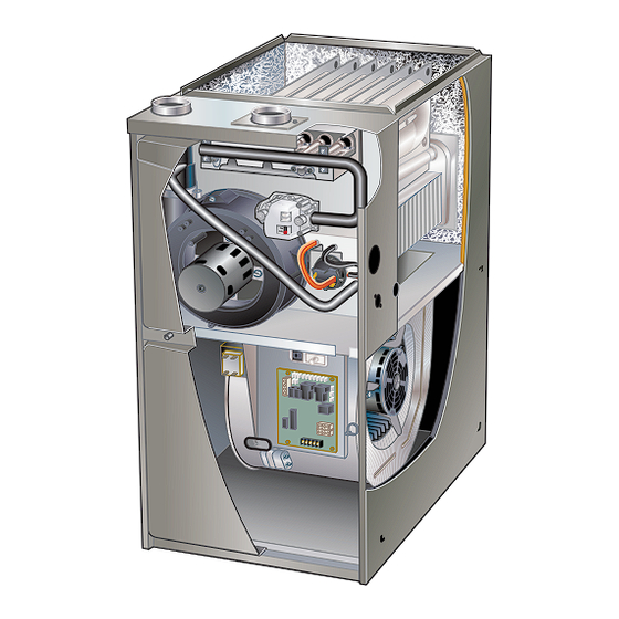
Page 3: Ml195Uh Gas Furnace
ML195UH Gas Furnace Shipping and Packing List The ML195UH Category IV gas furnace is shipped ready Package 1 of 1 contains for installation in the upflow or horizontal position. The fur- 1 - Assembled ML195UH unit nace is shipped with the bottom panel in place. The bot- 1 - Bag assembly containing the following: tom panel must be removed if the unit is to be installed in horizontal or upflow applications with bottom return air. -
Page 4: Use Of Furnace As Construction Heater
American National Standards Institute, Inc. In Canada, all electrical wiring and grounding for the unit must be installed according to the current regulations of 11 West 42nd Street the Canadian Electrical Code Part I (CSA Standard C22.1) New York, NY 10036 and/or local codes. -
Page 5: General
Water softening chemicals FAILURE TO FOLLOW THE ABOVE INSTALLATION IN- STRUCTIONS VOIDS THE MANUFACTURER’S EQUIP- De-icing salts or chemicals MENT LIMITED WARRANTY. LENNOX DISCLAIMS Carbon tetrachloride ALL LIABILITY IN CONNECTION WITH INSTALLER’S Halogen type refrigerants FAILURE TO FOLLOW THE ABOVE INSTALLATION IN- Cleaning solvents (such as perchloroethylene) STRUCTIONS. - Page 6 In the absence of local codes concerning air for combus- Confined Space tion and ventilation, use the guidelines and procedures in A confined space is an area with a volume less than 50 this section to install ML195UH furnaces to ensure effi- cubic feet (1.42 m3) per 1,000 Btu (.29 kW) per hour of cient and safe operation.
- Page 7 Air from Outside EQUIPMENT IN CONFINED SPACE If air from outside is brought in for combustion and ventila- (Inlet Air from Ventilated Crawlspace and Outlet Air to Outside) tion, the confined space shall be provided with two perma- nent openings. One opening shall be within 12” (305mm) Roof Terminated of the top of the enclosure and one within 12”...
-
Page 8: Installation - Setting Equipment
The rest of the units with 1/3HP and 1/2HP blower motors EQUIPMENT IN CONFINED SPACE - ALL AIR FROM OUTSIDE (these blower motor housings will be tagged) have a rigid (All Air Through Ventilated Attic) shipping leg equipped with a shipping bolt and flat white plastic washer. - Page 9 SETTING EQUIPMENT Unit must be level side-to-side. Unit may be positioned from level to 1/2” toward the front to aid in draining. UPFLOW APPLICATION UNIT FRONT UNIT FRONT AIR FLOW 1/2” max. SIDE VIEW SIDE VIEW FRONT VIEW HORIZONTAL APPLICATION UNIT FRONT 1/2”...
- Page 10 Return Air Guidelines WARNING Return air can be brought in through the bottom or either Improper installation of the furnace can result in personal side of the furnace installed in an upflow application. If the furnace is installed on a platform with bottom return, make injury or death.
- Page 11 Optional Return Air Base CONDENSATE (Upflow Applications Only) TRAP FURNACE FRONT 23 (584) 3−1/4 IF BASE Overall (83) IS USED (Maximum) Minimum WITHOUT 11 (279) IAQ CABINET, Maximum INDOOR AIR 22−7/16 A SINGLE Unit side return air 14 (356) (570) QUALITY RETURN AIR Opening...
- Page 12 Either suspend the furnace from roof rafters or floor joists, as shown in figure 18, or install the furnace of a platform, as shown in figure 19. A horizontal suspension kit (51W10) may be ordered from Lennox or use equiva- lent. Page 12...
-
Page 13: Filters
Lennox Product pulled back down the vent pipe and into the room. This Specifications bulletin. Additional information is provided reverse flow of the flue gas may result in incomplete com- in Service and Application Note ACC002 (August 2000). - Page 14 Return air can be brought in through the bottom or either TABLE 2 side of the furnace (return air brought into either side of PIPING AND FITTINGS SPECIFICATIONS furnace allowed in upflow applications only). If a furnace with bottom return air is installed on a platform, make an Schedule 40 PVC (Pipe) D1785 airtight seal between the bottom of the furnace and the...
-
Page 15: Joint Cementing Procedure
TABLE 3 OUTDOOR TERMINATION USAGE* STANDARD CONCENTRIC Wall Ring Wall Kit 1-1.2 inch 2 inch 3 inch Flush Mount Kit Vent Pipe 2 inch 3 inch 2 inch Input Size Field 71M80 69M29 Dia. in. 51W11 22G44 44J40 Fabricated (US) (US) 60L46 (US) (US) -
Page 16: Venting Practices
NOTE - Assembly should be completed within 20 seconds REPLACING FURNACE THAT WAS PART OF A after last application of cement. Hammer blows should not COMMON VENT SYSTEM be used when inserting pipe. 8 - After assembly, wipe excess cement from pipe at CHIMNEY OR GAS end of fitting socket. -
Page 17: Vent Piping Guidlines
TABLE 4 Vent Piping Guidelines MINIMUM VENT PIPE LENGTHS NOTE - Lennox has approved the use of DuraVent® and Centrotherm manufactured vent pipe and terminations ML195UH Model MIN. VENT LENGTH* as an option to PVC. When using the PolyPro® by Du- 15 ft. - Page 18 TABLE 5 Maximum Allowable Vent Length in Feet NOTE - Size intake and exhaust pipe length separately. Values in table are for Intake OR Exhaust, not combined total. Both Intake and Exhaust must be same pipe size. NOTE - Additional vent pipe and elbows used to terminate the vent pipe outside the structure must be included in the total vent length calculation.
- Page 19 TABLE 5 Continued Maximum Allowable Vent Length in Feet NOTE - Size intake and exhaust pipe length separately. Values in table are for Intake OR Exhaust, not combined total. Both Intake and Exhaust must be same pipe size. NOTE - dditional vent pipe and elbows used to terminate the vent pipe outside the structure must be included in the total vent length calculation.
- Page 20 TABLE 6 Maximum Allowable Exhaust Vent Lengths With Furnace Installed in a Closet or Basement Using Ventilated Attic or Crawl Space For Intake Air in Feet NOTE - Additional vent pipe and elbows used to terminate the vent pipe outside the structure must be included in the total vent length calculation.
- Page 21 TYPICAL EXHAUST AND INTAKE PIPE CONNECTIONS IN UPFLOW DIRECT OR NON-DIRECT VENT APPLICATIONS EXHAUST INTAKE EXHAUST INTAKE 2” 2” 2” 2” 3” 3” TRANSITION TRANSITION 2” 2” *2” *2” DO NOT transition from smaller to larger pipe in horizontal runs of exhaust pipe.
- Page 22 Intake Piping TYPICAL AIR INTAKE PIPE CONNECTIONS The ML195UH furnace may be installed in either direct HORIZONTAL NON−DIRECT VENT APPLICATIONS vent or non-direct vent applications. In non-direct vent ap- (Horizontal Right−Hand Air Discharge Application Shown) plications, when intake air will be drawn into the furnace from the surrounding space, the indoor air quality must be considered and guidelines listed in Combustion, Dilution and Ventilation Air section must be followed.
- Page 23 General Guidelines for Vent Terminations CAUTION In Non-Direct Vent applications, combustion air is taken If this unit is being installed in an application with from indoors or ventilated attic or crawlspace and the flue combustion air coming in from a space serviced by an gases are discharged to the outdoors.
- Page 24 TABLE 7 Maximum Allowable Exhaust Vent Pipe Length (in ft.) Without Insulation In Unconditioned Space For Winter Design Temperatures Single - Stage High Efficiency Furnace Winter Design Unit Input Size Vent Pipe Temperatures1 °F Diameter (°C) 32 to 21 2 in (0 to -6) 2-1/2 in 3 in...
- Page 25 ‡ Permitted only if veranda, porch, deck or balcony is fully open on a minimum of two sides beneath the floor. Lennox recommends avoiding this location if possible. FIGURE 31...
- Page 26 ‡ Permitted only if veranda, porch, deck or balcony is fully open on a minimum of two sides beneath the floor. Lennox recommends avoiding this location if possible. FIGURE 32 Page 26...
- Page 27 Details of Intake and Exhaust Piping Terminations for NOTE - Care must be taken to avoid recirculation of ex- Direct Vent Installations haust back into intake pipe. NOTE - In Direct Vent installations, combustion air is taken Exiting Exhaust and Intake Vent from outdoors and flue gases are discharged to outdoors.
- Page 28 FIELD FABRICATED WALL TERMINATION NOTE − FIELD−PROVIDED REDUCER MAY BE 2” (51mm) 3” (76mm) REQUIRED TO ADAPT LARGER VENT PIPE SIZE Vent Pipe Vent Pipe TO TERMINATION A− Minimum clearance above grade or average 12” (305 mm) 12” (305 mm) snow accumulation B−...
- Page 29 2” EXTENSION FOR 2” PVC PIPE1” EXTENSION FOR 3” PVC PIPE 12” EXHAUST (305mm) FURNACE VENT 5-1/2” 5” EXHAUST (140mm) (127mm) PIPE INTAKE 18” MAX. FURNACE Front View (457mm) INTAKE EXHAUST VENT PIPE 12” (305mm) Min. GLUE EXHAUST above grade or END FLUSH INTO TERMINATION Inches (mm)
- Page 30 Teflon tape or appropriate pipe dope. Cold end header box drain plugs are factory installed. Check Lennox provides kit 51W18 (USA) and kit 15Z70 (Cana- da) to install 2” or 3” PVC exhaust piping through the floor the unused plug for tightness to prevent leakage.
- Page 31 3 - Install the cap over the clean out opening at the 6 - If unit will be started immediately upon completion base of the trap. Secure with clamp. See figure 53. of installation, prime trap per procedure outlined in Unit Start-Up section.
- Page 32 Furnace With Evaporator Condensate Trap With Optional Overflow Switch Coil Using A Separate Drain From Evaporator Coil HorizontalFurnace4” Min. to 5” Max.above Evaporator drain condensatedrain connection) line required (Trap at coil is optional) Field Provided Vent FurnaceCondensate (1” min. 2” max. above DrainConnection condensate connection) Optional...
- Page 33 IMPORTANT Furnace with Evaporator Coil Using a Common Drain When combining the furnace and evaporator coil drains together, the A/C condensate drain outlet must Evaporator drain be vented to relieve pressure in order for the furnace line required pressure switch to operate properly. (Trap at coil is optional) (1”...
- Page 34 TRAP / DRAIN ASSEMBLY USING 1/2” PVC OR 3/4” PVC Optional Condensate Drain Connection Adapter 3/4 inch slip X 3/4 inch mpt (not furnished) 90° Street Elbow 3/4 inch PVC (not furnished) Adapter 3/4 inch slip X 3/4 inch mpt (not furnished) Condensate Drain Connection In Unit 1 (25 mm) Min.
-
Page 35: Gas Piping
6 - In some localities, codes may require installation of Gas Piping a manual main shut-off valve and union (furnished by installer) external to the unit. Union must be of CAUTION the ground joint type. If a flexible gas connector is required or allowed by the IMPORTANT authority that has jurisdiction, black iron pipe shall be installed at the gas valve and extend outside the furnace... - Page 36 Upflow Application Upflow Application Left Side Piping Right Side Piping 1/2” NPT (Standard) (Alternate) 1/2” NPT MANUAL MAIN SHUT-OFF VALVE MANUAL MAIN SHUT-OFF VALVE GROUND GROUND JOINT JOINT UNION UNION DRIP LEG FIELD PROVIDED AND INSTALLED DRIP LEG NOTE - BLACK IRON PIPE ONLY TO BE ROUTED INSIDE OF CABINET FIGURE 55 Horizontal Applications Possible Gas Piping Configurations...
- Page 37 TABLE 9 Gas Pipe Capacity - ft3/hr (m3/hr) Nominal Internal Length of Pipe - feet (m) Iron Pipe Diameter Size Inches inches (3.048) (6.096) (9,144) (12,192) (15.240) (18.288) (21.336) (24.384) (27.432) (30,480) (mm) (mm) .622 (12.7) (17.799) (4.87) (3.34) (2.69) (2.29) (2.03) (1.84)
-
Page 38: Electrical
The power supply wiring must meet Class I restrictions. Electrical Protected by either a fuse or circuit breaker, select circuit protection and wire size according to unit nameplate. ELECTROSTATIC DISCHARGE (ESD) NOTE - Unit nameplate states maximum current draw. Precautions and Procedures Maximum Over-Current Protection allowed is 15 AMP. - Page 39 • The furnace integrated control requires both po- The most recent fault code is flashed first, the oldest fault code is flashed last. There is a 2 second pause between larity and proper ground. Both polarity and proper codes. When the push button switch is pressed for less grounding should be checked before attempting to than 5 seconds, the control will flash the stored fault codes operate the furnace on either permanent or tempo-...
- Page 40 FIGURE 59 Page 40...
-
Page 41: Unit Start-Up
6 - Adjust the thermostat to deactivate the heating Unit Start-Up demand and wait for the combustion air inducer to FOR YOUR SAFETY READ BEFORE OPERATING stop. At this point, the trap should be primed with sufficient water to ensure proper condensate drain WARNING operation. -
Page 42: Gas Pressure Adjustment
Failure To Operate Furnace should operate at least 5 minutes before check- ing gas flow. Determine time in seconds for two revolu- If the unit fails to operate, check the following: tions of gas through the meter. (Two revolutions assures a 1 - Is the thermostat calling for heat? more accurate time.) Divide by two and compare to time in table 10 below. -
Page 43: Proper Cumbustion
Gas Pressure Adjustment High Altitude Information Furnace should operate minimum 15 minutes with correct NOTE - In Canada, certification for installations at eleva- manifold pressure and gas flow rate before checking com- tions over 4500 feet (1372 m) is the jurisdiction of local bustion. -
Page 44: Testing For Venting And Combustion Air
Repair Parts List The following repair parts are available through Lennox dealers. When ordering parts, include the complete furnace model number listed on the CSA nameplate -- Example: ML195UH045XP24B-01. All service must be performed by a licensed professional installer (or equivalent), service agency, or gas supplier. -
Page 45: Other Unit Adjustments
Other Unit Adjustments HEAT FAN OFF TIME IN SECONDS Primary Limit. The primary limit is located on the heating compartment vestibule panel. This limit is factory set and requires no adjustment. Flame Rollout Switches (Two) NO JUMPER To adjust fan-off timing, reposition jumper across pins to These manually reset switches are located on the front of achieve desired setting. -
Page 46: Service
14 - Verify operation of CO detectors and replace At the beginning of each heating season, and to comply batteries as required. with the Lennox Limited Warranty, your system should Perform a general system test. Turn on the furnace to be checked as follows:... -
Page 47: Twinning
Winterizing and Condensate Trap Care 16 - Reconnect gas supply line to gas valve. 17 - Refer to instructions on verifying gas and electrical 1 - Turn off power to the furnace. connections when re-establishing supplies. 2 - Have a shallow pan ready to empty condensate water. 18 - Follow instructions to place furnace in operation. -
Page 48: Start-Up & Performance Check List
Start-Up & Performance Check List UNIT SET UP Furnace: Model Number_______________ Serial Number_________________ SUPPLY Line Voltage GAS SUPPLY LP Propane Gas Natural Gas Piping Connections Tight Leak Tested Flter Supply Line Pressure “W.C.________ RETURN AIR Gas Supply Pressure DUCT SYSTEM SUPPLY AIR DUCT Sealed Insulated (if necessary) - Page 49 UNIT OPERATION HEATING MODE COOLING MODE GAS MANIFOLD PRESSURE “W.C._____ INDOOR BLOWER AMPS______ COMBUSTION SAMPLE CO CO PPM_______ TEMPERATURE DROP ______ Return Duct Temperature _________ INDOOR BLOWER AMPS______ Supply Duct Temperature _______ Temperature Drop = _________ TEMPERATURE RISE TOTAL EXTERNAL STATIC (dry coil) Supply Duct Temperature ________ Supply External Static _______ Return Duct Temperature...
- Page 50 Requirements for Commonwealth of Massachusetts Modifications to NFPA-54, Chapter 10 4 - INSPECTION. The state or local gas inspector of the side wall, horizontally vented, gas-fueled Revise NFPA-54 section 10.8.3 to add the following equipment shall not approve the installation unless, requirements: upon inspection, the inspector observes carbon For all side wall, horizontally vented, gas-fueled equip-...
- Page 51 ADDENDUM FOR THE PROVINCE OF SASKATCHEWAN AND MANITOBA See below for venting in the province of Saskatchewan and Manitoba. Lennox approves the following termination for use in Saskatchewan and Manitoba Canada. 12”...
- Page 52 Page 52...
Need help?
Do you have a question about the MERIT ML195UH and is the answer not in the manual?
Questions and answers