
Related Manuals for MESTIC RTA-2600


Summary of Contents for MESTIC RTA-2600
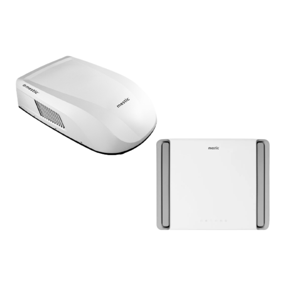
- Page 1 Rooftop air conditioner RTA-2600 8870 BTU/h (1160 W) Baby it’s COOL 53 dB INSIDE Mode 4 speeds 35 kg User instructions EN SMART ADVENTURE...
-
Page 3: Table Of Contents
A few words about your new air conditioning unit Electrical data Electric diagram Packing list Parts name Operation of wireless remote controller Control panel Installation instruction Step 1 - sticking the sealing strip and sponge pieces on the outdoor unit Step 2 - selecting an installation location &... - Page 5 WARNING: • This appliance is not intended for use by persons (including children) with reduced physical, sensory or mental capabilities, or lack of experience and knowledge, unless they have been given supervision or instruction concerning use of the appliance by a person responsible for their safety. Children should be supervised to ensure that they do not play with the appliance.
- Page 6 INSTALLATION PRECAUTION WARNING: • Observe all governing codes and ordinances. • Do not use damaged or non-standard power cord. • Be caution during installation and maintenance. Prohibit incorrect operation to prevent electric shock, casualty and other accidents. • Before turning on the unit, please open the horizontal louver of indoor unit by hand, Otherwise, the cool air can’t be blown out and there will be condensate water on the horizontal louver.
- Page 7 INSTALLATION PRECAUTION Requirements Forelectric Connection Safety precaution Must follow the electric safety regulations when installing the unit. According to the local safety regulations, use qualified power supply circuit. For appliances with type Y attachment,the instructions shall contain the substance of the following.If the supply cord is damaged,it must be replaced by the manufacturer, its service agent or similarly qualified persons in order to avoid a hazard.
-
Page 8: A Few Words About Your New Air Conditioning Unit
A FEW WORDS ABOUT YOUR NEW AIR CONDITIONING UNIT Thank you for choosing the Recreational Vehicle Air Conditioner. This manual will supply you with all the information for installation, operation and maintenance. Take a few minutes to discover how to get the most in cooling comfort and economic operation from your new air conditioner. -
Page 9: Electric Diagram
ELECTRIC DIAGRAM Ceiling Assembly CONNECTOR DISP1 DISPLAY BOARD ROOM ROOM SENSOR WIFI CONNECTOR WIFI LAMP MODULE MODULE OPTIONAL Roof Top Air Conditioner CAP. OUTDOOR TUBE OUTROOM 4-WAY TUBE SENSOR SENSOR SENSOR VALVE IN_FAN YEGN MOTOR (20K) (20K) (15K) (WH) (BK) 4WAY T-SEN DISP1... -
Page 10: Packing List
PACKING LIST Owner’s manual Foam (up) 16. Bundle Mounting plate Foam (accessory) 17. Bolt sub-assy M6X25 Remote controller 10. Sponge (foam accessory) 18. Tapping screw Battery (AAA 1.5V) 11. Mounting plate sub-assy Double-sided gummed paper 12. Bolt sub-assy M8X135 Remote controller holder 13. -
Page 11: Parts Name
PARTS NAME Indoor Unit Filter sub-assy Air-in grille LED indicator Air-outgrille Control panel (membrane) (Display content or position may be different from above graphics, please refer to actual products) Remote controller Outdoor Unit Outer case Air-in grille Drainage outlet Chassis Notice: Actual products may be different from above graphics, please refer to actual products. -
Page 12: Operation Of Wireless Remote Controller
OPERATION OF WIRELESS REMOTE CONTROLLER Buttons ON/OFF button Mode button Fan button - / + button Menu button LED button Turbo button SET button Icons on display screen Set fan speed Send signal Auto mode Cool mode Dry mode Fan mode Heat mode Sleep mode Light... - Page 13 INTRODUCTION FOR BUTTONS ON REMOTE CONTROLLER Note: • This is a universal remote controller, it can be used for multifunctional air conditioners. If an air conditioner model does not have a specific function, and the corresponding button is pressed, the unit will continue running in its original status.
- Page 14 4. - / + button • Press the “+” or “-“ button once to increase or decrease the set temperature by 1°C(°F). Hold the “+” or “-“ button down for at least 2 seconds, and the set temperature will change quickly. Once the “+” or “-“ button is released after setting the temperature, the temperature indicator on the air conditioner will change accordingly.
- Page 15 • Clock function With the clock function, the clock time can be set. When the clock function is active, the “ ” icon flashes on the remote controller. Press the “+” or “-“ button within 5 seconds to set the clock time. By pressing the button “+”...
- Page 16 COMBINATION BUTTONS Child lock function • Press the “+” and “-“ button simultaneously to turn on or to turn off the child lock function. When the child lock function is on, the “ ” icon is displayed on the remote controller. If the remote controller is now used, the “ ” icon will flash three times without sending a signal to the air conditioner.
-
Page 17: Control Panel
CONTROL PANEL Note: If the remote controller is missing, operate on the control panel. ON/OFF temp. COOL Reciever indicator indicator indicator window HEAT indicator ON/OFF button Operation starts when pressing this button, and stops when pressing this button again. LIGHT button Press this button to turn on or turn off display light on indoor unit. -
Page 18: Installation Instruction
INSTALLATION INSTRUCTION BEFORE INSTALLATION Testrun the unit with proper power supply. Refer to the operation instruction section in the Owner’s Manual Operation & Installation. Make sure all the controls operate correctly then disconnect the power supply of the unit. WARNING •... -
Page 19: Step 2 - Selecting An Installation Location
STEP 2-SELECTING AN INSTALLATION LOCATION & INSTALLING THE ROOF TOP AIR CONDITIONER Your air conditioner has been designed for use in recreational vehicles. Check the roof of the vehicle to determine if it can support both the roof top unit and the ceiling assembly without additional support. Make sure the interior ceiling mounting area will not interfere with existing structures. - Page 20 INSTALLATION METHOD OF THE MOUNTING PLATE If the roof of the vehicle already has an 400x400mm opening: • Choose the installation position for the air conditioner. The mounting adapter is suitable for an opening size of 400×400mm. Operation method: • Make sure the installation surface is flat.
- Page 21 Note: Try your best to put the unit on the horizontal surface for operation. The unit can only operate for a short time at the maximum sloping angle of 5º for preventing water leakage. Level Level Level Above Level 5º Max Above or below Level Below Level 0º...
-
Page 22: Step 3-Mounting Outdoor Unit
STEP 3-MOUNTING OUTDOOR UNIT Open the package and take out the outdoor unit 1) When taking out the outdoor unit after unpacking, do not lift the air outlet grille at the back of outer case (see Figure4-1). Figure 4.1 Installing the outdoor unit on the mounting adapter: •... -
Page 23: Step 4-Installing The Ceiling Assembly
STEP 4-INSTALLING THE CEILING ASSEMBLY NOTICE Make sure that you have properly matched the roof top air conditioner and interior ceiling assembly.Caution before tightening bolts: The applicable thickness of vehicle roof ranges from 30mm~80mm. Before tightening bolts, screw in the four bolts manually and prohibit screwing forcibly. When screwing bolts, you can use automatic tool. - Page 24 The following step by step instructions must be performed in the following sequence to ensure proper installation. Carefully take the ceiling assembly out of the carton Before installing the air duct assembly of the indoor unit of recreational vehicle air conditioner, Remove the ceiling grille from the ceiling assembly.
-
Page 25: Step 5 - Electrical Wiring
ELECTRICAL WIRING STEP 5-ELECTRICAL WIRING ROUTING 220-240V AC WIRING WARNING : Make sure that all power supply to the unit is disconnected before performing any work on the unit to avoid the possibility of shock or injury and/or damage to the equipment. After the interior ceiling assembly frame is properly secured to the roof top air conditioner, the following electrical connections must be performed. - Page 26 Fig 8.1 Fig 8.2 Fig 8.3 Fig 8.4 NOTE Cable ties must be attached to the area with both sponge and thermal insulating jacket; Before installing the front panel of indoor unit, put the thermal insulating jacket on top of the air duct. Insulating sheath Wind-path Front panel...
-
Page 27: Step 6 - Completing The Installation
COMPLETING THE INSTALLATION STEP 6-COMPLETING THE INSTALLATION To complete the installation and system checkout requirements, the following steps must be performed. Check the thermostat position. Make sure the thermostat is routed through the holding guide and is not touching any metal surface. Secure the ceiling grille to the ceiling assembly wind-path with 4 screws. -
Page 28: Troubleshooting Guide
TROUBLESHOOTING TROUBLESHOOTING GUIDE If you have problems with your recreational vehicle air conditioner, check this guide before contacting your service representative. TROUBLE POSSIBLE CAUSE SOLUTION The unit can not The unit may not be connected to the power Check the power supply of the vehicle start supply correctly. -
Page 29: Error Code
ERROR CODE When air conditioner status is abnormal, temperature indicator on indoor unit will blink to display corresponding error code. Please refer to below list foor indenrification of error code. Above indicator diagram is only Indoor for reference. Please refer to actual display product for the actual indicator and position. -
Page 30: Normal Maintenance Procedures
NORMAL MAINTENANCE PROCEDURES ACTIVETY FREQUENCY Remove the cover and wash the Twice a year. condenser coil Clean the filter When the air conditioner FILTER CHECK light (More frequent cleaning may be necessary is on. depending on the air quality) HOW TO REMOVE THE AIR FILTER Push both sides of the air intake grill on the positions marked with “PUSH”. - Page 31 DECLARATION OF CONFORMITY RTA-2600 Hereby Gimeg Nederland B.V. declares that the device , applies all basic requirements and other relevant regulations listed in the European directive for electromagnetic compatibility (2014/30/EU) and low voltage directive (2014/35/EU).
- Page 32 Importer: Gimeg Nederland B.V. Strijkviertel 27 3454 PH De Meern The Netherlands...
Need help?
Do you have a question about the RTA-2600 and is the answer not in the manual?
Questions and answers