Advertisement
Quick Links
INSTALLATION, OPERATION & APPLICATION GUIDE FOR DIGITAL WALL
WARNING!
This appliance is not intended for use by
young children or infirm persons unless they
have been adequately supervised by a
responsible person to ensure they can use the
appliance safely.
CAUTION!
This thermostat should be installed by trained
technicians only. Adhere to all local and
national codes and ordinances.
DISCONNECT ALL POWER TO THE SYSTEM
BEFORE INSTALLING, REMOVING, OR
CLEANING.
1980R189 (08-24-23)
THERMOSTAT 9420*381 & 9420*382
Features
The thermostat wiring is factory installed
by the OEM (Original Equipment
Manufacturer). RV Products suggests the
thermostat wiring be a minimum of 20
gauge. The thermostat is intended for use
with a 12 VDC control circuit that does not
exceed 2 amps.
The thermostat is equipped with a self-
resetting PTC fuse located in the
thermostat. The fuse is designed to "open"
if the circuit is mis-wired or if there is a
short in the system.
If the PTC fuse continues to "open", the
fault must be located and corrected.
The thermostat includes a mounting plate,
2 screws and 2 wall anchors.
An oversized accessory wall plate
(9420*3501) is available for purchase if
needed.
Thermostat and Room Temperature
Sensor Location
• An internal temperature sensor on the
thermostat can act as the room sensor.
• Alternatively, a remote temperature
sensor can be connected to the
thermostat to the SENS connectors. The
thermostat will show "REMOTE" at the
top of the display. This situation would
allow the thermostat to be located
virtually anywhere in the coach, as long
as the user can access the thermostat to
operate it.
The Remote Room Sensors available are
8330-5191 (white) and 8330-3101
(black).
Advertisement

Related Manuals for Airxcel Coleman-Mach 9420 381


Summary of Contents for Airxcel Coleman-Mach 9420 381
- Page 1 INSTALLATION, OPERATION & APPLICATION GUIDE FOR DIGITAL WALL THERMOSTAT 9420*381 & 9420*382 Features The thermostat wiring is factory installed by the OEM (Original Equipment Manufacturer). RV Products suggests the thermostat wiring be a minimum of 20 gauge. The thermostat is intended for use with a 12 VDC control circuit that does not exceed 2 amps.
-
Page 2: Installation
Installation 2. Affix the mounting plate to the wall using two screws. Wall anchors are ELECTRICAL SHOCK HAZARD – Turn off power included if needed to secure the at the main service panel by removing the mounting plate to the wall. fuse or switching the appropriate circuit breaker to the OFF position before removing 3. - Page 3 Wire Labeling and Connectors The labeling of the inputs/outputs of the Label on Definition thermostat can be found on the rear of the Thermostat thermostat. Voltage input (+12V) Refer to the table below for labels and definitions. Ground Compressor output Fan high output Fan low output Gas heat output...
- Page 4 Dip Switches HVAC Mode and Fan Mode Selection The dip switches will enable/disable certain Upon powering up the thermostat, the functions of the thermostat. To apply any display will show the HVAC mode set to ‘Off’, changes to the dip switches after initial the fan mode set to ‘Off’, the current installation, the device must be rebooted.
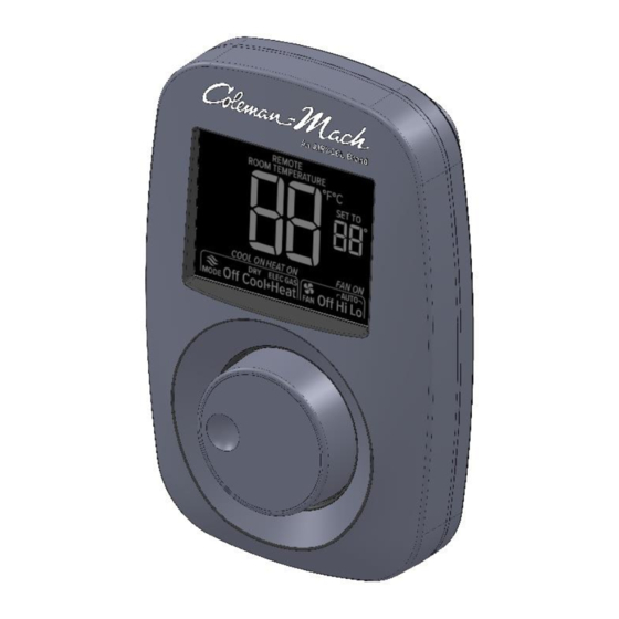
- Page 5 OPERATION GUIDE FOR DIGITAL WALL THERMOSTAT 9420*381 & 9420*382 Operation The thermostat screen has a black background with a white LCD display. A rotary knob (to switch between selections and temperature settings) with a push button feature to select desired setting. WARNING! This appliance is not intended for use by young children or infirm persons unless they have been adequately supervised by a responsible person to ensure they can use the appliance safely.
- Page 6 Thermostat Display Remote Sensor Installed – HVAC Mode – Remote displays when the thermostat is Displays the mode of HVAC operation controlled by a sensor remote to the user selected. thermostat. In this example, a remote Fan State – sensor is used therefore the thermostat Displays when the fan is operating.
- Page 7 Temperature Unit Change While in cool+heat mode, a 15 minute timer (auto change-over timer) will prevent the The thermostat can display temperature in opposite HVAC mode from operating if the either Fahrenheit or Celsius. To change the set temperature and room temperature temperature units, press and hold the knob remain within 2°...
- Page 8 “HI”. AIRXCEL, INC. – RV Products Division PO Box 4020 • Wichita, KS 67204 • 574.247.9235 • www.AIRXCEL.com Email Support: www.RVPSupport@airxcel.com • Email Sales: RVPSales@airxcel.com Coleman is a registered trademark of The Coleman Company, Inc. used under license. Mach is a registered trademark.
Need help?
Do you have a question about the Coleman-Mach 9420 381 and is the answer not in the manual?
Questions and answers
When I push the selector knob in an attempt to move the mode selection, nothing happens. It just continues to blink the temperature and does not allow any changes as to the mode. How do I change the mode on the unit?
If the selector knob does not respond when trying to change the mode on the Airxcel 9420 381 unit, try rebooting the device. Changes to settings, including dip switches that control functions like HVAC mode, require a reboot after adjustment. Refer to the manual reboot section for instructions. If the knob still does not work after rebooting, the unit may need servicing.
This answer is automatically generated