Munters Communicator 2.0 Installation And User Manual
For trio
Hide thumbs
Also See for Communicator 2.0:
- Manual for use and maintenance (52 pages) ,
- Manual for use and maintenance (54 pages)

Related Manuals for Munters Communicator 2.0


Summary of Contents for Munters Communicator 2.0
- Page 1 Communicator Installation and User Manual for Trio Communicator 2.0 for Trio Communication System Ag/MIS/UmEn-2774-07/20 Rev 1.9 P/N: 116801...
- Page 2 Munters reserves the right to effect modifications to the apparatus in accordance with technical and legal developments.
-
Page 3: Table Of Contents
Connecting the Communicator 2.0 to a Peripheral Device ........ 12 3.10 Connecting the T-Box to External Devices ............12 3.11 Setting Up a Communicator 2.0 / Trio LAN ............13 3.12 Enabling SMS Messages ..................15 3.13 Testing the Battery ....................15 ........................ - Page 4 Resetting the Siren ............... 27 5.3.2.1 Resetting the Alarm ..............27 5.3.2.2 Acknowledging a Message ............27 5.3.2.3 Testing the Communicator 2.0 ................28 Additional Functions .................... 28 5.5.1 Software Upgrade ................... 5.5.2 Battery Status ....................................5.5.3 Controllers Connectivity ..............
-
Page 5: Introduction
Munters equipment. 1.3 Notes Date of release: October 2018 Munters cannot guarantee to inform users about the changes or to distribute new manuals to them. All rights reserved. No part of this manual may be reproduced in any manner whatsoever without the expressed written permission of Munters. -
Page 6: Introduction To The Communicator
2 Introduction to the Communicator Communicator 2.0 provides complete access to your Munters Trio controllers, with alarms and events sent directly to your mobile device, PC, or tablet. From one computer, tablet, or smartphone, you can manage an entire network. -
Page 7: Hardware Installation
3.1 Precautions Observe the following precautions when using your unit. Keep the Communicator 2.0 as far as possible from heavy contactor boxes and • other sources of electrical interference. Do not connect communication wire shields, which go from one house to another •... -
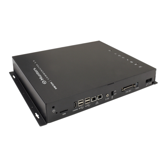
Page 8: Interior
(refer to Enabling SMS Messages, page 15) HDMI port (computer screen) Audio out (external speaker) (refer to Connecting the Communicator 2.0 to a Peripheral Device, page 12) USB ports (mouse, KBD) (refer Internet line port(refer to to Connecting the Connecting the Communicator 2.0 Communicator 2.0 to a... -
Page 9: Mounting The Communicator 2.0
Line Modem Card This card is under the LED board Not used Board Cell Modem SSD Card Main CPU 3.4 Mounting the Communicator 2.0 Figure 3: Dimensions (mm) Mount the unit using the four supplied screws. • © Munters AB, 2020 Trio... -
Page 10: Grounding
Figure 4: Mounting 3.5 Grounding Connect the ground cable to the dedicated ground terminal. • Figure 5: Grounding Schematic CAUTION The Communicator 2.0 must be grounded at all times! © Munters AB, 2020 Trio... -
Page 11: Connecting The Communicator 2.0 To The Internet
NOTE The telephone line-modem output connection wiring must provide double insulation. Use minimum 26 AWG wiring or larger for telephone line connection. 3.8 Attaching the Antenna If the Communicator 2.0 comes with a cell modem, attach the antenna. Figure 8: Antenna Attachment © Munters AB, 2020 Trio... -
Page 12: Connecting The Communicator 2.0 To A Peripheral Device
3.9 Connecting the Communicator 2.0 to a Peripheral Device If required, connect a screen and key board to the Communicator 2.0 (via the four • USB or single HDMI ports). NOTE: You’ll need to connect the Communicator 2.0 to these devices for the Activation. -
Page 13: Setting Up A Communicator 2.0 / Trio Lan
3.11 Setting Up a Communicator 2.0 / Trio LAN Connect the Communicator 2.0 and Trio units via a local intranet. NOTE The Communicator 2.0 and Trio units can be plugged into any port. The above drawing is an example only. - Page 14 Figure 12: Trio Ethernet port CAUTION Connect the intranet cable to port 2. Do not connect the cable to port 1. Internal port (do not use this port) Ethernet port RJ-45 cable © Munters AB, 2020 Trio...
-
Page 15: Enabling Sms Messages
3.12 Enabling SMS Messages Sending SMS message requires a Communicator 2.0 having an internal modem • (supplied by Munters if ordered). This modem will support your cellular infrastructure and region (4G US, 4G ROW, 3G) Insert a 3G or 4G standard SIM card as indicated: •... -
Page 16: Specifications
Metal Box Dimensions (L x W x H) 416 x 266 x 60 mm Ambient Climate ° ° ° ° Operating Temperature Range to +35 ° ° ° ° Storage Temperature Range to +50 Certification © Munters AB, 2020 Trio... -
Page 17: Functionality
Additional Functions • 5.1 Farm Settings Use this screen to define functions related to Communicator 2.0’s connection to your farm. Farm Name: This name appears on your screen. • Number of Trios to be Scanned: Click the -/+ buttons to enter the number of •... -
Page 18: Alarms
This section describes how to configure the alarms. All other functions are described in the Platinum Touch manual. Alarms can only be configured locally. Anyone viewing the Communicator 2.0 • screen via the web will not see Alarm System in the Settings icon. -
Page 19: Editing The Settings
5.2.1 E DITING THE ETTINGS 1. Click the Alarm Settings tab. The screen displays the current alarm settings along with Communicator 2.0 parameter settings. 2. To edit the Alarm Settings click © Munters AB, 2020 Trio... - Page 20 Country of installation: Choose from the drop down list. o Generator Ip Address (US customers only): Users having a backup generator connected to the Communicator 2.0 can enter the generator’s IP address. Communicator 2.0 will transmit any alarms from the generator.
-
Page 21: Adding Contacts
You can enter any email address but only the activation address enables push notifications. Message Type: Mark the checkbox(es) next to message type(s) that this contact is • to receive. o Email o Push notifications © Munters AB, 2020 Trio... - Page 22 The first level of security is the contact list; only these numbers can interact with the Communicator 2.0. If a pin code is added, only someone having the code can reset the alarms, even when calling from an authorized phone number.
-
Page 23: Alarm And Events History
VENTS ISTORY Click Alarms History to view a view a list of alarms and information about each • alarm. Click Events History to view a list of events connected to the Communicator 2.0. • 5.2.4 D IGITAL NPUTS Communicator 2.0 supports an eight dry contact digital input card (found in the External Box) that can be programmed as normally open / normally closed input. - Page 24 NO means normally open. If there is a change from the usual state (device closes), an alarm occurs. o Allow to Reset: When this function is not checked, Communicator 2.0 sends a message to every contact (in the order given in the priority list) when an alarm is generated.
-
Page 25: Disable Alarms
ESPONDING TO AN UDIO ESSAGE Communicator 2.0 sends voice messages to the designated people on the contact list. This section details the procedure to follow when an audio alarm is received. NOTE: This service is provided by the Communicator 2.0 ONLY if the contact is properly defined with contacts and the "VOICE"... -
Page 26: Receiving The Message
"Disable <confirmed / failed>!" message is repeated and returns to House Alarm • Messages NOTE: If at any time an incorrect key is pressed or if nothing is pressed, the system repeats itself three times and then ends the call. © Munters AB, 2020 Trio... -
Page 27: Responding To A Text Message
5.3.2 R ESPONDING TO A ESSAGE This section details how to respond to a text message sent from Communicator 2.0 to a mobile phone. The response can reset a siren, an alarm, or acknowledge the messages. Resetting the Siren •... -
Page 28: Testing The Communicator 2.0
UPD file. a. Place the file on a disk on key/flash drive. b. Place the disk on key/flash drive into the Communicator 2.0's USB port. 2. On the main screen, click the settings icon . From the drop down list select Software Update. -
Page 29: Battery Status
If you did not place the disk on key in the USB port or if the disk does not contain a program, an error message appears. 5.5.2 B ATTERY TATUS Click on the battery symbol to view the Communicator 2.0's battery status. • NOTE: An alarm is sent when the Battery switch is turned off. © Munters AB, 2020 Trio... -
Page 30: Controllers Connectivity
Click on the house symbol to view the status of the controller connectivity. Click on a specific house or room to go to that Trio unit. • If a house has alarms, the house is red. • © Munters AB, 2020 Trio... -
Page 31: About Tab / Technical Support
In the Settings icon, click About to display the product and software version. Send this information to technical support in the event that you require assistance. The Support ID enables remote technical support from Munters or from your dealer. © Munters AB, 2020 Trio... -
Page 32: Diagnostics
Off: No active alarm(s) • On: Active alarm Battery • Red: Battery is disconnected • Red Blinking: Battery is not charging (consult with dealer immediately) • Green Blinking LED: Battery is charging • Green: Battery is charged © Munters AB, 2020 Trio... -
Page 33: Appendix A: Changing The Battery
7 Appendix A: Changing the Battery Munters recommends installing a new battery every two years. Change the battery between flocks or herds. • Order a new battery from your dealer. • To replace the battery: 1. Disconnect the AC power. - Page 34 11. Place the cover in place and insert the screws. 12. Place the unit on the wall (optional) and reconnect the cables. 13. Turn on the battery switch, apply AC power, and verify that the Power LED is lit. © Munters AB, 2020 Trio...
-
Page 35: Appendix B: It Setup
Employ a standard home router, using the default settings, and all devices on the same router. o On the local network, Communicator 2.0 and Trio must have same the subnet mask (subnet mask must be 255.255.255.0. o Three first sections of the Communicator 2.0 and Trio IP address must have the same numbers (i.e 192.168.1.x). -
Page 36: Lan Cable Information
The switch is wired to the router and modem to access the Internet. • Switches can be wired to each other by Ethernet cables, each one splitting off to • other devices. Gigabit switches support 100 and 1,000 Mbps. • © Munters AB, 2020 Trio... -
Page 37: Typical Setups
8.3 Typical Setups Figure 14: Typical Poultry Installation 1 © Munters AB, 2020 Trio... - Page 38 Figure 15: Typical Poultry Installation 2 © Munters AB, 2020 Trio...
- Page 39 Figure 16: Typical Swine Installation © Munters AB, 2020 Trio...
-
Page 40: Warranty
Munters plant was required: if this is not done, the user is fully responsible for the damage which they could suffer. - Page 41 The liability of the manufacturer Munters ceases in the event of: • dismantling the safety devices; • use of unauthorised materials; • inadequate maintenance; • use of non-original spare parts and accessories. Barring specific contractual terms, the following are directly at the user’s expense: •...
Need help?
Do you have a question about the Communicator 2.0 and is the answer not in the manual?
Questions and answers