Sign In
Upload
Download
Add to my manuals
Delete from my manuals
Share
URL of this page:
HTML Link:
Bookmark this page
Add
Manual will be automatically added to "My Manuals"
Print this page
×
Bookmark added
×
Added to my manuals
Manuals
Brands
Panasonic Manuals
Telephone
KX-TCD455GM
Service manual
Panasonic KX-TCD455GM Service Manual
Digital cordless phone metalic gray version (for germany)
Hide thumbs
1
2
3
4
5
6
7
8
9
10
11
12
13
14
15
16
17
18
19
20
21
22
23
24
25
26
27
28
29
30
31
32
33
34
35
36
37
38
39
40
41
42
43
44
45
46
47
48
49
50
51
52
53
54
55
56
57
58
59
60
61
62
63
64
65
66
67
68
69
70
71
72
73
74
75
76
77
78
79
80
81
82
83
84
85
86
87
88
89
90
91
92
93
94
95
96
97
98
99
100
101
102
103
104
105
106
107
108
109
110
111
112
113
114
115
116
117
118
119
120
121
122
123
124
125
126
127
128
129
130
131
132
133
page
of
133
Go
/
133
Bookmarks
Advertisement
Quick Links
Download this manual
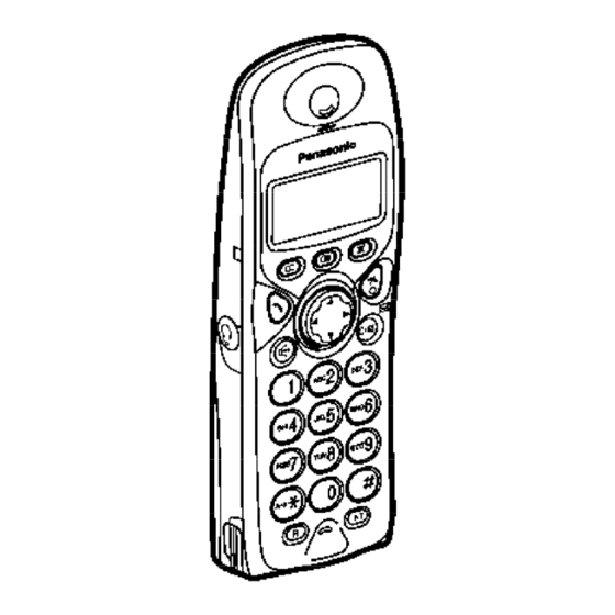
ORDER NO. KM40306110C2
Telephone Equipment
KX-TCD455GM / KX-A145EXM
Digital Cordless Phone
Metalic Gray Version
(for Germany)
SPECIFICATIONS
1
Previous
Page
Next
Page
1
2
3
4
5
Advertisement
Need help?
Do you have a question about the KX-TCD455GM and is the answer not in the manual?
Ask a question
Questions and answers
Related Manuals for Panasonic KX-TCD455GM
Telephone Panasonic KX-TCD715EM Service Manual
(106 pages)
Telephone Panasonic KX-TCD961RUB Service Manual
Digital cordless phone (4 pages)
Telephone Panasonic KX-TCD505HKM Service Manual
Telephone equipment digital cordless phone (147 pages)
Telephone Panasonic KX-TCD410RUM Service Manual
(90 pages)
Telephone Panasonic KX-TCA151AXM Service Manual
Digital cordless phone (121 pages)
Telephone Panasonic KX-TCD510RUM Service Manual
(105 pages)
Telephone Panasonic KX-TCD540NZM Service Manual
(198 pages)
Telephone Panasonic KX-TCD725AXM Service Manual
Telephone equipment (85 pages)
Telephone Panasonic KX-TC1460W Getting Started
(6 pages)
Telephone Panasonic KX-TC1503B Service Manual
(86 pages)
Telephone Panasonic KX-TC1701B User Manual
900 mhz cordless phone (52 pages)
Telephone Panasonic KX-TC1481B User Manual
900mhz cordless phone (41 pages)
Telephone Panasonic KX-TC1713B User Manual
900mhz cordless phones (69 pages)
Telephone Panasonic KX-TCA256 Quick Manual
Dect portable station (12 pages)
Telephone Panasonic KX-TC1466AGB Service Manual
(14 pages)
Telephone Panasonic KX-TG1283BXS Service Manual
Digital cordless answering system (99 pages)
This manual is also suitable for:
Kx-a145exm
Print
Rename the bookmark
Delete bookmark?
Delete from my manuals?
Login
Sign In
OR
Sign in with Facebook
Sign in with Google
Upload manual
Upload from disk
Upload from URL


Need help?
Do you have a question about the KX-TCD455GM and is the answer not in the manual?
Questions and answers