Table of Contents
Advertisement
Quick Links
Instructions, M-611, Software Rev. R.
Rev. 12/19/2023
INSTRUCTIONS
INSTALLATION, OPERATION, AND
MAINTENANCE
KAHLENBERG MODEL M-611
SOUND AND LIGHT (WHISTLE) CONTROL
M-611 SOUND AND LIGHT CONTROL, BULKHEAD OR FLUSH MOUNT, IP56 ENCLOSURE, WITH
BACKLIT DIMMABLE MEMBRANE SWITCH, 110-240 VOLT A.C. 50/60HZ 1 PH., AND 24 VOLT D.C..
CONTROLS HORNS, BELL AND GONG, AND MORSE LIGHT WHEN MANEUVERING AND IN RESTRICTED
VISIBILITY PER COLREG '72 INCLUDING SOLAS GENERAL EMERGENCY ALARM. BASIC DIMENSIONS:
7.5'' x 5'' x 3.375'' (191mm x 127mm x 86mm). Net Weight: 2.62 lbs./ 1.19 kg, RAL 9005 JET BLACK,
PER DRG. 3-6540. (**INCLUDES SPARE FUSE SET INTERNAL TO UNIT)
1
Advertisement
Table of Contents

Related Manuals for Kahlenberg M-611


Summary of Contents for Kahlenberg M-611
- Page 1 KAHLENBERG MODEL M-611 SOUND AND LIGHT (WHISTLE) CONTROL M-611 SOUND AND LIGHT CONTROL, BULKHEAD OR FLUSH MOUNT, IP56 ENCLOSURE, WITH BACKLIT DIMMABLE MEMBRANE SWITCH, 110-240 VOLT A.C. 50/60HZ 1 PH., AND 24 VOLT D.C.. CONTROLS HORNS, BELL AND GONG, AND MORSE LIGHT WHEN MANEUVERING AND IN RESTRICTED VISIBILITY PER COLREG '72 INCLUDING SOLAS GENERAL EMERGENCY ALARM.
-
Page 2: Table Of Contents
Instructions, M-611, Software Rev. R. Rev. 12/19/2023 Table of Contents Page WARNING! This instruction manual contains important Introduction instructions for operating this product. Read this manual thoroughly before Important Safety Instructions operating the product. General Description Failure to properly follow all the... -
Page 3: Important Safety Instructions
ALWAYS remove and lock out/tag out electrical power before performing maintenance. GENERAL DESCRIPTION The function of the M-611 Sound and Light Control is to provide convenient operation of sound signaling devices including navigation horns (ship’s whistles), Bell, Gong, and Morse Light from a single control panel. -
Page 4: Package Contents
Rev. 12/19/2023 PACKAGE CONTENTS The M-611 Sound and Light Control ships as a complete assembled unit. In addition, (3) three of each P546-12 and P546-10 Button Overlays are included in a poly bag taped to the outside of the M-611 enclosure. The complete M-611 and button overlays are packaged together within anti-static wrap. - Page 5 Rev. 12/19/2023 Setting SW1 Switches On the internal circuit board of the M-611 there is a switch assembly labeled SW1. Settings on this switch assembly determine permanent functionality of the unit not programmable from the keypad. Settings and functionality are as follows:...
- Page 6 Proceed to step 2. For 2 or more M-611 Controls, Tab 3 must be set to ON. Tab 1 and 2 must be set to OFF on the main M-611 Unit that is wired to the sound and light producing devices. Any additional M-611...
- Page 7 4mm x 40mm flat head screws (provided). An opening of 6-1/2” (165mm) wide x 4” (101mm) high should be made in the console where the unit is to be placed. The M-611 includes a gasket used to provide a seal between the bezel of the M-611 and the console surface. See details per Drg.
-
Page 8: Operation
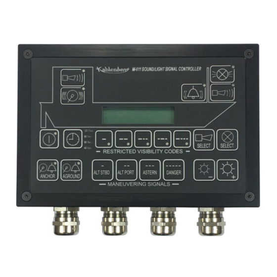
Rev. 12/19/2023 Connecting Multiple M-611 Units via CAN Connection: If installing more than one M-611 unit on a vessel, the CAN connection must be utilized so the M-611 units can communicate with each other. When installed with the CAN connection (Terminals 37-39 per Drg. - Page 9 The buttons above the ship graphic on the membrane switch panel correspond to each of the devices controlled by the M-611 unit. To operate any device connected to the M-611 on an “At-Will” basis, simply press the appropriate button as follows:...
- Page 10 “Automatic On-Off” switch. Any other At-Will button, externally connected or internal to the M-611 will discontinue the automated signal which must be restarted at the “Automatic On- Off” switch, or at a remotely located “Automatic On-Off” switch if installed. The General Alarm, Abandon Ship, Anchor, Aground or Maneuvering Signals if activated will also discontinue the restricted visibility code.
- Page 11 General Emergency Alarm: (See also SW1 Switch Settings in “Installation” Section) The M-611 is able to generate the General Emergency Alarm (Seven Short Signals followed by one long signal repeating without pause (19 seconds total code cycle) per SOLAS requirements.
- Page 12 Abandon Ship Code: The M-611 is able to generate the Abandon Ship Code (1 second on, 1 off, 7 on, 1 off, 1 on, 1 off, 7 on, 3 seconds off, repeating) per certain flag state requirements. This must be started and stopped by an external push button (momentary or maintained, not included with M-611) that is constructed in accordance with requirements as stated by various flag state authorities.
- Page 13 M-611 unit. This momentary push button when pressed will also discontinue any automatic signaling cycle currently running on the M-611 Unit. The horn will sound continuously as long as the button is pressed. When released, the horn or horns will stop sounding.
-
Page 14: Troubleshooting
CARE AND MAINTENANCE Troubleshooting, Repair, and Service: The M-611 Sound and Light Control is a solid state device designed to provide many years of maintenance free operation. However, in the event that a power surge takes place or inappropriate wiring connections are made, fuses within the unit will fail, preventing damage to the circuitry. -
Page 15: Reference Document List
Rev. 12/19/2023 REFERENCE DOCUMENTS: Outline Dimensions, M-611 Whistle Control Drawing 3-6540 Parts List, M-611 Whistle Control Drawing 3-6542 General Wiring Diagram, M-611 Whistle Control Drawing 3-6705 Kahlenberg Industries, Inc. 1700 12 St., P.O. Box 358 Two Rivers, WI 54241 USA...
Need help?
Do you have a question about the M-611 and is the answer not in the manual?
Questions and answers