Table of Contents
Advertisement
Quick Links
M-485B Horn Signal Controller Instructions
Rev. 4/12/2022
INSTRUCTIONS
INSTALLATION, OPERATION, AND MAINTENANCE
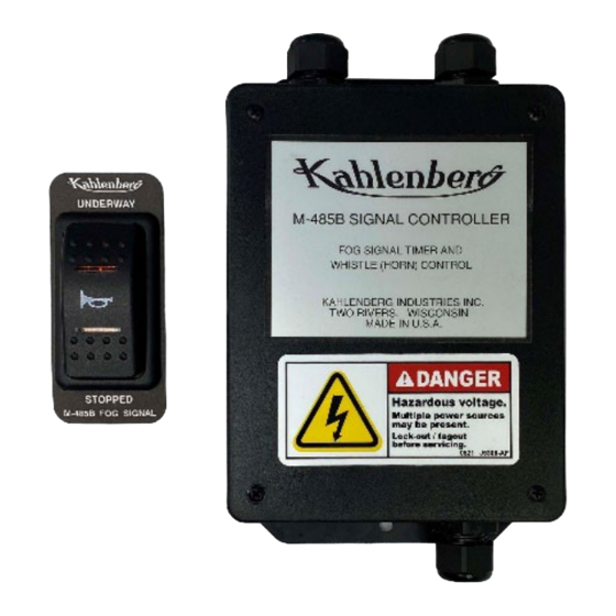
KAHLENBERG MODEL M-485B
HORN SIGNAL CONTROLLER
P.N. TI/37575/DC/ABC
M-485B SIGNAL CONTROLLER, FOG SIGNAL TIMER AND WHISTLE CONTROL, 12 OR 24 VOLT D.C.,
WITH ILLUMINATED M-129 TWO POSITION PANEL ROCKER SWITCH. INCLUDES FOG SIGNAL CODES
(RULE 35) FOR "UNDERWAY" AND "STOPPED", MOTOR AND SAILING VESSELS, PER IMO "COLREG
72" AND COMDTINST M16672.2D, PER DRG. 3-7575
PLEASE READ INSTRUCTIONS IN THEIR ENTIRETY
BEFORE PROCEEDING. INCORRECT INSTALLATION
WILL PERMANENTLY DAMAGE THIS UNIT!
www.kahlenberg.com
Customer Support: 1-920-793-4507
Advertisement
Table of Contents

Related Manuals for Kahlenberg M-485B


Summary of Contents for Kahlenberg M-485B
- Page 1 HORN SIGNAL CONTROLLER P.N. TI/37575/DC/ABC M-485B SIGNAL CONTROLLER, FOG SIGNAL TIMER AND WHISTLE CONTROL, 12 OR 24 VOLT D.C., WITH ILLUMINATED M-129 TWO POSITION PANEL ROCKER SWITCH. INCLUDES FOG SIGNAL CODES (RULE 35) FOR "UNDERWAY" AND "STOPPED", MOTOR AND SAILING VESSELS, PER IMO "COLREG 72"...
-
Page 2: Table Of Contents
M-485B Horn Signal Controller Instructions Rev. 4/12/2022 Table of Contents Page Introduction WARNING! This instruction manual contains important instructions for Important Safety Instructions operating this product. Read this manual thoroughly before operating the product. General Description Failure to properly follow all the... -
Page 3: Important Safety Instructions
M-485B. (12 or 24 Volt D.C.) The solenoid valve opens the air line to an air horn. The M-485B can also be changed internally to activate a 12 or 24 volt D.C. Electric Horn. -
Page 4: Package Contents
Model M-129 Rocker Switch. Enclosed in a separate poly bag taped to the M-485B are the M-129 Rocker Switch, P548-04 Mounting Bezel, and P356-11 Nameplate. There are no other loose items in the shipment other than included instructions. -
Page 5: Installation
Internal to the M-485A there is a jumper located at position J2 on the circuit board as shown below. The jumper is in this position as shipped from the factory. The restricted visibility codes in the M-485B are set for “MOTOR” vessels. www.kahlenberg.com... - Page 6 M-485B Horn Signal Controller Instructions Rev. 4/12/2022 To change the M-485B output to the restricted visibility codes for “SAIL” vessels, gently pull the jumper up off the pins and move it, to disconnect the jumper circuit as shown below. **NOTE: When moving the jumper to make changes the unit must also be re-powered for this change to take effect www.kahlenberg.com...
- Page 7 4.) Apply marine silicone sealant to the panel surface to seal the bezel. 5.) Mount the P548-04 Bezel in the hole and wipe off excess sealant. 6.) Bring the wire harness from the M-485B through the hole and make connections to the M-129 Switch per wiring diagram enclosed.
-
Page 8: Operation
I f the M -485B w ill be connected to an air horn solenoid valve of the sam e voltage All internal connections have been made in the M-485B at the factory to use the incoming M- 485B main power for the internal relay which supplies current to the horn. Make connections according to wiring diagram 3-7584, or wiring diagram 3-7577 if the Kahlenberg M-130 double pole “at will”... -
Page 9: Maintenance
M-485B. MAINTENANCE The M-485B is a solid state unit and is not user serviceable. Contact Kahlenberg Industries for any replacement parts that may be needed. Please have model number and serial number of the unit available when contacting us for assistance. - Page 10 M-485B Horn Signal Controller Instructions Rev. 4/12/2022 PROBLEM POSSIBLE CAUSE POSSIBLE SOLUTIONS M-485B is not functioning Blown Fuse See 2 Amp fuse on main circuit board. If fuse is blown, Incorrect wiring unit is drawing too much amperage. See “Electrical Connections”...
Need help?
Do you have a question about the M-485B and is the answer not in the manual?
Questions and answers