Table of Contents
Advertisement
Quick Links
Advertisement
Table of Contents

Related Manuals for Comelit VEDO5TPRW


Summary of Contents for Comelit VEDO5TPRW
- Page 1 USER MANUAL VEDO5TPR / VEDO5TPRW user manual...
-
Page 3: Table Of Contents
Table of contents Introduction.............................4 RFID sensing area.........................4 Screen: Code entry........................4 Indications............................5 Buzzer............................5 Key to indicator LEDs........................5 Main screen.............................6 System status..........................6 Alarm or tampering alert screen....................7 Quick commands from the home scen..................7 Arming.............................7 Disarming............................7 Arming with zones open........................8 Arming with zones excluded......................8 Arming with zones isolated......................9 Arming while faults are present....................9 Arming while tampering is present....................9... -
Page 4: Introduction
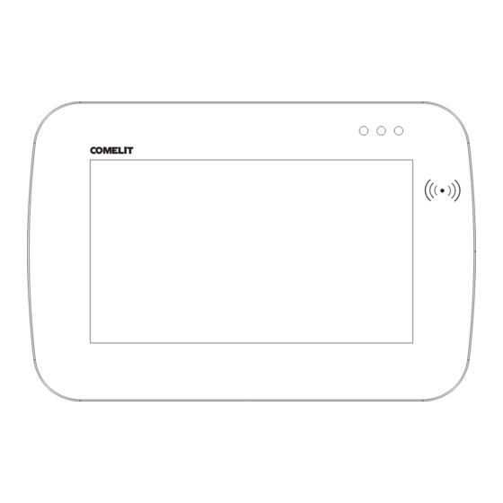
Introduction VEDO5TPR / VEDO5TPRW is a keypad with 5” touchscreen that is compatible with all sizes of Vedo control panels. Thanks to its many functions, it can be used to arm and disarm the system, check the status of the system and its areas and zones, and to view the users associated with the control panel and its telephone contacts list. -
Page 5: Indications
“•” symbols represents the time frequency of the beeps. The size of the symbols represents the relative volume of the beeps “•·” Key to indicator LEDs VEDO5TPR / VEDO5TPRW has a series of three LEDs in different colours on the front panel, which function as follows: Colour... -
Page 6: Main Screen
Main screen To access the main screen, simply touch the screen if it is off, or use the relevant icons if you are already accessing the menus. The main screen appears as shown in the figure, where the areas present in the control panel are indicated. -
Page 7: Alarm Or Tampering Alert Screen
Alarm or tampering alert screen In the event of alarms or sabotage, when the system is armed, a screen with a red background will appear indicating the event. In this example, with the system armed, a “Burglary” type alarm is occurring. The information will then remain available for reference within the “Event log”... -
Page 8: Arming With Zones Open
Arming with zones open If a zone is open during arming, and is not delayed and not available for exclusion, after the system analysis screen, the following screen will appear: If you press “Forcing” the system will be armed but the presence of an inhibited zone will be indicated by the LED flashing (inhibited status will remain until the next system disarming). -
Page 9: Arming With Zones Isolated
Arming with zones isolated If a zone is isolated during arming, after the system analysis screen has been shown the following screen will appear. It can be used to activate the zone, cancel the procedure, or continue to maintain isolation status (forcing), as shown below: Arming while faults are present If a fault is present during arming, after the system analysis screen has been shown the following screen will... -
Page 10: System Options
• Telephone contacts list • Area status • Output commands • Quick commands • App launch • Alarm options • Emulated keypad icon allowing access to the VEDO5TPR / VEDO5TPRW user manual through the scanning of a QR code is also present. -
Page 11: Zone Status
Zone status This option is used to view and change zone status. Each zone is identified by a different colour according to its status. Press “ALL” to filter by status type. IMPORTANT: zones in alarm and tamper condition are included in the open zones. Users This menu consists of a list of users present on the control panel (or previously registered using the Safe Manager software). -
Page 12: Event Log
Event log This option can be used to view the events stored in the Log. There are two event groups in the Event Log: • Event log: to view all events • Alarm log: to view alarm events only Both have direction arrows for scrolling. The date and time of the event stored in the memory will appear next to the arrows. -
Page 13: Output Commds
To arm or disarm (or partialise) an area, you will need to press the corresponding key. 1. Total area arming button 2. Partial area arming button (only available if the area belongs to a zone with Partial1/Partial2 attribute) 3. Area disarming button After pressing the arming/disarming buttons, if the action was executed, the “Action executed”... -
Page 14: Quick Commds
IMPORTANT: “Deactivate” and “Toggle” commands will only take effect if the output has been configured as bi-stable by the installer. Quick commands This option is used to carry out a quick command (or alarm) from those listed and to select which of them to show on the “main screen”, up to a maximum of 3 elements (by default “Stop alarm”, “Reset alarm”, “Enable installer”). -
Page 15: App Launch
This menu can be used to add new accounts (meaning Comelit App user accounts) by generating OTP (One Time Password) codes which remain valid for 10 minutes and should also be shown in the Comelit App when a new intruder protection device is added. In the image below, when you click on any account, a new activation code generation request is sent;... -
Page 16: Alarm Options
In the event of unforeseen code generation problems, the following screen will appear: Alarm options Press the Alarm Options button to access another menu containing the following options: • Enable installer • Register key • Delete key • Timer • Auto activation •... -
Page 17: Delete Key
1. Next, pass the key near the sensing area on the right-hand side of the device; the following screen will then appear: 2. Select the user to be associated with the key; the key description entry screen will then appear. The screen is the same as the one used for the phone book, to edit the telephone number description. -
Page 18: Timer
3. Select the key you wish to delete from the list. 4. After selecting the key you will be asked to confirm deletion. Timer This option can be used to select which timers are enabled for timed activation. The individual options can be disabled by pressing the ... -
Page 19: Configuration
• Information • Manufacturing Test Device ID Menu for assigning a unique ID to each VEDO5TPR / VEDO5TPRW device present (proceed using the progressive number order on the basis of the devices present). Device Password This option can be used to change the device password for the product (single digit with a value between 0 and 9: default value = 0) to protect it in the event of association with other VEDO devices. -
Page 20: Bus485 Speed
Bus RS-485 speed This option can be used to change the VEDO5TPR / VEDO5TPRW RS-485 BUS speed. Backlight Level This menu can be used to set the backlighting level for the device, as shown in the figure below. Lock screen... -
Page 21: Reset Configuration
Reset Configuration This option can be used to reset the product configuration to its factory conditions. Information This option can be used to view information relating to the product software version. VER.FW: 1.0.0 VER.EE: apv_v1_0_0_devel1 Manufacturing Test Menu reserved for the manufacturer Emulated keypad This option allows virtual reproduction of the VEDOKP or VEDOKPR keypad, with the full support of all the functions available on that keypad. - Page 24 C E R T I F I E D M A N A G E M E N T S Y S T E M S w w w . c o m e l i t g r o u p . c o m 1st edition 12/2023 Via Don Arrigoni, 5 - 24020 Rovetta (BG) - Italy code 2G40003194...
Need help?
Do you have a question about the VEDO5TPRW and is the answer not in the manual?
Questions and answers