Table of Contents
Advertisement
Quick Links
SERVICING ...................................................................................................................................... 2
CAUTION, MICROWAVE RADIATION ............................................................................................. 3
WARNING ......................................................................................................................................... 3
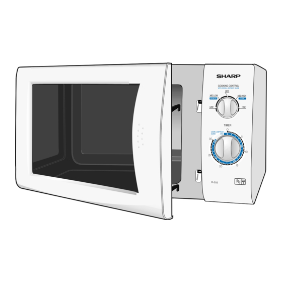
PRODUCT DESCRIPTION ............................................................................................................... 3
OPERATION DATA .......................................................................................................................... 4
DOOR SWITCHES ........................................................................................................................... 4
OUTPUT POWER TEST PROCEDURE ........................................................................................... 5
COMPONENT REPLACEMENT ....................................................................................................... 5
MICROWAVE LEAKAGE................................................................................................................... 7
WIRING / RE-WIRING........................................................................................................................ 8
SCHEMATIC DIAGRAM ................................................................................................................... 9
WIRING DIAGRAM ........................................................................................................................... 10
PARTS LIST ...................................................................................................................................... 11
EXPLODED ILLUSTRATION ............................................................................................................ 13
SERVICE MANUAL
R
COOKING CONTROL
WITH COOK & DEFROST GUIDE
MED
MED LOW
MED HIGH
DEFROST
COOK
LOW
HIGH
TIMER
O
COOK & DEFROST
GUIDE
(KG)
O
5
3O
1O
25
15
2O
R-202
R-202M
TABLE OF CONTENTS
SHARP CORPORATION
202M - 1
MICROWAVE OVEN
MODEL
R-202(W/G/BL)M
In the interests of user-safety the oven should be restored
to its original condition and only parts identical to those
specified should be used.
S04928R202M//
Page
Advertisement
Table of Contents

Related Manuals for Sharp R-202WM


Summary of Contents for Sharp R-202WM
-
Page 1: Table Of Contents
DOOR SWITCHES ........................... 4 OUTPUT POWER TEST PROCEDURE ................... 5 COMPONENT REPLACEMENT ....................... 5 MICROWAVE LEAKAGE........................7 WIRING / RE-WIRING........................8 SCHEMATIC DIAGRAM ........................9 WIRING DIAGRAM ........................... 10 PARTS LIST ............................11 EXPLODED ILLUSTRATION ......................13 SHARP CORPORATION 202M - 1... -
Page 2: Servicing
Sharp recommend that wherever possible, fault-finding is carried out with the supply disconnected. In some cases, it may be necessary to connect the supply with the cover removed to carry out fault investigation in the control circuitry. -
Page 3: Caution Microwave Radiation
CAUTION / WARNING WARNING CAUTION Servicing and repair work must be carried out only by MICROWAVE RADIATION trained service engineers. Do not become exposed to radiation from the The parts marked '*' on the parts list and schematic magnetron or other parts conducting microwave en- diagram have voltages in excess of 250V. -
Page 4: Operation Data
OPERATING SEQUENCE OFF CONDITION HIGH, MEDIUM HIGH, MEDIUM, MEDIUM Closing the door activates all door interlock switches (moni- LOW, LOW COOKING tored latch switch and latch switch). When the microwave oven is preset for variable cooking power, the line voltage is supplied to the power transformer IMPORTANT intermittently within a 26-second time base through the When the timer knob is at "0"... -
Page 5: Output Power Test Procedure
The power output of this oven is rated using the method specified by IEC-705. Full details of how to carry out this procedure can be found in the Sharp Technical Training notes which is available from Sharp Parts Centre (part number SERV-LITMW01). - Page 6 COMPONENT REPLACEMENT REMOVAL After any service, make sure of the following : 1. Disconnect the power supply cord. 1. Door latch heads smoothly catch latch hook through 2. Open the door slightly. latch holes and that latch head goes through center of 3.
-
Page 7: Microwave Leakage
MICROWAVE MEASUREMENT After any repair, the microwave oven must be checked for microwave leakage to ensure continued safe operation. BS EN 60335-2-25 specifies that the maximum permitted leakage with a load of 275 ml is 50 W/m (equivalent to 5 mW/cm a distance of 5 cm from the oven. -
Page 8: Wiring / Re-Wiring
(Magnetron, high voltage transformer,high voltage capacitor and high voltage rectifier assembly) b) Parts that become hot. (Heating elements, oven lamp,oven cavity magnetron and high voltage transformer) c) Sharp edges. (Bottom plates, oven cavity, waveguide flange, chassis support and other metallic parts) d) Movable parts. -
Page 9: Schematic Diagram
SCHEMATIC DIAGRAM CIRCUIT SUBJECT TO CHANGE WITHOUT NOTICE. DOOR CLOSED COOK OFF R-202M 230-240V 50Hz MICROWAVE CONDITION G-Y/18 EARTH 680k /0.5W 0.22 F /250V R-202M NOISE SUPPRESSION COIL NOISE FILTER UNIT 10M /0.5W 0.0033 F /250V 0.0033 F /250V OVEN THERMAL CUT-OUT SCHEMATIC... -
Page 10: Wiring Diagram
POWER SUPPLY CORD LIVE SW3: MONITORED TIMER TC: THERMAL CUT-OUT LATCH SWITCH UNIT (OVEN) NEUTRAL N.O. COM. NOISE FILTER OL: OVEN LAMP SW2: MONITOR SWITCH N.O. SURGE N.C. RESISTOR FAN MOTOR COM. N.O. HIGH VOLTAGE COMPONENTS COM. TTM: TURNTABLE MG: MAGNETRON SW1: LATCH MOTOR SWITCH... -
Page 11: Parts List
PART LIST The parts marked ∆ may cause undue microwave exposure Note: The parts marked “ ” are used in voltage more than 250V. “§” MARK: SPARE PARTS-DELIVERY SECTION ELECTRICAL PARTS REF NO PART NO DESCRIPTION Q'TY CODE RH-DZA048WRE0 U H.V. rectifier FPWBFA308WRE2 U Noise filter QACCBA030WRE2 U Power supply cord ∆... - Page 12 PART LIST The parts marked ∆ may cause undue microwave exposure Note: The parts marked “*” are used in voltage more than 250V. “§” MARK: SPARE PARTS-DELIVERY SECTION DOOR PARTS REF NO PART NO DESCRIPTION Q'TY CODE ∆ CDORFW012URK0 U Door assembly (W) ∆...
-
Page 13: Exploded Illustration
EXPLODED ILLUSTRATION CABINET AND UNIT CHASSIS PARTS 4-10 7-11 1-12 4-11 4-12 1-16 NOTE: In the event of removing the turntable motor cover this part should be refitted using screw connection: LX-CZA030WRE0 (7-10) 202M - 13... - Page 14 EXPLODED ILLUSTRATION CONTROL PANEL PARTS DOOR PARTS 202M - 14...
- Page 15 EXPLODED ILLUSTRATION Actual wire harness may be different from illustration. PACKING AND ACCESSORIES TOP PAD FPADBA008URK0 DOOR PROTECTION SHEET SPADPA531WRE0 OVEN BAG SSAKHA041WRE0 TURNTABLE TRAY BOTTOM PAD FPADBA007URK0 COOK BOOK & INSTRUCTION BOOK ROLLER STAY PACKING CASE R-202(W): SPAKCA261URR0 R-202(BL): SPAKCA280URR0 Not replaceable items.
- Page 16 SHARP COPORATION 99'Printed in U.K. 202M - 16...
Need help?
Do you have a question about the R-202WM and is the answer not in the manual?
Questions and answers