
Related Manuals for wattsonic 25K-100A-3P


Summary of Contents for wattsonic 25K-100A-3P
- Page 1 User Manual Wattsonic Li-HV Commercial Three Phase Hybrid 25/30/36/40/50K-100A-3P | Li-HV 65/130/195/260/325kWh Nov 2023...
- Page 3 LIFE’S INNOVATION...
-
Page 4: Table Of Contents
Contents Product Installation 3.1 Installation tool Overview 3.2 Packing list 3.3 Supported installation environment 1.1 Overview 3.3.1 Installation location of inverter 1.2 Safety instructions and warning 3.3.2 Installation location of cabinet 1.2.1 Explanation of symbols 3.4 Commercial cabinet installation 1.2.2 Safety instructions 3.4.1 Installation preparation 1.2.3 Statement 3.4.2 Single cabinet installation... - Page 5 4.7.3 Connect other cables 4.7.4 Installing the COM connector 4.7.5 Meter and BMS communication 4.7.6 EMS communication 4.7.7 DRED 4.7.8 Multifunction relay 4.7.9 Parallel system Monitoring 4.8 PV string connection 7.1 Monitoring device 4.8.1 PV side requirements 4.8.2 Assembling the PV connector 7.2 Cloud monitoring app 4.8.3 Installing the PV connector 7.3 Local configuration app...
-
Page 6: Overview
Overview 1.1 Overview Thank you for selecting the Wattsonic Li-HV Commercial Three Phase Hybrid Series. Of course, you have made a great decision and will be pleased with this product's features, benefits, and quality. These instructions will help you to familiarise yourself with the Wattsonic Li-HV Commercial Three Phase Hybrid Series, and you will experience a smooth and efficient journey, and make sure to get the maximum benefit from this powerful device by reading the instructions. -
Page 7: Safety Instructions And Warning
Wattsonic Commercial Cabinet, installation and repair instructions assume knowledge of high voltage electricity and should only be performed by Wattsonic Certified Installers. Wattsonic assumes no liability for injury or property damage due to repairs attempted by unqualified individuals or a failure to follow these instructions properly. These warnings and cautions must be followed when using Wattsonic Commercial Cabinet. -
Page 8: Safety Instructions
Do not install product with damaged or uninsulated tools. Please ensure the earth ground wire connection is stable to prevent possible electric shock. The installation must be carried out only by Wattsonic Certified Installers, who have been trained in dealing with high voltage electricity. - Page 9 Do not attempt to open, disassemble, repair, tamper with, or modify Wattsonic battery module. Wattsonic battery module is not user serviceable. LFP Cells in Wattsonic Battery are not replaceable. Contact the Wattsonic Authorized Reseller who sold the battery for any repairs.
-
Page 10: Statement
1.2.3 Statement Warranty Statement Wuxi Wattsonic Energy Technology Ltd. has the right not to undertake quality assurance in any of the following circumstances: 1) Damages caused by improper transportation. 2) Damages caused by incorrect storage, installation or use. 3) Damages caused by installation and use of equipment by non-professionals or untrained personnel. -
Page 11: Product And System Introduction
Note: The system is not suitable for supplying life-sustaining medical devices. It cannot guarantee backup power in all circumstances. The applicable grid types for the Wattsonic WTS-[25-50kW]-100A-3P series are TN-S, TN-C, TN-C-S, and TT. When applied to the TT grid, the voltage of N to PE suggests less than 30V. -
Page 12: Operation Modes
2.2 Operation modes Wattsonic WTS Hybrid inverter has the following basic operation modes, and you can configure the operation mode as per your preference in the App. 2.2.1 Running modes introduction General Mode Inverter Loads Battery Grid In this working mode, when the power from the PV array is sufficient, PV power will supply the loads, battery, and grid in the order of loads first, battery second, and grid last. - Page 13 Peak load Shifting (Load Shifting) ≤ Pload Pmax Inverter Loads Battery Grid Set the maximum power Pmax (kVA) contracted with the grid. When the load consumption is less than the Pmax, the PV will charge the battery first, and the grid will supply the load. Once the battery is complete, the PV will power the load and the grid rather than the battery.
- Page 14 UPS Mode Inverter Loads Battery Grid In this working mode, the inverter will use the power from the PV or grid to charge the battery until it is fully charged, and as long as the grid is there, the battery won’t discharge. Inverter Back-up Loads Battery...
- Page 15 Economic Mode Inverter Loads Battery Grid In this working mode, you can set charge/discharge power and time in the App. The inverter will use the energy from PV or the grid (whether to use it or not can be set in the App) to charge the battery for a predetermined period. Inverter Loads Battery...
-
Page 16: Back-Up And Off-Grid Output
Off-Grid Mode Inverter Loads Battery Grid In the purely off-grid mode, power fromPV will supply the back-up loads first andthen charge the battery if there's surpluspower. Inverter Loads Battery Grid When the power from PV isn’t enough, the battery will discharge to supply backup loads with PV. 2.2.2 Back-up and off-grid output Normally, the Back-Up switching time is less than 10ms. -
Page 17: Product Introduction
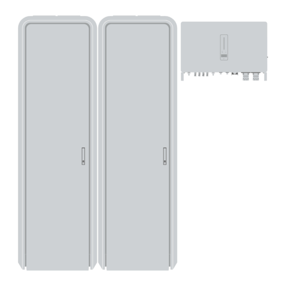
2.3 Product introduction Component list Picture Item Content Size(mm) W:800 Inverter Inverter D300 H:620 W:640 D:870 Cabinet Cabinet Frame H:2109 W:445 Battery Module Battery Module D:738 H:95 W:448 Master BMS Master BMS D:695 Module Module H:188 W:448 Sub-Master BMS Sub-Master BMS D:695 Module Module... -
Page 18: Inverter
2.3.1 Inverter The Wattsonic WTS-[25-50kW]-100A-3P series inverter is also known as a hybrid inverter or storage inverter, which is mainly used to combine the PV array, lithium battery, loads, and power grid to realize intelligent power management and dispatching. The WTS-[25-50kW]-100A-3P series hybrid inverter includes 7 models, which are listed below:... -
Page 19: Battery Module
Communication RS485 or CAN. Indicator The inverter isn’t communicating Orange Always on with Wattsonic smart meter. The inverter isn’t communicating Always on with the BMS. Display Display off to save power, press the button to wake up the display. Button Switch display information and set parameters by short press or long press. -
Page 20: Master & Sub-Master Bms
2.3.3 Master & Sub-Master BMS The battery management unit of the rack has a built-in Rack BMS and battery protection Unit. Mounted in the uppermost position of the cabinet. Use 1*sub-master BMS for a single cabinet system. Use 1*master BMS and (n-1)*sub-master BMS for a n*cabinet system. WiFi port Connect with external antenna Multi-function communication connector: RS485/CAN/DRED... -
Page 21: Cabinet Frame
1) The device is thoroughly tested and strictly inspected before delivery. Nonetheless, damage may still occur during shipping. For this reason, please conduct a thorough inspection after receiving the device. 2) Contact Wattsonic or the transport company in case of any damage or incompleteness, and provide photos to facilitate services. -
Page 22: Product Installation
Product Installation 3.1. Installation tool Caution: All tools used for installing the battery should be insulated or free of exposed metal parts. If not, at least the handle knob must be insulated. (1) Torque wrench Used for fastening the cable terminal and product. (2) Electric driver Used to fasten the enclosure of a product. - Page 23 Cabinet packing list Cabinet frame Master BMS module Battery module L type mounting structure Sub-master BMS module M4×10 triad screw Break the paint gasket Positive/ negative power cable M6×60 expansion bolt Com resistor External antenna Placeholder relay socket (optional) Communication cable PE terminal User Manual...
-
Page 24: Supported Installation Environment
3.3 Supported installation environment 3.3.1 Installation location of inverter The Wattsonic WTS-[25-50kW]-100A-3P series inverters are designed with IP65 protection enclosure for indoor and outdoor installations. When selecting an inverter installation location, the following factors should be considered: The wall on which the inverters mounted must be able to withstand the weight of the inverter. -
Page 25: Commercial Cabinet Installation
3.4 Commercial cabinet installation 3.4.1 Installation preparation Choice of installation position Recommended installation space of single rack / multiple racks: Minimum 500mm open space Minimum Minimum Minimum 2000mm 2000mm 2000mm open space open space open space Pre-installation check Before proceeding with the installation, pre-check the battery to make sure it is safe. Use a digital multimeter to measure the voltage between the positive terminal (+) and the negative terminal (-) of the battery module. -
Page 26: Single Cabinet Installation
3.4.2 Single cabinet installation (1) Rack installation and fixing Refer to the construction drawing to install the cabinet. Step 1: Place the cabinet on a level stable floor. Step 2: The cabinet can be adjusted as needed from the back wall, and matched with the equidistant holes of the L type mounting structure, and fixed. - Page 27 (2) Mounting and securing product Caution: Please use at least 3-4 people during installation for safety reasons. Do not mount the module upside down. Check the module before installation to ensure safety. Step 1: Open the cabinet door and put the battery modules one by one into the cabinet until a “click” sounds. User Manual...
- Page 28 Step 2: Fix the battery modules to the cabinet with 4 M4×10 triad screws on both sides after putting them into the cabinet. And put a break paint gasket in the paint gasket between each triad screw and module, as shown above, to enhance the electrical conductivity of the whole cabinet.
-
Page 29: Multi-Cabinet Installation
3.4.3 Multi-cabinet installation (1) Rack installation and fixing Refer to the construction drawing to install the cabinet. Step 1: Place the cabinet on a level stable. Step 2: The cabinet can be adjusted as needed from the back wall, and matched with the equidistant holes of the L type mounting structure, and fixed. - Page 30 (2) Mounting and securing product Caution: For safety reasons, please use at least 3-4 people during installation. Do not mount the module upside down. Check the module before installation to ensure safety. Step 1: Open the cabinet door and put the battery modules one by one into the cabinet until a “click” sounds. Please install the battery from the bottom to the top for safety reasons.
- Page 31 Step 2: Fix the battery modules to the cabinet with 4 M4×10 triad screws on both sides after putting them into the cabinet. And put a break paint gasket in the paint gasket between each triad screw and module, as shown above, to enhance the electrical conductivity of the whole cabinet.
-
Page 32: Inverter Installation
3.5 Inverter installation 3.5.1 Installation preparation Installation spacing Reserve enough clearance around the inverter to ensure sufficient space for heat dissipation. ≥300mm ≥600mm ≥600mm ≥450mm In case of multiple inverters, reserve specific clearance between the inverters. ≥600mm ≥600mm ≥600mm ≥600mm When installing inverters back-to-back, the distance between every two inverters should be at least 600 mm. - Page 33 Installation angle Install the inverter vertically. Never install the inverter horizontally, or at forward/backward tilted, or upside down. User Manual...
-
Page 34: Mounting The Inverter
3.5.2 Mounting the inverter Bracket installation Dimensions of wall bracket (mm) 4- 12 1) Level the assembled inverter-bracket by using the level, and mark the positions for drilling holes on the mounting bracket. Drill the holes by using a hammer drill. 2) Secure the inverter-bracket with bolts. -
Page 35: Electrical Connection
Warning: Static may cause damage to the electronic components of the inverter. Anti-static measures should be taken during installation and maintenance. Note: Do not use other brands or terminals other than the terminals in the accessory package. Wattsonic has the right to refuse all damages caused by the mixed-use of terminals. - Page 36 (2) Ground terminal connection of single cabinet After the cabinet is fixed, connect one of the earth points of the cabinet (side top or bottom) to the PE distribution box. (3) Ground terminal connection of multi cabinet After the cabinet is fixed, connect one of the earth points of each cabinet (side top or bottom) to the PE distribution box. And each cabinet should be connected with a grounding wire.
-
Page 37: Connection Between Bms And Inverter
4 . 2 Connection between BMS and inverter 4.2.1 Single cabinet COM1 BACK-UP ON-GRID DC SWITCH 1-2 DC SWITCH 3-4 BAT+ BAT- COM2 Positive Power Cable Negative Power Cable Communication Cable Note: To ensure the safe use of the equipment, please connect the circuit breaker between the PC and the BMS. - Page 38 2) Communication Cable All communication ports are in the multifunction communication port at the front of BMS, including CAN port, 485 port, EMS port, and DRED port. Terminal definition details are listed below. Connect the Parallel COM of the mutifunction communication port to the inverter BMS COM port. Parellel COM Inverter/Parellel COM Inverter...
- Page 39 3) Placeholder relay socket (optional) When the number of battery modules in each cabinet is less than 17, please insert the placeholder relay socket in each empty position where the battery modules are not installed to guarantee that the product operates normally. Note: The batteries placed in each commercial cabinet must be more than 10.
-
Page 40: Multiple Cabinets
4.2.2 Multiple cabinets COM1 BACK-UP ON-GRID Combiner DC SWITCH 1-2 DC SWITCH 3-4 BAT+ BAT- COM2 Positive Power Cable Negative Power Cable Communication Cable Note: To ensure the safe use of the equipment, please connect the circuit breaker between the PC and the BMS. - Page 41 1) Power Cable As the figure below shows, when using more than one single cabinet for your system, please use a DC combiner box to connect between cabinets and inverter. 2) Communication Cable All communication ports are in the multifunction communication port at the front of BMS, including CAN port, 485 port, 485 port, EMS port, and DRED port.
-
Page 42: Electrical Wiring Diagram
4.3 Electrical wiring diagram This diagram shows Wattsonic WTS 25-50K series hybrid inverter wiring structure and composition, concerning the actural project, the installation and wiring have to be in line with the local standards. AC Breaker AC Breaker AC Breaker... - Page 43 Single inverter wiring diagram This diagram is an example without a special requirement for an electrical wiring connection. The neutral line of AC supply can be isolated or switched. BACK-UP ON-GRID 1(L1) 2(L2) 3(L3) 4(N) 12(L) 13(N) 5(L1-S1) 6(L1-S2) 7(L2-S1) 8(L2-S2) 9(L3-S1) 10(L3-S2)
- Page 44 This diagram is an example of Australia and New Zealand. The neutral line of the AC supply must not be isolated or switched, and the neutral cable of the GRID side and BACK-UP side must be connected according to the wiring rules AS/NZS_3000.
-
Page 45: Ac Connection
Max to ensure that the WTS 25-50K can safely disconnect itself from the power grid when an exception occurs. Input (output) current of WTS 25-50K AC side. The allowable AC cable of wire diameter and cross-sectional area for Wattsonic WTS 25-50K are as shown in the following:... -
Page 46: Installing The Ac Connector
4.4.2 Installing the AC connector Danger: High voltage may be present in the inverter! Ensure all cables are voltage-free before electrical connection. Do not connect the AC circuit breaker until all inverter electrical connections are completed. The AC terminal block is on the bottom side of the inverter. 1) Seal accessory option. -
Page 47: Removal The Ac Connector
Warning: The cord end terminals must be locked tightly and ensure they won’t be loose after a long period of use. 5) Insert the main body into the rubber core and hear the "click" sound, then tighten the nut with an open-ended wrench (torque 10.0±0.1N·m) and complete the installation with a "click, click, click."... -
Page 48: Monitoring Device Installation
The current Transformer, also called CT, is usually installed on the L wires between the house loads and the power grid. The Meter can be installed in the AC combiner box or other places that are unable to be touched by children. Wattsonic CT cable with a length of 2m is fixed and can not be extended. -
Page 49: Communication Connection
Notice: CT installation directions should strictly follow the instructions in the user manual. Otherwise, the inverter may not be working. The CT has to correspond with the port in the Meter, and the connection between the CT and the Meter needs to be reliable. -
Page 50: Assembling The Multi-Com Connector
Definition Function RJ45-1 Communicate with Meter RS 485 RJ45-2 Communicate with BMS Multifunction Relay NO (Normally Open) Reserved Reserved DRM4/8 DRM3/7 DRM2/6 DRED DRM1/5 For Australia and New Zealand COM D/0 REF D/0 Fast stop + Fast stop Fast stop - 485 B1 485 A1 CANL_P... -
Page 51: Connect The Meter And Bms Communication Cables
3) Remove the seal and lead the cable through the cable gland. 4.7.2 Connect the Meter and BMS communication cables Note: The communication between the meter/BMS and inverter is the RJ45 interface cable. The communication cable of the meter is 10M, and the line of BMS is 3M. 1) Thread the RJ45 plug of appropriate length through the swivel nut, and insert it into the open side of the rubber gasket. -
Page 52: Connect Other Cables
4.7.3 Connect other cables 1) Thread the cable of appropriate length through the swivel nut and the housing. Remove the cable jacket and strip the wire insulation. Wire Diameter r 4-6.5mm Cross-sectional Area 0.5~1.5mm 55mm 2) (Optional) When using a multi-core, multi-strand copper wire cable, connect the AC wire head to the cord end terminal (hand-tight). -
Page 53: Installing The Com Connector
Note: Before purchasing the battery, you need to ensure the battery you selected is in the battery approval list of Wattsonic; otherwise, the system may not work correctly. If you are unsure, don't hesitate to contact your installer or Wattsonic service team for confirmation. -
Page 54: Ems Communication
Note: The AC contactor should be placed between the inverter and the loads. Do not connect the load to the DO port directly. The Wattsonic does not supply the contractor. Connect the load to the DO port of the inverter directly if the load is designed with a DI port. -
Page 55: Parallel System
The on-grid and back-up side cannot be The back-up side cannot be connected on- connected to and generator directly. grid side or grid. For advanced applications, please contact our after-sales department. Note: For more installation and setup information about parallel systems, please contact Wattsonic. User Manual... -
Page 56: Pv String Connection
4.8 PV string connection Danger: High voltage may be present in the inverter! Ensure all cables are voltage-free before performing electrical operations. Do not connect the DC switch and AC circuit breaker before finishing the electrical connection. Warning: When the inverter is connected to the battery, the maximum MPPT voltage and operating voltage is 900V. -
Page 57: Assembling The Pv Connector
4.8.2 Assembling the PV connector Warning: Before assembling the DC connector, ensure the cable polarity is correct. 1) Peel off the DC cable insulation sleeve for 7 mm. 2) Disassemble the connector in the accessory bag. 3) Insert the DC cable through the DC connector nut into the metal terminal and press the terminal with a professional crimping plier (pull back the cable with some power to check if the terminal is well connected to the cable). -
Page 58: Installing The Pv Connector
4.8.3 Installing the PV connector 1) Rotate the DC switch to the “OFF” position. 2) Check the cable connection of the PV string for polarity correctness and ensure that the open circuit voltage, in any case, does not exceed the inverter input limit of 1,000V. 630.0 +... -
Page 59: Commissioning And Maintenance
Warning: Please don't try to switch off Master BMS during regular charge and discharge, which has high risk to damage BMS inside core components. 5.1.3 Emergency stop function Wattsonic WTS 25-50K hybrid inverter comes standard with a fast stop function, and you can Emergency stop button... -
Page 60: Inverter Commissioning
7.3 Local configuration App". 2) Register an account on the Cloud monitoring App. If you have got the account and password from the distributor/ installer or Wattsonic, skip this step. 5.2.2 Inspection Check the following items before starting the inverter: 1) All equipment has been reliably installed. -
Page 61: Bms Commissioning
Note: SOC RESET FUNCTION When the inverter is turned on for the first time, the battery will be automatically charged to calibrate the battery SOC. After the battery is charged, this function will be turned off automatically (If you confirm that it is not necessary, you can manually turn off the function. -
Page 62: Maintenance
Caution: A temporary warning sign or barrier must be posted to keep non-related persons away while performing electrical connection and service work. Attention: For any maintenance need, please contact us. Otherwise, Wattsonic shall not be held liable for any damage caused. -
Page 63: Inverter Operation
Inverter operation When the inverter is turned on, the following interfaces will be displayed on the OLED display, and the OLED display allows the user to check various operation information and to modify the settings of the inverter. Note: If the parameter is a number short press to change the number, long press to confirm the number and jump to the next number. -
Page 64: General Setting
6.2 General Setting General Settings FM Version V1.xx.xx.xx.xx Check code System Info V1.00 xxxxxxxxxxxxxxx V1.xx.xx.xx.xx xxxxxx 2022-05-30 10:05:05 2022-05-30 10:05:05 2022-05-30 10:05:05 Fault Info Fault 1 Fault 2 Fault N RSSI <General> <General> <General> <General> DHCP Set DHCP Set IP Addr IP Addr 192.168.0.10 192.168.0.10... -
Page 65: Advanced Setting
6.3 Advanced Setting Advanced InPut Password Wait 1000 Settings Incorrect Verify Fail Wait Correct Verify OK <Advanced> <Advanced> <Advanced> <Advanced> The last page Safety Set Safety Set Safety Set Safety Set 50Hz Default Safety Code 1S afety Code 2S afety Code N <Advanced>... - Page 66 Previous Page <Advanced> <Advanced> <Advanced> OnGrid SOCProt OnGrid SOCProt OnGrid SOCProt <Advanced> <Advanced> OnGrid EndSOC OnGrid EndSOC 3 3 0 0 <Advanced> <Advanced> <Advanced> <Advanced> <Advanced> <Advanced> <Advanced> <Advanced> Unbalan.Output Unbalan.Output Unbalan.Output <Advanced> Auto Test CEI-021 <Advanced> <Advanced> <Advanced> <Advanced> System Maint.
- Page 67 Inverter Display Abbreviation and Complete Name Reference Table Abbreviation Complete Name Safety Set Select the code that meet local regulatory requirements Battery_ID Set Select the battery model Work Mode Current work mode / work mode setting Export Limit On-grid export limit function switch Feed in Grid Set the percentage of the power that is allowed to feed to the grid Reactive Modes...
-
Page 68: Country Code (Safety Code) Setting
Abbreviation Complete Name MaxOutputSet Select the maximum AC output power. Rated, Max. output power= Rated output power on the datasheet Overload, Max. output power= Max. output power on the datasheet Limit, Max. output power< Rated output power on the datasheet Export Control In the power export limit on mode, when the communication between the inverter and meter or the inverter and datalogger is interrupted, select the... - Page 69 Connect the AC cable, auto test will start after the inverter connected to the grid, see the operation steps below: Previous Page <Advanced> <Advanced> If Tested Auto Test Auto Test Wait CEI 0- 21 Record Wait <Advanced> Vac Set: 253.0V Time Set: 603 S Wait Wait...
-
Page 70: Reactive Power
6.6 Reactive Power Requirement Design freedom area 1,0 S in some countries 0,1 S +0,6 P -0,6 P Absorption of reactive energy Provision of reactive energy (under-excited) (over-excited) Capabilities Mode Descriptions The PF is fixed at +1.000. The reactive power can be regulated by the parameter PF (Power Factor). The reactive power can be regulated by the parameter fixed Q(in Pn%). -
Page 71: Q(P)" Mode
6.6.4 “Q(P)” Mode The PF of the inverter output varies in response to the output power of the inverter. “Q(P)” Mode Parameter Descriptions: Parameter Explanation Range QP_P1 Output power at P1 on the Q(P) mode curve (in percentage) 10% ~ 100% QP_P2 Output power at P2 on the Q(P) mode curve (in percentage) 20% ~ 100%... -
Page 72: Q(U)" Mode
6.6.5 “Q(U)” mode The reactive power output of the inverter will vary in response to the grid voltage. “Q (U)” Mode Parameter Descriptions: Parameter Explanation Range Hysteresis Ratio Voltage hysteresis ratio on the Q(U) mode curve 0 ~ 5% QU_V1 Grid voltage limit at P1 on the Q(U) mode curve 80% ~ 100% QU_Q1... -
Page 73: Monitoring
7.2 Cloud monitoring app Wattsonic inverter provides a monitoring port that can collect and transmit data from the inverter to the Wattsonic monitoring platform via an external monitoring device. Please refer to the product nameplate on the side of the enclosure to get the monitoring application. -
Page 74: Troubleshooting
Troubleshooting 8.1 Error message Wattsonic WTS-[25-50kW]-100A-3P series hybrid inverter is designed following grid operation standards and conforms to the requirements of safety and EMC. The inverter had passed rigorous tests to ensure it ran sustainably and reliably before shipment. When a fault occurs, the corresponding error message will be shown on the OLED display, and in this case, the inverter might stop feeding into the grid. - Page 75 Error Message Description Solution GFCI Fault The inverter detects that the 1. Restart the inverter. ground leakage current exceeds 2. Check whether the PV panels, cables, and the limitation. connectors are waterlogged or damaged. 3. Seek help from the installer or manufacture. PV Over Voltage Reduce the number of PV panels to make sure PV input voltage exceeds the...
- Page 76 Error Message Description Solution cable are in poor connection on ground connection is abnormal. AC side. 2. restart the inverter. 3. Seek help from the installer or manufacture. 1. Restart the inverter. Inverter's internal fan got failed Internal Fan Fault 2.
-
Page 77: Inverter Maintenance
Error Message Description Solution Inverter OC The load power exceeds the range 2. Check whether back-up side is short circuit. of its limit of inverter in off-gird mode SCI Fault Internal communication got failed. 1. Restart the inverter. Caused by a strong external 2. -
Page 78: Battery Maintenance
Note: Restart the inverter only after removing the fault that impairs safety performance. Never arbitrarily replace any internal components. For any maintenance support, please get in touch with Wattsonic. Otherwise, Wattsonic shall not be held liable for any damage caused. -
Page 79: Appendix
Appendix 9.1 Technical Parameters Module specification Sub-Master BMS Operation Voltage 150-1000V/ 700-1500V (Need to confirm upon order) Max. Charge/Discharge Current 100A Recommend Charge/Discharge Current 100A Pre-charge, Over-Less Voltage/ Over-Less Temperature Protection Functions Cells Balancing/ SOC-SOH calculationetc Communication Protocol/Connector Type CAN/RS485 ModBus, TCP/ IP/ RJ45/ WiFi/ LAN/ GPRS Power Connection Type Amphenol MC4 User Interface... - Page 80 Inverter specification Model WTS-25K-100 WTS-30K-100 PV Input Start-up voltage (V) Max. DC input voltage (V) 1000 1000 Rated DC input voltage (V) MPPT voltage range (V) 200-850 200-850 No. of MPP trackers No. of DC inputs per MPPT Max. input current (A) 30*4 30*4 Max.
- Page 81 Model WTS-25K-3P WTS-30K-3P Efficiency Max. efficiency 98.8% 98.8% European efficiency 98.3% 98.3% Protection DC reverse polarity protection Integrated Battery input reverse connection Integrated protection Integrated Insulation resistance protection Integrated Surge protection Integrated Over-temperature protection Integrated Residual current protection Integrated (Frequency shift) Islanding protection Integrated AC over-voltage protection...
- Page 82 Model WTS-36K-100 WTS-40K-100 Battery Side Battery type Lithium Battery (with BMS) Battery communication mode Battery voltage range (V) 135 - 750 135 - 750 Maximum charging current (A) Maximum discharge current (A) Grid Side Rated output power (kW) 36.0 40.0 Max.
- Page 83 Model WTS-36K-100 WTS-40K-100 General Data Over voltage category PV: 2 ; Main: 3 Dimensions (mm) 800*620*300 (W*H*D) Weight (KG) Protection degree IP65 Standby self-consumption (W) < 15 Topology Transformerless Operating Temperature Range (°C) - 30 ~ 60 Relative Humidity (%) 0 ~ 100 Operating Altitude (m) 3000 (>...
- Page 84 Model WTS-50K-100 WTS-40K-P-100 WTS-50K-100-P Back-up Side Rated output power (kW) 50.0 40.0 50.0 Max. output power (kW) 55.0 44.0 55.0 Rated output apparent power (kVA) 50.0 40.0 50.0 Max. output apparent power (kVA) 55.0 44.0 55.0 Rated output current (A) 75.0 60.0 75.0...
-
Page 85: Contact Information
Address: H1 NO.6 Jingxian Road, Xinwu District, Wuxi 214135, Jiangsu Province, China Website: www.wattsonic.com Service Mail: service@wattsonic.com * Wattsonic reserves the right to modify the technical datasheet and apperance of the product in the cataloge without prior advice to the users. User Manual...
Need help?
Do you have a question about the 25K-100A-3P and is the answer not in the manual?
Questions and answers