
Related Manuals for wattsonic 6.0K-25A-3P


Summary of Contents for wattsonic 6.0K-25A-3P
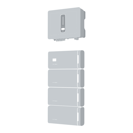
- Page 1 User Manual Wattsonic High Voltage Three Phase All-In-One ESS 4/5/6/8/10/12 KW-25A-3P | 10/12/15/20 KW-40A-3P Oct 2023...
- Page 3 Power your home, and you will power the planet.
-
Page 4: Table Of Contents
5.2.2 Specifications 5.2.3 BMS appearance 5.2.4 Battery appearance 5.2.5 Combiner boxappearance Introduction 5.3 Operation modes 2.1 What's wattsonic all-in-one ess 5.4 Back-up and off-grid output 5.6 Unpacking and storage Product Before Using Mechanical Installation 3.1 How to use this manual 6.1 Mounting the inverter... - Page 5 Screen Operation 7.4 Ac connection 7.4.1 Ac side requirements 9.1 Main window 7.4.2 Assembling the ac connector 9.2 General setting 7.4.3 Installing the ac connector 9.3 Advanced setting 7.5 Monitoring device installation 9.4 Country code (safety code) setting 7.6 Meter and CT connection 9.5 Auto-test 7.7 Communication connection 7.7.1 Assembling the Multi-Com connector...
-
Page 6: Overview
Overview To secure the full 10-year product warranty, be sure to install the Wattsonic Li-LV battery modules by qualified installers. Warning: Before installing or using the Wattsonic Li-LV LiFePO4 battery modules, read this document. Failure to do so or to follow any of the instructions or warnings in this document can result in electrical shock, serious injury, death, or damage to the Wattsonic Li-LV LiFePO4 battery modules, potentially rendering them unusable. -
Page 7: Introduction
Power when needed Wattsonic All-in-One ESS enables energy storage from solar panels during the day or from the grid when energy rates are low, discharges energy for backup or use at night, and automatically optimizes home energy. Wattsonic All-in-One ESS thereby maximizes solar consumption and reduces energy spending. -
Page 8: Supported Environment
3.3 Supported installation environment 3.3.1 Installation location of inverters 1. The wall on which the inverters are mounted must withstand the weight of the inverter. 2. The inverter needs to be installed in a well-ventilated environment. 3. Do not expose the inverter directly to strong sunlight to prevent excessive temperature operation. You can install the inverter in a place with shelter to avoid direct exposure to sunlight and rain. -
Page 9: Installation Angle
3.3.3 Installation angle Install the inverter vertically. Never install the inverter horizontally, at a forward or backward tilt, or upside down. Permitted and prohibited mounting positions Correct Wrong 3.3.4 Recommended installation spacing Reserve enough clearance around the inverter to ensure sufficient space for heat dissipation. Minimum 500mm to top space Minimum... -
Page 10: Disclaimer
3.4 Disclaimer Wuxi Wattsonic Energy Technology Co., Ltd. has the right not to undertake quality assurance in any of the following circumstances: 1) Damages caused by improper transportation 2) Damages caused by incorrect storage, installation, or use 3) Damages caused by the installation and use of equipment by non-professionals or untrained personnel... - Page 11 NOTE related. 1. Read this entire document before installing or using Wattsonic All-in-one ESS. Failure to do so or to follow any of the instructions or warnings in this document can result in electrical shock, serious injury, or death or can damage the Wattsonic LFP Battery, potentially rendering it inoperable.
- Page 12 5. Do not directly connect the Wattsonic LFP Battery to photovoltaic (PV) solar wiring. 6. When installing a Wattsonic LFP Battery in a garage or near vehicles, keep it out of the driving path. Install the Wattsonic LFP Battery on a side wall and/or above the height of vehicle bumpers.
-
Page 13: Description
The system is not suitable for supplying life-sustaining medical devices. It cannot guarantee backup power in all circumstances. The applicable grid types for the Wattsonic 4.0-20.0kW-3P series are TN-S, TN-C, TN-C-S, and TT. When applied to the TT grid, the voltage of N to PE suggests less than 30V. -
Page 14: Product Introduction
5.2 Product introduction The Wattsonic 4.0-20.0kW-3P series inverter is also known as a hybrid inverter or storage inverter, which is mainly used to combine the PV array, lithium battery, loads, and power grid to realize intelligent power management and dispatching. - Page 15 Communication RS485 or CAN. Indicator The inverter isn’t communicating Orange Always on with Wattsonic smart meter. The inverter isn’t communicating Always on with the BMS. Display Display off to save power, press the button to wake up the display. Button Switch display information and set parameters by short press or long press.
-
Page 16: Bms Appearance
5.2.3 BMS appearance Inverter WIFI Inverter/Parallel COM Parallel COM LAN COM Battery COM Battery Input Inverter WIFI Inverter/Parallel COM Parallel COM LAN COM Battery COM Battery Input 5.2.4 Battery appearance 5.2.5 Combiner box appearance Emergency Stop User Manual... -
Page 17: Operation Modes
5.3 Operation modes Wattsonic 4.0-20.0kW-3P series inverter has the following basic operation modes and you can configure the operation mode as per your preference in the App. General Mode Loads Inverter Battery Grid In this working mode, when the power from the PV array is sufficient, PV power will supply the loads, battery, and grid in the order of loads first, battery second, and grid last. - Page 18 Peak load Shifting (Load Shifting) Pload>Pmax Loads Inverter Battery Grid Set the maximum power Pmax (kVA) contracted with the grid. When the load consumption is less than the Pmax, the PV will charge the battery first, and the grid will supply the load.
- Page 19 UPS Mode Loads Inverter Battery Grid In this working mode, the inverter will use the power from PV or grid to charge the battery until it is fully charged, and as long as the grid is there, the battery won’t discharge. Back-up Loads Inverter Battery...
- Page 20 Economic Mode Loads Inverter Battery Grid In this working mode, you can set charge/discharge power and time in the App. The inverter will use the energy from PV or the grid (whether to use it or not can be set in the App) to charge the battery for a predetermined period. Loads Inverter Battery...
- Page 21 Off-Grid Mode, Loads Inverter Battery Grid In the purely t power from PV will supply the backup loads first and then charge the battery if there's surplus power. Loads Inverter Battery Grid When the power from PV isn’t enough, the battery will discharge to supply backup loads with PV. User Manual...
-
Page 22: Back-Up And Off-Grid Output
4) The device is thoroughly tested and strictly inspected before delivery. Nonetheless, damage may still occur during shipping. For this reason, please conduct a thorough inspection after receiving the device. 5) Contact Wattsonic or the transport company in case of any damage or incompleteness, and provide photos to facilitate services. -
Page 23: Mounting The Inverter
Product Mechanical Installation 6.1 Packing list The package of the whole system includes the following accessories. Please check whether the accessories in the packing box are complete when receiving the goods. Some accesssories are optional, need to comfirm upon order. Wall-mounting bracket , Expansion plug set, Inverter... - Page 24 Back Sheet Plastic Expansion Pipe and Self- Master BMS Module Battery Module tapping Screw(M4/M6) AIO KIT (Power+Com.+Earthing) Power Cable Battery<->Battery BMS<->Battery AIO KIT Terminal BMS<->Inverter COM Cable Parallel COM Cable BMS<->Inverter (Optional) COM Resistor Battery<->Battery BMS<->Inverter Stack Base(Optional) Stackable Fixed Bar& Frame(Optional) Earth cable User Manual...
-
Page 25: Mounting Batteries
6.2 Mounting products 6.2.1 Wall mounted (vertical) Suggested Inverter+Master BMS + Battery Modules Minimum 540mm Please use 7 pieces of back sheet expansion screws to fix the inverter’s back sheet to the wall. Minimum 390mm Minimum 265mm Please use 4 pieces battery back sheet expansion screws to fix the Master BMS and battery back sheet to the wall. -
Page 26: Wall Mounted (Vertical)
Mounting the inverter Lift up the inverter with both hands, hang the Fix the inverter to back rail on the back sheet carefully. the back sheet with a screw. Total height Total height 1276mm 1595mm One row of back sheet Two rows of back sheet Start the installation from the bottom, and complete the installation from bottom to top. -
Page 27: Battery Stack Mounted
6.2.2 Battery stack mounted Suggested Inverter+Master BMS + Battery Modules Place the stack base, stacked batteries and Master Check the installation environment to ensure the ground is level. Place the stack base on the ground, and ensure it is level and stable. Then, place the first battery on it with the cushion facing down, the remaining batteries and master control in sequence. - Page 28 Mounting the inverter Please use 7 pieces inverter back sheet expansion screws to fix the inverter back sheet to the wall. minimum 500mm Fix the inverter to the back sheet with a screw. 1) Use the back sheet as the template to mark the position of holes on the wall. Make sure the back sheet is in a horizontal position.
-
Page 29: Electrical Connection
Electrical Connection 7.1 Earth cables connection Please use standard earth connection cables(M4/2N.M.) to series connect Master BMS and inverter external ground port, then to the earth point in a distribution box. to achieve the purpose of grounding protection. Please always remember to wire the earth cables before wiring other cables. -
Page 30: Battery Cables Connection
1. Do not use other brands and types of terminals other than those included in the accessory package. Wattsonic has the right to refuse all damages caused by the mixed-use of terminals. 2. Moisture and dust can damage the inverter. Ensure the cable gland is securely tightened during installation. -
Page 31: Wall Mounted (Vertical) Of Multi-String System
7.2.2 Wall mounted (vertical) of multi-string system Please ensure the main switch of the inverter& BMS is OFF during installation to guarantee high voltage protection. Emergency Stop Inverter Inverter Inverter Inverter Inverter WIFI WIFI WIFI WIFI WIFI Inverter/Parallel COM Inverter/Parallel COM Inverter/Parallel COM Inverter/Parallel COM Inverter/Parallel COM... - Page 32 Power cable connection Inverter WIFI Inverter/Parallel COM Parallel COM LAN COM Battery COM Battery Input Right Left Using AIO kit to connect BMS& batteries of each string as the figure shows. Connect the Inverter port of each BMS to the Battery+ Battery- on the right side of the combiner box...
-
Page 33: Stack Mounted Of Single String System
7.2.3 Stack Mounted of single string system Please ensure the main switch of the inverter& BMS is OFF during installation to guarantee high voltage protection. Connect the BAT+ and BAT- port of the inverter and the inverter port of BMS by the power cable. Connect the lnverter/ Parallel COM... -
Page 34: Stack Mounted Of Multi-String System
7.2.4 Stack mounted of multi-string system Please ensure the main switch of the inverter& BMS is OFF during installation to guarantee high voltage protection. Emergency Stop User Manual... - Page 35 Power cable connection Inverter WIFI Inverter/Parallel COM Parallel COM LAN COM Battery COM Battery Input Right Left Using AIO kit to connect BMS& batteries of each string as the figure shows. Connect the Inverter port of each BMS to the Battery+ Battery- on the right side of the combiner box...
-
Page 36: Inverter Connection
7.3 Inverter connection 7.3.1 Electrical wiring diagram This diagram shows Wattsonic 4.0~20.0kW-3P series hybrid inverter wiring structure and composition, concerning the real project, the installation and wiring have to be in line with the local standards. AC Breaker AC Breaker... - Page 37 Single inverter wiring diagram This diagram is an example without a special requirement for an electrical wiring connection. The neutral line of AC supply can be isolated or switched. BACK-UP ON-GRID User Manual...
- Page 38 This diagram is an example of Australia and New Zealand. The neutral line of the AC supply must not be isolated or switched, and the neutral line of the GRID side and BACK-UP side must be connected according to the wiring rules AS/ NZS_3000.
-
Page 39: Ac Connection
3P can safely disconnect itself from the power grid when an exception occurs, select a proper overcurrent protection device in compliance with local power distribution regulations and Max. input (output) current of 4.0~20.0kW-3P AC side. The allowable AC cable of wire diameter and cross-sectional area for Wattsonic 4.0~20.0kW-3P are as shown in the following: Wire Diameter Cross-sectional ... -
Page 40: Assembling The Ac Connector
7.4.2 Assembling the AC connector The AC terminal block is on the bottom side of the inverter. a) Take the AC connector out of the accessory bag and disassemble it. Cable Gland Threaded Sleeve AC Terminal Head b) According to the figure, select an appropriate cable, peel the insulation sleeve of the AC cable off for 50mm, and peel off the end of 3L /PE / N wires for 8mm. -
Page 41: Installing The Ac Connector
d) According to the arrow direction, push the threaded sleeve to make it connected with the AC terminal head and then rotate the cable gland clockwise to lock it. 7.4.3 Installing the AC connector High voltage may be present in the inverter! Ensure all cables are voltage-free before electrical connection. Do not connect the AC circuit breaker until all inverter electrical connections are completed. -
Page 42: Monitoring Device Installation
Wattsonic CT cable with a length of 2m is fixed and can’t be extended. The CTs have been connected to the Wattsonic Meter when you received them, and you just need to follow the wiring diagram in the Meter to join the CT. -
Page 43: Communication Connection
CT installation direction and phase sequence should strictly follow the instructions in the user manual. Otherwise, the inverter may not be working. The CT has to correspond with the port in the Meter, and the connection between the CT and the Meter needs to be reliable. -
Page 44: Assembling The Multi-Com Connector
Definition Function RJ45-1 RS 485 Communicate with Meter RJ45-2 Communicate with BMS Multifunction Relay NO (Normally Open) Reserved Reserved DRM4/8 DRM3/7 DRM2/6 DRED DRM1/5 For Australia and New Zealand COM D/0 REF D/0 Fast stop + Fast stop Fast stop - 485 B1 485 A1 CANL_P... -
Page 45: Connect The Meter And Bms Communication Cables
2) Take out the terminal block. 3) Remove the seal and lead the cable through the cable gland. 7.7.2 Connect the Meter and BMS communication cables The communication between the meter/BMS and inverter is RJ45 interface cable. The communication cable of the meter is 10M, and the cable of BMS is 3M. 1) Thread the RJ45 plug of appropriate length through the swivel nut, and insert it into the open side of the rubber gasket. -
Page 46: Connect Other Cables
2) Insert one side of the RJ45 plug into the RJ45 port of the terminal block. 3) Insert another side of the communication cable into the meter RS485 port or BMS CAN port. 7.7.3 Connect other cables 1) Thread the cable of appropriate length through the swivel nut and the housing. Remove the cable jacket and strip the wire insulation. -
Page 47: Installing The Com Connector
Before purchasing the battery, you need to ensure the battery you selected is in the battery approval list of Wattsonic; otherwise, the system may not work correctly. Please get in touch with your installer or Wattsonic service team for confirmation if you’re unsure about it. -
Page 48: Ems Communication
EMS and inverter is RS485. 7.7.7 Dred DRED interface is specially reserved for Australia and New Zealand according to their safety regulation, and Wattsonic doesn’t provide the DRED device for the customer. There is a resistor between 15(COM D/0) and 16(REF D/0); do not move the resistor while wiring. - Page 49 The AC contactor should be placed between the inverter and the loads. Do not connect the load to DO port directly. The company of Wattsonic does not supply the contactor. Connect the load to the DO port of the inverter directly if the load is designed with a DI port.
-
Page 50: Parallel System
The on-grid and back-up side cannot be The back-up side cannot be connected on- connected to and generator directly. grid side or grid. For advanced applications, please contact our after-sales department. For more installation and setup information about parallel systems, please contact Wattsonic. User Manual... -
Page 51: Pv String Connection
7.8 Pv string connection High voltage may be present in the inverter! Ensure all cables are voltage-free before performing electrical operations. Do not connect the DC switch and AC circuit breaker before finishing the electrical connection. PV Max. Input voltage is 950V without battery or 850V with battery. Otherwise, the inverter will be waiting. For best practice, ensure PV modules of the same model and specifications are connected in each string. -
Page 52: Assembling The Pv Connector
7.8.2 Assembling the PV connector Before assembling the DC connector, make sure that the cable polarity is correct. 1) Peel off the DC cable insulation sleeve for 7 mm. 2) Disassemble the connector in the accessory bag. 3) Insert the DC cable through the DC connector nut into the metal terminal and press the terminal with a professional crimping plier (pull back the cable with some power to check if the terminal is well connected to the cable). -
Page 53: Installing The Pv Connector
7.7.3 Installing the PV connector 1) Rotate the DC switch to the “OFF” position. 2) Check the cable connection of the PV string for polarity correctness and ensure that the open circuit voltage, in any case, does not exceed the inverter input limit of 1,000V. The input voltage is 950V without a battery or 850V with a battery;... -
Page 54: The Power Cable Of The Battery Connection
If the conductor core of the battery cable is too small, which may cause poor contact between the terminal and the cable, please use the cable specified in the above table, or contact Wattsonic to purchase terminals of other specifications. - Page 55 3) Insert the battery cable through the battery connector nut into the metal terminal and press the terminal with a professional crimping plier (pull back the cable with some power to check if the terminal is well connected to the cable). 4) Insert the positive and negative cables into the corresponding positive and negative connectors, pull back the battery cable to ensure that the terminal is tightly attached in the connector.
-
Page 56: System Start And Stop
7.10 System start and stop 7.10.1 Start the system 1. Turn on the DC switch on the Master BMS. 2. Wait for more than 5 seconds. Wait 5S 3.Turn on the Wake Up switch . 4.The system starts successfully when the display shows correct system information, or the indicator light on the Master BMS is green. -
Page 57: Emergency Stop Function
7.10.3 Emergency stop function Wattsonic 4.0~20.0kW-3P hybrid inverter comes standard with an emergency stop function, and you can use this function by connecting an external switch to the fast stop interface if it is required in the installation place. The external switch isn't included in our accessory box. -
Page 58: App Preparation
Monitoring App and 8.3 Local Configuration App". 2) Register an account on the Cloud monitoring App. If you have the account and password from the distributor, installer, or Wattsonic, skip this step. 8.2 Inspection before commissioning Check the following items before starting the inverter: 1) All equipment has been reliably installed. - Page 59 2) Select the battery ID suitable for the battery that is installed. CT AUTO TEST FUNCTION Wattsonic hybrid inverter has the function of detecting the installation direction and phase sequence of CT. The system is installed, this function can be enabled on the APP for detection.
-
Page 60: Screen Operation
Screen Operation When the inverter is turned on, the following interfaces will be displayed on the OLED display, and the OLED display allows the user to check various operation information and modify the settings of the inverter. If the parameter is a number, short press to change the number, long press to confirm the number and jump to the next number. -
Page 61: General Setting
9.2 General setting General Settings FM Version V1.xx.xx.xx.xx Check code System Info V1.00 xxxxxxxxxxxxxxx V1.xx.xx.xx.xx xxxxxx 2022-05-30 10:05:05 2022-05-30 10:05:05 2022-05-30 10:05:05 Fault Info Fault 1 Fault 2 Fault N RSSI <General> <General> <General> <General> DHCP Set DHCP Set IP Addr IP Addr 192.168.0.10 192.168.0.10... - Page 62 Inverter Display Abbreviation and Complete Name Reference Table Abbreviation Complete Name System Info System information FM Version Firmware version Series number Fault Info Fault information RSSI Received signal strength indicator DHCP Set Enable or disable DHCP functionality IP Addr If DHCP is turned off, set the static IP address Gateway Addr If DHCP is turned off, set the Gateway IP address Subnet Mask...
-
Page 63: Advanced Setting
9.3 Advanced setting Advanced InPut Password Wait 1000 Settings Incorrect Verify Fail Wait Correct Verify OK <Advanced> <Advanced> <Advanced> <Advanced> The last page Safety Set Safety Set Safety Set Safety Set Safety Code 1S afety Code 2S afety Code N 50Hz Default <Advanced>... - Page 64 Previous Page <Advanced> <Advanced> <Advanced> OnGrid SOCProt OnGrid SOCProt OnGrid SOCProt <Advanced> <Advanced> OnGrid EndSOC OnGrid EndSOC 3 3 0 0 <Advanced> <Advanced> <Advanced> <Advanced> <Advanced> <Advanced> <Advanced> <Advanced> Unbalan.Output Unbalan.Output Unbalan.Output <Advanced> Auto Test CEI-021 <Advanced> <Advanced> <Advanced> <Advanced> System Maint.
- Page 65 Inverter Display Abbreviation and Complete Name Reference Table Abbreviation Complete Name Safety Set Select the code that meet local regulatory requirements Battery_ID Set Select the battery model Work Mode Current work mode / work mode setting Export Limit On-grid export limit function switch Feed in Grid Set the percentage of the power that is allowed to feed to the grid Reactive Modes...
-
Page 66: Country Code (Safety Code) Setting
Abbreviation Complete Name MaxOutputSet Select the maximum AC output power. Rated, Max. output power= Rated output power on the datasheet Overload, Max. output power= Max. output power on the datasheet Limit, Max. output power< Rated output power on the datasheet Export Control In the power export limit on mode, when the communication between the inverter and meter or the inverter and datalogger is interrupted, select the... - Page 67 Connect the AC cable, and auto test will start after the inverter is connected to the grid; see the operation steps below: Previous Page <Advanced> <Advanced> If Tested Auto Test Auto Test Wait CEI 0- 21 Record Wait <Advanced> Vac Set: 253.0V Time Set: 603 S Wait Wait...
-
Page 68: Reactive Power
(over-excited) This mode can be enabled via the configuration software. Some locations, such as the AU and DE markets, have it activated by default. For information on changing default setpoints, please contact Wattsonic Technical Support at service@wattsonic.com. Descriptions of reactive power regulation modes:... -
Page 69: Qt" Mode
9.6.3 “Qt” mode In Qt mode, system rated reactive power is fixed, and the system injects reactive power according to the delivered reactive power ratio. The setting range of the reactive power ratio is 0–60% or 0–60%, corresponding to the capacities of inductive and capacitive reactive power regulation, respectively. -
Page 70: Q(U)" Mode
9.6.5 “Q(u)” mode The reactive power output of the inverter will vary in response to the grid voltage. “Q (U)” Mode Parameter Descriptions: Parameter Explanation Range Hysteresis Ratio Voltage hysteresis ratio on the Q(U) mode curve 0 ~ 5% QU_V1 Grid voltage limit at P1 on the Q(U) mode curve 80% ~ 100% QU_Q1... -
Page 71: Monitoring Device
10.2 Cloud monitoring app Wattsonic inverter provides a monitoring port that can collect and transmit data from the inverter to the Wattsonic monitoring platform via an external monitoring device. Please refer to the product nameplate on the side of the enclosure to get the monitoring application. -
Page 72: Troubleshooting
Troubleshooting 11.1 Error message Grid operation standards design the Wattsonic 4.0–20.0 kW-3P series hybrid inverters to conform to the requirements of safety and EMC. The inverter had passed rigorous tests to ensure it ran sustainably and reliably before shipment. When a fault occurs, the corresponding error message will be shown on the OLED display, and in this case, the inverter might stop feeding into the grid. - Page 73 Error Message Description Solution GFCI Fault The inverter detects that the 1. Restart the inverter. ground leakage current exceeds 2. Check whether the PV panels, cables, and the limitation. connectors are waterlogged or damaged. 3. Seek help from the installer or manufacture. PV Over Volt¬age Reduce the number of PV panels to make sure PV input voltage exceeds the...
- Page 74 Error Message Description Solution cable are in poor connection on ground connection is abnormal. AC side. 2. restart the inverter. 3. Seek help from the installer or manufacture. 1. Restart the inverter. Inverter's internal fan got failed Internal Fan Fault 2.
-
Page 75: Inverter Maintenance
Error Message Description Solution Inverter OC The load power exceeds the range 2. Check whether back-up side is short circuit. of its limit of inverter in off-gird mode SCI Fault Internal communication got failed. 1. Restart the inverter. Caused by a strong external 2. -
Page 76: Battery Maintenance
Items Methods Period System clean heck the temperature and dust of Six months to a year (it depends on the dust the inverter. contents in air.) Clean the inverter enclosure if necessary. Check if the air inlet and outlet are normal. Check whether there is damage Electrical connection 6 months after commissioning and then... -
Page 77: Appendix
*Battery System Configuration Options[2.3kWh]: 230V/6.9kWh, 307V/9.2kWh, 384V/11.5kWh, 460V/13.8kWh, 537V/16.1kWh, 614V/18.4kWh. *Battery System Configuration Options[3.84kWh]: 230V/11.5kWh, 307V/15.3kWh, 384V/19.2kWh, 460V/23.0kWh, 537V/26.8kWh, 614V/30.7kWh. * Wattsonic reserves the right to modify the technical datasheet and apperance of the product in the cataloge without prior advice to the users. User Manual... -
Page 78: Inverter Datasheets
12.2 Inverter datasheets Model 4.0K-25A-3P 5.0K-25A-3P PV Input Start-up voltage (V) Max. DC input voltage (V)* 1000* 1000* Rated DC input voltage (V) MPPT voltage range (V)* 120-950* 120-950* No. of MPP trackers No. of DC inputs per MPPT 1 / 1 1 / 1 Max. - Page 79 Natural Convection Noise Level (dB) < 25 Display OLED & LED Communication CAN, RS485, WiFi/LAN (Optional) Model 6.0K-25A-3P 8.0K-25A-3P PV Input Start-up voltage (V) Max. DC input voltage (V)* 1000* 1000* Rated DC input voltage (V) MPPT voltage range (V)*...
- Page 80 Model 6.0K-25A-3P 8.0K-25A-3P Battery Side Battery type Lithium Battery (with BMS) Battery communication mode Battery voltage range (V) 135 - 750 135 - 750 Maximum charging current (A) Maximum discharge current (A) Grid Side Rated output power (kW) Max. output power (kW) Rated output apparent power (kVA) Max.
- Page 81 Model 6.0K-25A-3P 8.0K-25A-3P General Data Over voltage category PV: 2 ; Main: 3 Dimensions (mm) 534*418*210 (W*H*D) Weight (KG) Protection degree IP65 Standby self-consumption (W) < 15 Topology Transformerless Operating Temperature Range (°C) - 30 ~ 60 Relative Humidity (%)
- Page 82 Model 10K-25A-3P 12K-25A-3P Back-up Side Rated output power (kW) 10.0 12.0 Max. output power (kW) 11.0 13.2 Rated output apparent power (kVA) 10.0 12.0 Max. output apparent power (kVA) 11.0 13.2 Rated output current (A) 14.5 17.5 Max. output current (A) 16.5 20.0 UPS switching time...
- Page 83 Model 10K-40A-3P 12K-40A-3P PV Input Start-up voltage (V) Max. DC input voltage (V)* 1000* 1000* Rated DC input voltage (V) MPPT voltage range (V)* 200-950* 200-950* No. of MPP trackers No. of DC inputs per MPPT Max. input current (A) 30/30 30/30 Max.
- Page 84 Model 10K-40A-3P 12K-40A-3P Protection DC reverse polarity protection Integrated Battery input reverse connection Integrated protection Integrated Insulation resistance protection Integrated Surge protection Integrated Over-temperature protection Integrated Residual current protection Integrated (Frequency shift) Islanding protection Integrated AC over-voltage protection Integrated Overload protection Integrated AC short-circuit protection General Data...
- Page 85 Model 10K-40A-3P 12K-40A-3P Grid Side Rated output power (kW) 15.0 20.0 Max. output power (kW) 16.54) 22.0 Rated output apparent power (kVA) 15.0 20.0 Max. output apparent power (kVA) 16.55) 22.0 Max. input apparent power (kVA) 30.0 30.0 Max. charging power of battery (kW) 15.0 20.0 Rated AC voltage (V)
-
Page 86: Contact Information
*PV Max. Input voltage is 950V without battery, or 850V with battery, otherwise inverter will be waiting. *Wattsonic reserves the right to modify the technical datasheet and apperance of the product in the user manual without prior advice to the users.
Need help?
Do you have a question about the 6.0K-25A-3P and is the answer not in the manual?
Questions and answers