
Related Manuals for wattsonic 4.0KW-3P Series


Summary of Contents for wattsonic 4.0KW-3P Series
- Page 1 User Manual Wattsonic 4.0~20.0KW-3P Series 4/5/6/8/10/12K-25A-3P 10/12/15/20K-25A-3P...
-
Page 3: Table Of Contents
About This Manual ……………………………………… 1.1 Overview ………………………………………………………………………… 5 1.2 Important Safety Instructions ………………………………………………… 6 1.3 What is Wattsonic 4.0-20.0kW-3P Series …………………………………… 9 1.4 How to Use This Manual ……………………………………………………… 10 1.5 Target Groups ………………………………………………………………… 10 1.6 Symbols ………………………………………………………………………… 10 Safety Instructions ………………………………………... - Page 4 Commissioning ………………………………………… 7.1 App Preparation ……………………………………………………………… 63 7.2 Inspection before Commissioning …………………………………………… 63 7.3 Commissioning Procedure …………………………………………………… 63 7.4 Stop the Inverter ……………………………………………………………… 64 Screen Operation ……………………………………… 8.1 Main Window ………………………………………………………………… 8.2 General Setting ………………………………………………………………… 8.3 Advanced Setting ……………………………………………………………… 8.4 Country Code (Safety Code) Setting ……………………………………… 8.5 Auto-Test ………………………………………………………………………...
-
Page 5: About This Manual
All specifications and descriptions contained in this document are verified to be accurate at the time of printing. However, because continuous improvement is a goal at Wattsonic, we reserve the right to make product modifications at any time. The images provided in this document are for demonstration purposes only. -
Page 6: Important Safety Instructions
Wattsonic Certified Installers. Wattsonic assumes no liability for injury or property damage due to repairs attempted by unqualified individuals or a failure to properly follow these instructions. These warnings and cautions must be followed when using Wattsonic 4.0-20.0kW-3P Series. - Page 7 Caution: Do not place Wattsonic LFP Battery in a storage condition for more than one (1) month, or permit the electrical feed on the Wattsonic LFP Battery to be severed for more than one (1) month, without placing Wattsonic LFP Battery into a storage condition in accordance with Wattsonic’s storage specifications.
- Page 8 Wattsonic LFP Battery. Warning: Do not expose the Wattsonic LFP Battery to ambient temperatures above 60°C (140°F) or below -30°C (-22°F). Caution: Ensure that no water sources are above or near Wattsonic LFP Battery, including downspouts, sprinklers, or faucets.
-
Page 9: What Is Wattsonic 4.0-20.0Kw-3P Series
POWER WHEN NEEDED Wattsonic enables the storage of energy from solar panels during the day, or from the grid when energy rates are low; discharges energy for backup or use at night;... -
Page 10: How To Use This Manual
The products, services or features purchased are subject to the commercial contracts and terms of Wattsonic. All or part of the products, services or features described in this doc- ument may not be within the scope of purchase. This document serves only as a guide to use, and all statements, information and recommendations in this document do not consti- tute any express or implied guarantee. - Page 11 User Manual 4.0-20.0kW-3P Series Indicates a hazard with a low level of risk that, if not avoided, could result in minor or moderate injury. CAUTION Indicates a situation that, if not avoided, could result in equipment or property damage, data loss, equipment performance degradation. NOTICE Indicates additional information, emphasized contents or tips that may be helpful, e.g., to help you solve problems or save time.
-
Page 12: Safety Instructions
⑨ When wiring the lithium battery terminals, please disconnect the breaker or switch of the lithium battery in case of a physical injury caused by the high voltage. 2.2 Statement Wattsonic has the right not to undertake quality assurance in any of the following circum- stances: ① Damages caused by improper transportation. - Page 13 User Manual 4.0-20.0kW-3P Series ⑦ Damages caused by unauthorized disassembly, alteration of products or modification of software codes. ⑧ Damages caused by abnormal natural environment (force majeure, such as lightning, earthquake, fire, storm, etc.). ⑨ Any damages caused by the process of installation and operation which don't follow the local standards and regulations.
-
Page 14: Inverter Introduction
It cannot guarantee backup power in all circumstances. NOTICE The applicable grid types for the Wattsonic 4.0-20.0kW-3P Series are TN-S, TN-C, TN-C-S and TT. When applied to the TT grid, the voltage of N to PE suggests less than 30V. -
Page 15: Product Introduction
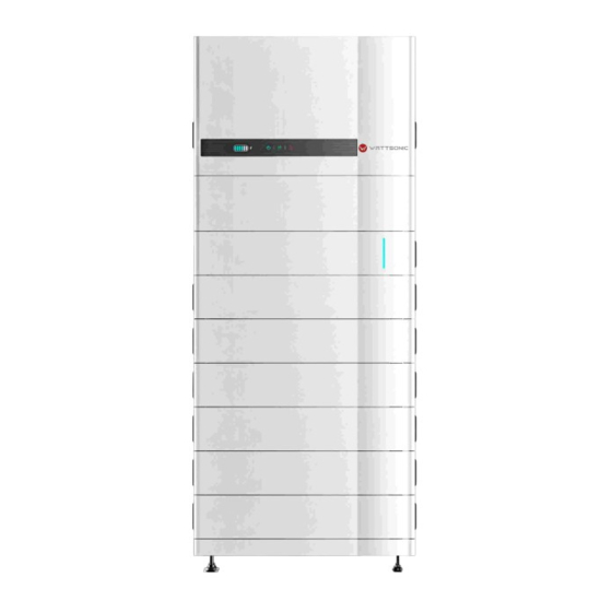
User Manual 4.0-20.0kW-3P Series 3.2 Product Introduction Wattsonic 4.0-20.0kW-3P Series inverter is also known as hybrid inverter or storage inverter, which is mainly used to combine the PV array, lithium battery, loads and power grid to realize intelligent power management and dispatching. - Page 16 User Manual 4.0-20.0kW-3P Series 3.2.3 Display Interface Power Indicator Display Grid Indicator Battery SOC and Status Indicator Alarm Indicator Button Item Indicator Status Description Battery not connected or communication fault. Battery is discharging or waiting, indicator shows battery Battery SOC and Always on SOC.
-
Page 17: Symbols On The Inverter
User Manual 4.0-20.0kW-3P Series 3.3 Symbols on the Inverter Symbol Description To avoid the potential effects on the environment and human health as a result of the presence of hazardous substances in electrical and electronic equipment, end-users of electrical and electronic equipment should understand the meaning of the crossed-out wheeled bin symbol. -
Page 18: Operation Modes
User Manual 4.0-20.0kW-3P Series 3.4 Operation Modes Wattsonic 4.0-20.0kW-3P Series inverter has the following basic operation modes and you can configure the operation mode as per your preference in the App. General Mode Loads In this working mode, when the power from the PV array is sufficient, PV power will supply the loads, battery, and grid in the order of ... - Page 19 User Manual 4.0-20.0kW-3P Series Peak load Shifting (Load Shifting) Loads Set the maximum power Pmax (kVA) contract- ed with the grid. When the load consumption is less than the Pmax, the PV will charge the battery first, and the grid supplies the load. When the battery is full, PV will supply the load together with the grid, but the battery doesn't.
- Page 20 User Manual 4.0-20.0kW-3P Series UPS Mode Loads In this working mode, the inverter will use the power from PV or grid to charge the battery until it is fully charged, and as long as the grid is there, the battery won’t discharge. Grid Back-up Loads When the grid fails, power from PV and battery...
- Page 21 User Manual 4.0-20.0kW-3P Series Economic Mode Loads In this working mode, you can set charge/dis- charge power and time in the App, inverter will use the power from PV or grid (whether to use can be set in the App) to charge the battery in the predetermined period.
- Page 22 User Manual 4.0-20.0kW-3P Series Off-grid Mode Back-up Loads In the purely off-grid mode, power from PV will supply the back-up loads first and then charge the battery if there's surplus power. No Grid Back-up Load When the power from PV isn’t enough, the battery will discharge to supply back-up loads together with PV.
-
Page 23: Back-Up And Off-Grid Output
④ Due to the condition of the battery itself, battery current might be limited by some fac- tors, including but not limited to the temperature and weather. Wattsonic 4.0-20.0kW-3P Series overloading ability in off-grid work mode describes as fol- lows:... -
Page 24: Unpacking And Storage
For this reason, please conduct a thorough inspection after receiving the device. Contact Wattsonic or the transport company in case of any damage or incompleteness, and provide photos to facilitate services. 3.6.1 Packing List The package of the inverter includes the following accessories. - Page 25 User Manual 4.0-20.0kW-3P Series User Manual Figure 3-5 Packing list Item Name and Quantity NOTE Inverter (1pcs) Wall-mounting bracket (1pcs), Expansion plug set (5pcs), M5 screws (1pcs) On-grid connector set (1pcs) Back-up connector set (1pcs) Black PV terminal (4.0K-25A-3P 2 pairs / 10K-40A-3P 4 pairs) Black Battery terminal (1pairs) Blue...
-
Page 26: Battery Introduction
User Manual 4.0-20.0kW-3P Series Battery Introduction 4.1 Appearance Introduction ① ② ③ ④ ⑤ ⑥ Left side Front ⑦ ⑧ 356mm 698mm Bottom ⑩ ⑪ ⑨ ⑫ ⑬ Sub-Master BMS ① Inverter positioner ② Inverter COM ③ Service COM ④ Earth point ⑤... - Page 27 User Manual 4.0-20.0kW-3P Series ① ② ③ ④ ⑤ ⑥ ⑦ ⑧ ⑨ Front Right side ⑩ 698mm 356mm Bottom ⑪ ⑫ ⑬ ⑭ ⑮ Battery module ① Battery positioner plug ② Terminal positioner plug ③ Earth cable ④ BMU Power Supply - ⑤...
- Page 28 User Manual 4.0-20.0kW-3P Series ① ② ③ ④ ⑤ ⑥ ⑦ 698mm 356mm Base module ① Battery positioner plug ② Terminal positioner plug ③ Earth cable ④ CAN COM Resistor(Pre-installed) ⑤ CAN COM Resistor(Pre-installed) ⑥ Battery Positive B+ ⑦ Battery Positive B+...
-
Page 29: Specifications
Hard Connection with Positioner Warranty 10000 Cycles within 10 Years Guarantee *Battery Systems Configuration Options: 230V/11.5kWh, 307V/15.3kWh, 384V/19.2kWh, 460V/23.0kWh, 537V/26.8kWh,614V/30.7kWh. *Wattsonic reserves the right to modify the technical datasheet and apperance of the product in the manual without prior advice to the users. -
Page 30: Standard Packing List
User Manual 4.0-20.0kW-3P Series 4.3 Standard Packing List Main units Sub-Master BMS for 3.84KWH 3.84KWH Li-HV LFP Battery Modules (Stackable) Base for Stackable Li-HV all-in-one system Standard Accessories 300MM Communication Cables from Master BMS to Inverter Grounding Wire 300mm from Master BMS to Inverter 300MM Positive Power Cables from Master BMS to Inverter 300MM Negative Power Cables from Master BMS to Inverter M6 Plastic Expansion Pipe and Self-tapping Screw Kit for Wall Mounted... -
Page 31: Mechanical Installation
User Manual 4.0-20.0kW-3P Series Mechanical Installation 5.1 Selection of Installation Location The wall on which the inverter is mounted must be strong and can withstand the weight of the inverter for a long time. The inverter needs to be installed in a well-ventilated environment. Do not expose the inverter directly to strong sunlight to prevent the power derat- ing due to excessive temperature. -
Page 32: General Installation Procedure
User Manual 4.0-20.0kW-3P Series 5.2 General Installation Procedure Installation procedure summary 1.Install the base; 2.Install the battery module and Sub-Master BMS; 3.Install the inverter; 4.Cables connection; 5.Install the cables cover and wall mounting support. System component ① ② ③ ④ ⑤... - Page 33 User Manual 4.0-20.0kW-3P Series Step1 Install the base Check the installation environment to ensure ground level. Place the base on the ground, and make sure it is level and stable. Step2 Install the battery module and Sub-Master BMS After the base is installed, the remaining battery and Sub-Master BMS are then placed in turn.
- Page 34 User Manual 4.0-20.0kW-3P Series Step3 Install the Inverter After the inverter is installed to the All-in-One Kit, put the All-in-One Kit to the stacked battery and Sub-Master BMS. Step4 Install the Kit for wall mounted and cables cover Monuting the kit for wall mounted, and tighten them with M6 plastic expansion pipes and self-tapping screws and screws.
- Page 35 User Manual 4.0-20.0kW-3P Series 5.3 Cables Connection After mechanical installation is finished, there are positive power line, negative power line, communication cable and earth cable between inverter and Sub-Master BMS need to be connected. The picture on this page shows the cables connection. Please follow the instruction and make sure all the cables are connected correctly.
-
Page 36: Electrical Connection
WARNING maintenance. Do not use other brands or other types of terminals other than the terminals in the accessory package. Wattsonic has the right to refuse NOTICE all damages caused by the mixed-use of terminals. Moisture and dust can damage the inverter, ensure the cable gland is securely tightened during installation. -
Page 37: Electrical Wiring Diagram
User Manual 4.0-20.0kW-3P Series 6.1 Electrical wiring diagram This diagram shows Wattsonic 4.0-20.0kW-3P Series wiring structure and composition, concerning the real project, the installation and wiring have to be in line with the local standards. AC Breaker AC Breaker AC Breaker... - Page 38 User Manual 4.0-20.0kW-3P Series Single inverter wiring diagram This diagram is an example without special requirement on electrical wiring connection. Neutral line of AC supply can be isolated or switched. BACK-UP ON-GRID 1(L1) 2(L2) 3(L3) 4(N) 5(L1-S1) 6(L1-S2) 7(L2-S1) 8(L2-S2) 9(L3-S1) 10(L3-S2) Figure 5-2 Standard wiring diagram...
- Page 39 User Manual 4.0-20.0kW-3P Series This diagram is an example for Australia and New Zealand. Neutral line of AC supply must not be isolated or switched, and the neutral line of GRID side and BACK-UP side must be connected together according to the wiring rules AS/NZS_3000. Otherwise, BACK-UP func- tion will not work.
-
Page 40: Ac Connection
② Before making the connection of AC cable, please confirm all DC & AC power source are disconnected from the inverter. ③ The Wattsonic 4.0-20.0kW-3P Series three-phase high voltage NOTICE hybrid inverter applies to the three-phase power grid with a voltage of 230/400V and a frequency of 50/60Hz. - Page 41 User Manual 4.0-20.0kW-3P Series Residual Current Monitoring Device With an integrated universal current-sensitive residual current monitoring unit included, the inverter will disconnect immediately from the mains power once a fault current with a value exceeding the limit is detected. However, if an external residual current device (RCD) is mandatory, the switch must be triggered at a residual current of 300 mA (recommended), or it can be set to other values according to local regulations.
- Page 42 User Manual 4.0-20.0kW-3P Series The cord end terminals must be locked tightly, and make sure it won’t be loose after a long period of use. WARNING ④ According to the arrow direction push the threaded sleeve to make it connected with the AC terminal head and then rotate the cable gland clockwise to lock it.
-
Page 43: Monitoring Device Installation
CAUTION 6.3 Monitoring Device Installation Wattsonic 4.0-20.0kW-3P Series supports WIFI, LAN, and 4G communication.Plug the WIFI, LAN, or 4G module into the COM1 port in the bottom of inverter. A slight "click" sound during the installation represents that the assembly is in place. -
Page 44: Meter And Ct Connection
The Meter can be installed in the AC combiner box or other places that are unable to be touched by children. Wattsonic CT cable with length of 2m, it’s fixed and can’t be extend- The CTs have been connected to the Wattsonic Meter when you received them, and you... -
Page 45: Communication Connection
User Manual 4.0-20.0kW-3P Series Meter terminals definition as shown in table below: Definition Function L1-S1 L1-S2 L2-S1 To detect the CT current L2-S2 L3-S1 L3-S2 L1/L2/L3/N connect to grid to detect power grid voltage Power supplied from grid RS485 RS485 Communicate with inverter 6.5 Communication Connection All communication ports are in the multifunction communication Port at the bottom of... - Page 46 User Manual 4.0-20.0kW-3P Series Definition Function RJ45-1 RS 485 Communicate with Meter RJ45-2 Communicate with BMS Multifunction Relay NO (Normally Open) Reserved Reserved DRM4/8 DRM3/7 DRM2/6 DRED For Australia and New Zealand DRM1/5 COM D/0 REF D/0 Fast stop + Fast stop Fast stop - 485 B1...
- Page 47 User Manual 4.0-20.0kW-3P Series ② Take out the terminal block. Figure 5-14 ② Remove the seal and lead the cable through the cable gland. Figure 5-15 6.5.2 Connect the Meter and BMS communication cables The communication between meter/BMS and inverter is RJ45 interface cable.
- Page 48 User Manual 4.0-20.0kW-3P Series ② Insert one side of the RJ45 plug into the RJ45 port of terminal block. Figure 5-17 ③ Insert another side of the communication cable into the meter RS485 port or BMS CAN port. 6.5.3 Connect other cables ①...
- Page 49 User Manual 4.0-20.0kW-3P Series Figure 5-19 ③ Fix all the wires to the terminal plug according to the assignment and tighten to a torque of 1.2+/-0.1N·m with a screwdriver. Figure 5-20 ④ Pull the wires outward to check whether they are firmly installed. Insert the terminal block into the connector until it snaps into place with an audible click.
- Page 50 User Manual 4.0-20.0kW-3P Series ⑤ Fasten the swivel nut. ・m 2.5+/-0.1N·m Figure 5-22 6.5.4 Installing the COM Connector ① Remove the waterproof lid from the COM terminal. ② Insert the COM connector into COM terminal on the bottom of the inverter until there is an audible click.
- Page 51 6.5.5 Meter and BMS communication Before purchasing the battery, you need to make sure the battery you selected is in the battery approval list of Wattsonic, otherwise, the system may not work properly. Please contact your installer or Wattsonic NOTE service team for confirmation if you’re not sure about it.
- Page 52 Maximum voltage and current at DO dry contact port: 230VAC 1A/ 30VDC 1A. NOTICE For more installation and setup information, please contact Wattsonic. NOTE Load Control Breaker Contactor...
- Page 53 The AC contactor should be placed between the inverter and the loads. Do not connect the load to DO port directly. The contactor is not supplied by the Wattsonic. Connect the load to the DO port of the inverter directly if the load is designed with a DI NOTE port.
- Page 54 The back-up side cannot be connected on- connected to and generator directly. grid side or grid. For advanced applications, please contact our after-sales department. Figure 5-27 For more installation and setup information about parallel system, please contact Wattsonic . NOTE...
-
Page 55: Pv String Connection
User Manual 4.0-20.0kW-3P Series 6.5.10 Fast stop Wattsonic 4.0-20.0kW-3P Series comes standard with fast stop function, and you can use this function by connecting an external switch into the fast stop interface if it requires in the installation place. The external switch doesn't include in our accessory box. - Page 56 ② The DC switch has to be certified by AS 60947.3:2018 and AS/NZS IEC 60947.1:2020 in Australia and New Zealand market. The Max. current of the DC switch matched by Wattsonic 4.0-20.0kW-3P Series is no less than 40A. We recommend the following electri-...
- Page 57 User Manual 4.0-20.0kW-3P Series ① Peel off the DC cable insulation sleeve for 7 mm. Figure 5-30 ② Disassemble the connector in the accessory bag. Figure 5-31 ③ Insert the DC cable through the DC connector nut into the metal terminal and press the terminal with a professional crimping plier (pull back the cable with some power to check if the terminal is well connected to the cable).
- Page 58 User Manual 4.0-20.0kW-3P Series Open-end Wrench Figure 5-33 6.6.3 Installing the PV Connector ① Rotate the DC switch to “OFF” position. Figure 5-34 ② Check the cable connection of the PV string for polarity correctness and ensure that the open circuit voltage in any case does not exceed the inverter input limit of 1,000V. Figure 5-35...
- Page 59 User Manual 4.0-20.0kW-3P Series ③ Insert the positive and negative connectors into the inverter DC input terminals respec- tively, a click sound should be heard if the terminals are well connected. Figure 5-36 ④ Seal the unused PV terminals with the terminal caps.
-
Page 60: Power Cable Of The Battery Connection
If the conductor core of the battery cable is too small, which may cause poor contact between the terminal and the cable, please use the cable specified in the above table, or contact Wattsonic to purchase CAUTION terminals of other specifications. - Page 61 User Manual 4.0-20.0kW-3P Series 10mm 10mm 10mm 10mm Figure 5-38 ③ Insert the battery cable through the battery connector nut into the metal terminal and press the terminal with a professional crimping plier (pull back the cable with some power to check if the terminal is well connected to the cable).
- Page 62 User Manual 4.0-20.0kW-3P Series ① Before making the battery connector, please make sure the polarity of the cable is correct. ② Use a multimeter to measure the voltage of the battery pack and WARNING make sure the voltage is within the inverter limitation and the polarity is correct.
-
Page 63: Commissioning
"8.2 Cloud monitoring App and 8.3 Local configuration App". ② Register an account on the Cloud monitoring App. If you have got the account and password from the distributor/installer or Wattsonic, skip this step. 7.2 Inspection before Commissioning Check the following items before starting the inverter: ①... -
Page 64: Stop The Inverter
② Select the battery ID suitable for the battery is installed. CT AUTO TEST FUNCTION Wattsonic 4.0-20.0kW-3P Series has the function of detecting the installation direction and phase sequence of CT. The system is installed, NOTE this function can be enabled on the APP for detection. -
Page 65: Screen Operation
User Manual 4.0-20.0kW-3P Series Screen Operation When the inverter is turned on, the following interfaces will be displayed on the OLED display, and the OLED display allows the user to check various operation information and to modify the settings of the inverter. If the parameter is a number short press to change the number, long press to confirm the number and jump to the next number. -
Page 66: General Setting
User Manual 4.0-20.0kW-3P Series 8.2 General Setting General Settings FM Version V1.xx.xx.xx.xx Check code System Info V1.00 xxxxxxxxxxxxxxx V1.xx.xx.xx.xx xxxxxx 2022-05-30 10:05:05 2022-05-30 10:05:05 2022-05-30 10:05:05 Fault Info Fault 1 Fault 2 Fault N RSSI <General> <General> <General> <General> IP Addr DHCP Set DHCP Set IP Addr... - Page 67 User Manual 4.0-20.0kW-3P Series Inverter Display Abbreviation and Complete Name Reference Table Abbreviation Complete Name System Info System information FM Version Firmware version Series number Fault Info Fault information RSSI Received signal strength indicator DHCP Set Enable or disable DHCP functionality IP Addr If DHCP is turned off, set the static IP address Gateway Addr...
-
Page 68: Advanced Setting
User Manual 4.0-20.0kW-3P Series 8.3 Advanced Setting Advanced InPut Password Wait Settings 1000 Incorrect Verify Fail Correct Verify OK <Advanced> <Advanced> <Advanced> <Advanced> The last page Safety Set Safety Set Safety Set Safety Set 50Hz Default Safety Code 1 Safety Code 2 Safety Code N <Advanced>... - Page 69 User Manual 4.0-20.0kW-3P Series Previous Page <Advanced> <Advanced> <Advanced> OnGrid SOCProt OnGrid SOCProt OnGrid SOCProt <Advanced> <Advanced> OnGrid EndSOC OnGrid EndSOC <Advanced> <Advanced> <Advanced> <Advanced> <Advanced> <Advanced> <Advanced> <Advanced> Unbalan.Output Unbalan.Output Unbalan.Output <Advanced> Auto Test CEI-021 <Advanced> <Advanced> <Advanced> <Advanced> System Maint.
- Page 70 User Manual 4.0-20.0kW-3P Series Inverter Display Abbreviation and Complete Name Reference Table Abbreviation Complete Name Safety Set Select the code that meet local regulatory requirements Battery_ID Set Select the battery model Work Mode Current work mode / work mode setting Export Limit On-grid export limit function switch Feed in Grid...
-
Page 71: Country Code (Safety Code) Setting
User Manual 4.0-20.0kW-3P Series Abbreviation Complete Name If turned it on, the battery will be automatically charged to calibrate the battery SOC Reset SOC. After the battery is charged, this function will be turned off automatically MPPT Parallel If MPPT is connected in parallel, enable this function. Select the maximum AC output power. - Page 72 User Manual 4.0-20.0kW-3P Series Connect the AC cable, auto test will start after the inverter connected to the grid, see the operation steps below: Previous Page <Advanced> <Advanced> If Tested Auto Test Auto Test Wait CEI 0- 21 Record Wait <Advanced>...
-
Page 73: Reactive Power
This mode can be enabled via configuration software. It is enabled by default in some regions, such as AU, DE market. For information on how to change default setpoints please contact Wattsonic Technical Support at service@wattsonic.com. Descriptions of reactive power regulation mode:... - Page 74 User Manual 4.0-20.0kW-3P Series 8.6.3 “Qt” Mode In the Qt mode, system rated reactive power is fixed, and the system injects reactive power according to the delivered reactive power ratio. The setting range of the reactive power ratio is 0~60% or 0~-60%, corresponding to the ranges of inductive and capacitive reactive power regulation respectively.
- Page 75 User Manual 4.0-20.0kW-3P Series 8.6.5 “Q(U)” Mode The reactive power output of the inverter will vary in response to the grid voltage. “Q(U)” Mode Parameter Descriptions: Parameter Explanation Range Hysteresis Ratio Voltage hysteresis ratio on the Q(U) mode curve 0 ~ 5% QU_V1 Grid voltage limit at P1 on the Q(U) mode curve 80% ~ 100%...
-
Page 76: Monitoring
User Manual 4.0-20.0kW-3P Series Monitoring 9.1 Monitoring Device Indicator Button Figure 8-1 Monitoring device display interface Indicator Status Description Connection abnormal Always On Communicate with the server normally The monitoring device is not connected to the router or is not connected to the base Slow flashing station. -
Page 77: Monitoring App
9.2 Cloud monitoring App Wattsonic inverter provides a monitoring port that can collect and transmit data from the inverter to Wattsonic monitoring platform via an external monitoring device. Please refer to the product nameplate on side of enclosure to get the monitoring application. If download issues exist, contact your dealer or Wattsonic technical support. - Page 78 User Manual 4.0-20.0kW-3P Series Warning: Please don't try to switch off Master BMS during regular charge and discharge, which has high risk to damage BMS inside core DANGER components.
-
Page 79: Troubleshooting
4.0-20.0kW-3P Series Troubleshooting 10.1 Error Message Wattsonic 4.0-20.0kW-3P Series is designed in accordance with grid operation standards, and conform to the requirements of safety and EMC. The inverter had passed a series of rigorous tests to ensure it runs sustainably and reliably before shipment. - Page 80 User Manual 4.0-20.0kW-3P Series Error Message Description Solution 1. Restart the inverter. 2. Check if the insulation of the wires in PV, GFCI Fault Excessive leakage current. battery, and AC is damaged. 3. Seek for help from the installer or manu- facture.
- Page 81 Neutral & ground cable are not connected on AC side or just occasional failure. well on AC side or restart inverter. 2. If the neutral & ground cable are con- nected well, please contact Wattsonic. 1. Restart the inverter. Internal Fan Fault Internal fan anomaly.
- Page 82 User Manual 4.0-20.0kW-3P Series Error Message Description Solution 1. Check whether the battery voltage ex- Bat OV Battery voltage is too high. ceeds the upper limit of the battery. 2. Check battery terminal wiring. 1. Restart the inverter. Backup OV Backup output voltage is too high.
- Page 83 User Manual 4.0-20.0kW-3P Series Error Message Description Solution 1. Restart the inverter. Inverter OC Backup output overcurrent. 2. Seek for help from the installer or manu- facture. 1. Restart the inverter. Phase Order Err phase sequence error. 2. Seek for help from the installer or manu- facture.
-
Page 84: Inverter Maintenance
NOTICE For any maintenance support, please contact Wattsonic. Otherwise, Wattsonic shall not be held liable for any damage caused. Servicing of the device in accordance with the manual should never be undertaken in the absence of proper tools, test equipment or the... -
Page 85: Battery Maintenance
User Manual 4.0-20.0kW-3P Series Items Methods Period heck the temperature and dust of the inverter. Six months to a year (it depends on System clean Clean the inverter enclosure if necessary. the dust contents in air.) Check if the air inlet and outlet are normal. Electrical Check whether there is damage to the cables, 6 months after commissioning and... -
Page 86: Contact Information
• Serial number of the device • Date of the device • Fault code/name • Brief description of the problem China (HQ) Wuxi Wattsonic Energy Technology Co., Ltd Address: No. 200 Linghu Road, Xinwu District, Wuxi 214100,Jiangsu Province, China Website: www.wattsonic.com Service Mail: service@wattsonic.com... - Page 87 www.wattsonic.com...
Need help?
Do you have a question about the 4.0KW-3P Series and is the answer not in the manual?
Questions and answers