Table of Contents
Advertisement
Publication 3-71
Issue 3.3 : 01/23
Installation, Operating and Maintenance Manual
Fridgewatch
4000 Controller Mk2
®
Software Version FW40Mk2P3.105 Onwards
This publication is applicable to the following
J & E Hall International Compressors:
HallScrew HSO 2000, HS 3100, HS 3200,
HS 4200, HS 5200 and HS 6200
Series Compressors
Advertisement
Table of Contents

Related Manuals for J&E Hall Fridgewatch 4000


Summary of Contents for J&E Hall Fridgewatch 4000
- Page 1 Publication 3-71 Issue 3.3 : 01/23 Installation, Operating and Maintenance Manual Fridgewatch 4000 Controller Mk2 ® Software Version FW40Mk2P3.105 Onwards This publication is applicable to the following J & E Hall International Compressors: HallScrew HSO 2000, HS 3100, HS 3200, HS 4200, HS 5200 and HS 6200 Series Compressors...
- Page 2 Fridgewatch 4000 Controller Mk2 J & E Hall International © 2023 All rights reserved. No part of this publication may be reproduced or transmitted in any form or by any means, electronic or mechanical, including photocopying, recording or by any information storage or retrieval system, without permission in writing from the copyright holder.
- Page 3 Fridgewatch 4000 Controller Mk2 Safety In common with most other forms of mechanical and electrical equipment, there are a number of potential hazards associated with operating and servicing refrigeration plant. In writing this instruction manual, every emphasis has been given to safe methods of working.
- Page 4 Fridgewatch 4000 Controller Mk2 Electrical Electrical wiring must be sized and installed to such a standard as to meet the requirements of the national or local codes pertaining to the area in which the installation is taking place. Electrical Isolation The electrical power used in this equipment is at a voltage high enough to endanger life.
-
Page 5: Table Of Contents
4.1.1. Human-machine Interfaces (HMI) Displays ..............18 4.1.2. Fridgewatch 4000 Controller (Standalone Arrangement) - Mounting ......22 4.1.3. Fridgewatch 4000 Controller (Standalone Arrangement) - HMI Interface ....... 23 4.2. Integrated Version ........................23 Application ........................23 5.1. Plant Control and Monitoring ....................23 5.1.1. - Page 6 Transmitter Wiring ......................46 8.2.2. Transmitter Enabling and Calibration ................46 8.3. Using Fridgewatch 4000 to Drive Relays ................46 Status Indicators ......................48 User Interface ......................48 10.1. ‘Hard’ and ‘Soft’ Display Function Buttons ................48 10.2. Interface Common to Every Page ..................48 10.2.1.
- Page 7 Fridgewatch 4000 Controller Mk2 Commissioning ......................104 14.1. Supplying Power for the First Time ..................104 14.2. Commissioning – Sequence of Operations ................104 14.2.1. Authority to Use Passwords ..................105 14.3. Inputting System Configuration Settings ................105 14.3.1. Changing System Configuration Settings after Commissioning ........106 14.4.
- Page 8 Fridgewatch 4000 Controller Mk2 Operator Settings ...................... 132 17.1. System Control Settings ...................... 132 17.1.1. Set Point, Start and Stop Values ................... 133 17.1.2. Stop-to-Start Time Differential ..................133 17.1.3. Proportional and Integral (P + I) Control ................ 133 17.1.4. Compressor Unload Limit ....................134 17.1.5.
- Page 9 Fridgewatch 4000 Controller Mk2 18.2. System Configuration ......................170 18.2.1. Compressor Number ..................... 170 18.2.2. System Refrigerant ....................... 170 18.2.3. Compressor Drive ......................171 18.2.4. Compressor Number of Starts ..................171 18.2.5. Oil Management System ....................171 18.2.6. Oil Differential Pressure at Start-up ................171 18.2.7.
- Page 10 Fridgewatch 4000 Controller Mk2 List of Figures Fig 1 Fridgewatch 4000 Controller (Standalone Versions) – Front Panel and HMI Displays ....18 Fig 2 Fridgewatch 4000 Controller (Standalone Standard Version) – Panel Internal Layout ....19 Fig 3 Fridgewatch 4000 Controller (Standalone Standard and Harsh Environment Versions) - Enclosure ..........................
- Page 11 Fridgewatch 4000 Controller Mk2 Fig 51 ANIN Configuration Pages 1 to 4 ....................94 Fig 52 System Configuration Pages 1 to 6 ................... 97 Fig 53 Hours Run and Number of Starts Page ................... 101 Fig 54 Screen Page Categories and Colour Coding ................102 Fig 55 Password Logon ........................
- Page 12 Fridgewatch 4000 Controller Mk2 List of Tables Table 1 Abbreviations ........................... 16 Table 2 Fridgewatch 4000 Controller (Standalone Versions) – Technical Data ........17 Table 3 Analogues, Settings and Delay Times ..................23 Table 4 Options For Set Point Control ....................24 Table 5 Set Point, Start and Stop Values, Second Set Point Value and Set Point Override ....
- Page 13 Fridgewatch 4000 Controller Mk2 Table 55 Operating Mode Indication - Values For SC42 ..............183 Table 56 Metric Pressure Transmitter and Temperature Sensor Ranges Used With FW4000 ..186 Table 57 Maintenance Check List ...................... 187 Table 58 Fuses and Relays, Electronic Modules and HMI ..............189 Table 59 Residual Risk Register ......................
-
Page 14: About This Publication
Fridgewatch 4000 Controller Mk2 About this Publication These instructions have been prepared according to the following standards: • BS EN ISO 11442: Technical product documentation. Document management; • BS EN ISO 12100: Safety of machinery - General principles for design - Risk assessment and risk reduction;... -
Page 15: Care And Protection Of Fridgewatch
Fridgewatch 4000 Controller Mk2 Care and Protection of Fridgewatch CAUTION If welding is to be carried out in the vicinity of the Fridgewatch or any other items of plant containing semi-conductor devices, for example, transistors and microprocessors, the welding equipment must be adequately earthed adjacent to the point of weld. -
Page 16: Abbreviations
Fridgewatch 4000 Controller Mk2 Abbreviations The following abbreviations are used in this manual: Abbreviation Description Abbreviation Description Delta P (Differential Pressure) LVDT Linear Variable Displacement Transducer ∆P > Greater Than Maximum Operating Pressure < Less Than Measured Variable ≥ Greater Than or Equal to... -
Page 17: General Description
Fridgewatch 4000 Controller Mk2 General Description The Fridgewatch 4000 Controller (FW4000) is a compact, Siemens S7 series PLC based, integrated solution for the control and management of compressor packages and chillers fitted with a screw compressor, fixed or variable speed drive. Fridgewatch replaces the collection of pressure, temperature and motor current controllers, timers and relays that might otherwise be used. -
Page 18: Human-Machine Interfaces (Hmi) Displays
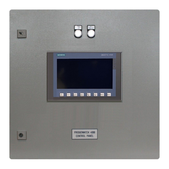
Touch-screen IP rating IP65 (NEMA type 4 at the front) IP66 (NEMA type 4 at the front) Fig 1 Fridgewatch 4000 Controller (Standalone Versions) – Front Panel and HMI Displays Publication 3-71 Section 3 Page 18 of 270 Issue 3.3 : 01/23... -
Page 19: Fig 2 Fridgewatch 4000 Controller (Standalone Standard Version) - Panel Internal Layout
Terminals Trunking For Incoming Cables Gland Plate For 24 V dc Cable Entry Earth Connecting Block Fig 2 Fridgewatch 4000 Controller (Standalone Standard Version) – Panel Internal Layout Section 3 Publication 3-71 Issue 3.3 : 01/23 Page 19 of 270... - Page 20 Fridgewatch 4000 Controller Mk2 Rear of Touch- screen Display Fig 2 (continued) Fridgewatch 4000 Controller (Standalone Standard Version) – Panel Door Mounted Items Publication 3-71 Section 3 Page 20 of 270 Issue 3.3 : 01/23...
-
Page 21: Fig 3 Fridgewatch 4000 Controller (Standalone Standard And Harsh Environment Versions) - Enclosure
Two cam locks. 1 x key supplied with panel. Weight 35 kg (assembled). Rain canopy Fitted to harsh environments FW4000 Mk2 version, outdoor applications. Fig 3 Fridgewatch 4000 Controller (Standalone Standard and Harsh Environment Versions) - Enclosure Section 3 Publication 3-71 Issue 3.3 : 01/23... -
Page 22: Fridgewatch 4000 Controller (Standalone Arrangement) - Mounting
M8 x 25 mm galvanised setscrew M8 Nyloc nut Kit of parts comprising items 1 to 4 available from J & E Hall International part number N13440154 Fig 4 Fridgewatch 4000 Controller (Standalone Arrangement) - Mounting Publication 3-71 Section 3 Page 22 of 270 Issue 3.3 : 01/23... -
Page 23: Fridgewatch 4000 Controller (Standalone Arrangement) - Hmi Interface
Fridgewatch 4000 Controller Mk2 4.1.3. Fridgewatch 4000 Controller (Standalone Arrangement) - HMI Interface The panel door mounted HMI for the standalone arrangement of the FW4000 features the following: • Large Siemens colour touch-screen display; refer to Fig 1; • Key operating parameters displayed on the Home Page; the compressor can be manually started and stopped from this page. -
Page 24: Safety Monitoring
Fridgewatch 4000 Controller Mk2 5.1.1. Safety Monitoring FW4000 monitors the safe operation of the plant and, in the event of a fault condition, displays where the fault lies. FW4000 can be configured to use conventional electro-mechanical cut-out devices for pressure and temperature safety trips, and/or these trip functions can be performed in software using values read from pressure and temperature transmitters. -
Page 25: Limiting
Fridgewatch 4000 Controller Mk2 Set Point DIGIN l201.5 Set Point Defined by Reference Variable Priority S1 Set Point Value SC15 Control Variable First Set Point False S2 Start Value SC16 Start Variable Set Point (S1) used S3 Stop Value SC17 Stop Variable... -
Page 26: Principles Of Control
Fridgewatch 4000 Controller Mk2 Principles of Control The primary requirement of any refrigeration control system is to match the measured variable (temperature or pressure) as closely as possible to the required control value (set point), while at the same time optimising the use of available compressor capacity. -
Page 27: Slide Valve Position Signal
Fridgewatch 4000 Controller Mk2 • HS 3200, HS 5200 and HS 6200 series compressors are fitted with a pair of slide valves yoked together and actuated by a piston. For a full description of slide valve operation refer to the Compressors Manual in Section 2 of the plant instruction manual;... -
Page 28: Fig 5 Proportional And Integral (P + I) Control
Fridgewatch 4000 Controller Mk2 Temperature (°C) or Pressure (bar g) Current Proportional Band Between Maximum and Minimum – See Table Proportional Band at Maximum Proportional Band Steady State Error Control Error at Minimum Set Point Dead-band Measured Value Proportional Band... -
Page 29: Proportional And Integral (P + I) Control
Fridgewatch 4000 Controller Mk2 6.3. Proportional and Integral (P + I) Control Before discussing Proportional and Integral (P + I) control, it is necessary to define some basic terms: • Set point - System Control Settings S1 Set Point Value, the value of pressure, temperature, superheat etc. -
Page 30: Integral Action Time
Fridgewatch 4000 Controller Mk2 A large proportional band achieves stable control, however, the degree of corrective action taken for large errors is relatively small, hence the control response is slow. A large proportional band also permits a large steady state error to exist with no corrective action taking place. -
Page 31: Set Point Temperature/Pressure
Fridgewatch 4000 Controller Mk2 6.3.3. Set Point Temperature/Pressure Refer to Fig 5 Proportional and Integral (P + I) Control. System Control Setting S1 Set Point Value temperature/pressure, depends on the chosen control parameter defined by System Configuration Setting SC15 Control Variable. -
Page 32: Economiser Superheat Set Point
Fridgewatch 4000 Controller Mk2 P + I calculations start 60 seconds after the compressor is requested by the control algorithm. Both Proportional Action and Integral Action are set to 0 when the compressor is not running in ‘auto’ mode. The value for each variable can only be arrived at by subjecting FW4000 to system fluctuations under actual site conditions and modifying each term until the desired response is achieved. -
Page 33: Fig 7 Possible Compressor Start/Stop And Capacity Control Modes
Fridgewatch 4000 Controller Mk2 Operating Mode Selection FW4000 Controller Operating Mode Compressor Started By Compressor Stopped By Capacity Control Starting/ Capacity Stopping Control No control action From the Home Page, START button From the Home Page, CONTROLLED From the Home Page, press the pressed. -
Page 34: Control Philosophy For Compressor Operation After A Transmitter Failure
6.6. Capacity Control by Fridgewatch 4000 There are three basic capacity control modes: • Auto capacity control - by the FW4000 P + I algorithm;... -
Page 35: Manual Capacity Control
Fridgewatch 4000 Controller Mk2 6.6.3. Manual Capacity Control Manual capacity control is the obvious exception to the automatic control schemes already described. In manual capacity control mode, auto capacity control elements are ignored and the operator uses the buttons on the Home Page to generate load and unload pulses. -
Page 36: Other Limiting Conditions
Fridgewatch 4000 Controller Mk2 6.7.5. Other Limiting Conditions In addition to the above, DIGIN l200.1 and DIGIN l200.2 (provided for inputs from an external current limiting device) can also be used to enable limiting from any definable plant condition transmitted to FW4000 as a signal: contacts open or closed. -
Page 37: Oil Management Systems
Fridgewatch 4000 Controller Mk2 6.9. Oil Management Systems FW4000 caters for screw compressors with oil management systems with or without an oil pump: • No oil pump, system suction/discharge pressure differential is high enough to maintain oil flow; • Start-up oil pump, runs to lubricate the gland and bearings before the compressor starts, then stops after a time delay. -
Page 38: Summary Of Differential Pressure Sensing
Fridgewatch 4000 Controller Mk2 6.9.1. Summary of Differential Pressure Sensing • Settings shown shaded and in bold are mandatory, e.g. SC7; • Settings marked as ‘Unused’ are ignored when bold settings are as indicated; • Settings shown in italics may be adjusted during commissioning. -
Page 39: Table 9 Hso 2000 Series Compressors - Oil Pressure Trips By Transmitters
Fridgewatch 4000 Controller Mk2 Standard Solenoid Valve and Pressure Sensing Configuration Setting Arrangement (SC6 Oil Feed Type = 0) Oil Pump/System Type SC5 = → ODP1 Starting Delay → ALTT5 = → ODP2 Starting Delay ALTT4 = Unused Unused Start-up Oil Pump Run Time or →... -
Page 40: Demand Oil Pump
Fridgewatch 4000 Controller Mk2 Standard Solenoid Valve and Pressure Sensing Configuration Setting Arrangement (SC6 Oil Feed Type = 0) Oil Pump/System Type SC5 = → ODP1 Starting Delay → ALTT5 = → ODP2 Starting Delay ALTT4 = Unused Unused Start-up Oil Pump Run Time or →... -
Page 41: Oil Filling Pump
Fridgewatch 4000 Controller Mk2 When the demand pump is not running, the pump is started when net oil injection pressure falls below the SC22 value, i.e. SC22 is a margin above the trip value. When the demand pump is running, it is desirable to stop the pump at another margin above the start value. -
Page 42: Fridgewatch System Controller And Scada
Fridgewatch 4000 Controller Mk2 Fridgewatch System Controller and SCADA The bespoke Fridgewatch System Controller for compressor group control and SCADA for system performance monitoring complement the FW4000 and are particularly suitable for multi-compressor applications. 7.1. Fridgewatch System Controller Refer to Fig 8. -
Page 43: Fig 8 Fridgewatch 4000 Controller Interface With Fridgewatch System Controller
As an alternative, Fridgewatch System Controller and FW4000 electronics can be incorporated in a multi- section panel and the SCADA GUI interface used as the HMI. Fig 8 Fridgewatch 4000 Controller Interface With Fridgewatch System Controller Section 3 Publication 3-71 Issue 3.3 : 01/23... -
Page 44: Fig 9 Fridgewatch 4000 Controller Interface With Scada
Local control of each HallScrew Package unit is via a FW4000 with touch-screen display as shown. As an alternative, FW4000 electronics can be incorporated in a multi-section panel and the SCADA GUI interface used as the HMI. Fig 9 Fridgewatch 4000 Controller Interface With SCADA Publication 3-71 Section 3 Page 44 of 270 Issue 3.3 : 01/23... -
Page 45: Installation
Fridgewatch 4000 Controller Mk2 Installation Installing the FW4000 involves the following steps: • Decide on the controlling parameters, temperature or pressure, from which start, stop and set point values are to be derived; refer to System Configuration Settings SC15, SC16 and SC17;... -
Page 46: Transmitter Wiring
Calibrating inputs is described in 18.1. ANIN Configuration, Calibration. 8.3. Using Fridgewatch 4000 to Drive Relays Start signals from FW4000 to motors, to start the compressor or a pump for example, must only be used to drive a low consumption 24 V dc relay (40 mA maximum);... -
Page 47: Fig 12 Transmitter Installation
Fridgewatch 4000 Controller Mk2 Pressure Transmitter Connection ¼” BSP to 6 mm Compression Fitting 6 mm Suction Pressure Compression Dowty Gauge Fitting Seal Gauge Valve Pressure 6 mm Wire to Transmitter Gauge Line Fridgewatch Framework 6 mm Gauge Line Wire to... -
Page 48: Status Indicators
Fridgewatch 4000 Controller Mk2 Status Indicators There are two status indicators mounted on the panel door above the touch-screen display; refer to Fig 1. CONTROL ON PLC HEALTHY With 24 V dc power supplied to FW4000 and the panel isolator turned to the ‘on’... -
Page 49: Reset Required Indicator, Acknowledge And Reset Buttons
Fridgewatch 4000 Controller Mk2 10.2.3. Reset Required Indicator, Acknowledge and Reset Buttons RESET REQUIRED This indicator appears, greyed-out, in the top right-hand corner of every page. If a trip occurs, RESET REQUIRED is displayed until the trip condition is rectified and the panel reset. -
Page 50: Home Page And Digins
Fridgewatch 4000 Controller Mk2 10.2.6. Home Page and DIGINs HOME PAGE DIGINS The HOME PAGE button is displayed on every page. When FW4000 powers up the Home Page is displayed. The Home Page provides immediate access to the operating status via the key operating parameters displayed on the right-hand side of the page. -
Page 51: Home Page
Fridgewatch 4000 Controller Mk2 Home Page HOME PAGE The Home Page is accessed from the Home Page button on any page. The Home Page, illustrated in Fig 13, provides a thumbnail of the current condition of the system, divided into three main areas: •... -
Page 52: Fig 14 Home Page Example: Compressor 'Available
Fridgewatch 4000 Controller Mk2 Fig 14 Home Page Example: Compressor ‘Available’ Fig 15 Home Page Example: Compressor ‘Tripped’ Publication 3-71 Section 3 Page 52 of 270 Issue 3.3 : 01/23... -
Page 53: Start (Manual Start/Stop Only)
Fridgewatch 4000 Controller Mk2 11.1. Start (Manual Start/Stop Only) START This button is only displayed on the Home Page when ‘manual’ start/stop mode is selected. With the compressor stopped, press the START button to start the compressor if it is available to start. There may be a short delay before the compressor is seen or heard to start. -
Page 54: System Diagnostics
Fridgewatch 4000 Controller Mk2 11.4. System Diagnostics SYSTEM DIAGNOSTICS This button provides a short-cut to the System Diagnostics Page. This page displays the operating state of the system hardware, if a PLC module is faulty or missing, communication errors or other hardware errors. -
Page 55: Menu Page
Fridgewatch 4000 Controller Mk2 Menu Page MENU PAGE The Menu Page displays all available screen pages and is accessed by pressing the Menu Page button on any page. There are three different categories of screen page: Read-only, Operator Settings and Configuration Settings. Each category is colour coded as denoted by the background colour of the ‘soft’... -
Page 56: Read-Only Pages
Fridgewatch 4000 Controller Mk2 12.1. Read-only Pages READ-ONLY PAGES Read-only pages are not password protected. 12.1.1. Digital Inputs DIGITAL INPUTS The Digital Inputs page is accessed from the DIGINs button on the Home Page or from the Menu Page. The digital inputs available for display depends on the application, only those digital inputs configured to FW4000 are displayed. - Page 57 Fridgewatch 4000 Controller Mk2 Fig 18 (continued) Digital Inputs Pages 1 to 3 Fig 18 (continued) Digital Inputs Pages 1 to 3 Section 3 Publication 3-71 Issue 3.3 : 01/23 Page 57 of 270...
-
Page 58: Digital Outputs
Fridgewatch 4000 Controller Mk2 12.1.2. Digital Outputs DIGITAL OUTPUTS The Digital Outputs page is accessed from the Menu Page. The digital outputs available for display depends on the application, only those digital outputs configured to FW4000 are displayed. Fig 18 shows all possible digital outputs connected. - Page 59 Fridgewatch 4000 Controller Mk2 Fig 19 (continued) Digital Outputs Pages 1 to 3 Fig 19 (continued) Digital Outputs Pages 1 to 3 Section 3 Publication 3-71 Issue 3.3 : 01/23 Page 59 of 270...
-
Page 60: Analogue Inputs
Fridgewatch 4000 Controller Mk2 12.1.3. Analogue Inputs ANALOGUE INPUTS The Analogue Inputs page is accessed from the Analogue Inputs button on the Home Page or from the Menu Page. The analogue inputs available for display depends on the application, only those analogue inputs configured to FW4000 are displayed. - Page 61 Fridgewatch 4000 Controller Mk2 Fig 20 (continued) Analogue Inputs Pages 1 to 4 Fig 20 (continued) Analogue Inputs Pages 1 to 4 Section 3 Publication 3-71 Issue 3.3 : 01/23 Page 61 of 270...
-
Page 62: Analogue Outputs
Fridgewatch 4000 Controller Mk2 12.1.4. Analogue Outputs ANALOGUE OUTPUTS The Analogue Outputs page is accessed from the Menu Page. The analogue outputs available for display depends on the application, only those analogue outputs configured to FW4000 are displayed. Fig 18 shows all possible analogue outputs connected. -
Page 63: P + I Diagnostics
Fridgewatch 4000 Controller Mk2 12.1.5. P + I Diagnostics P + I DIAGNOSTICS The P + I Diagnostics page is accessed from the P + I Diag button on the Home Page or from the Menu Page. The diagnostics available for display depends on the application. -
Page 64: Primary/Secondary
Fridgewatch 4000 Controller Mk2 12.1.6. Primary/Secondary PRIMARY/SECONDARY NOT USED The Primary/Secondary compressor pages are accessed from the Menu Page. This page displays system P + I control parameters grouped together for ease of analysis. Fig 22 shows all possible P + I parameters. -
Page 65: Trending And Logging Data
Fridgewatch 4000 Controller Mk2 12.1.7. Trending and Logging Data TRENDING & LOGGING DATA The Trending and Logging Data page is accessed from the Menu Page. The trending and logging data available for display depends on the application. Fig 25 Trending and Logging Data Page 12.1.7.1. -
Page 66: Fig 27 Trending Data - Condenser Inlet And Outlet Temperature
Fridgewatch 4000 Controller Mk2 Fig 27 Trending Data – Condenser Inlet and Outlet Temperature Fig 28 Trending Data – Compressor Discharge, Suction and Oil Temperature Publication 3-71 Section 3 Page 66 of 270 Issue 3.3 : 01/23... -
Page 67: Fig 29 Trending Data - Compressor Discharge, Suction And Oil Injection Pressure
Fridgewatch 4000 Controller Mk2 Fig 29 Trending Data – Compressor Discharge, Suction and Oil Injection Pressure Fig 30 Trending Data – Compressor Capacity Section 3 Publication 3-71 Issue 3.3 : 01/23 Page 67 of 270... -
Page 68: Fig 31 Trending Data - Compressor Motor Current
Fridgewatch 4000 Controller Mk2 Fig 31 Trending Data – Compressor Motor Current Fig 32 Trending Data – Compressor Lub Oil and Net Oil Pressure, Oil Filter Differential Pressure Publication 3-71 Section 3 Page 68 of 270 Issue 3.3 : 01/23... -
Page 69: Fig 33 Trending Data - Compressor Discharge And Suction Superheat
Fridgewatch 4000 Controller Mk2 Fig 33 Trending Data – Compressor Discharge and Suction Superheat 12.1.7.2. Function Keys Function Remarks Toggle: press to start the trending update, press again to stop. Values are Start/stop buffered and are updated as soon as the update begins. -
Page 70: Fig 34 Trending Example 1
Fridgewatch 4000 Controller Mk2 12.1.7.4. Trending Examples The red ruler can be moved left or right by the user to monitor the value at a specific time. In Fig 34 value = ####, the ruler is located before trending begins. - Page 71 Fridgewatch 4000 Controller Mk2 12.1.7.5. Data Logging The data logging function permits the condition of the FW4000 ANIN’s and ANOUT’s to be measured at intervals and the values viewed and, if necessary, archived for future analysis. Data log files are stored in the FW4000 CPU load memory from where they can be viewed and uploaded;...
-
Page 72: Fig 36 Connecting To The Cpu Via Ethernet Cable
Fridgewatch 4000 Controller Mk2 DELETE ‘DATALOG’ FILE DELETE ‘NEWFILE’ FILE Pressing the DELETE ‘DATALOG’ FILE button deletes the Current File, the data log record file being created. Pressing the DELETE ‘NEWFILE’ FILE button deletes the current New File that is being recorded. -
Page 73: Fig 37 Trending And Logging Data - Data Logging
Fridgewatch 4000 Controller Mk2 Fig 37 Trending and Logging Data – Data Logging Section 3 Publication 3-71 Issue 3.3 : 01/23 Page 73 of 270... -
Page 74: Fig 38 Uploading Data Log Files
Fridgewatch 4000 Controller Mk2 1. Type PLC CPU IP Address on the browser: 10.138.100.1 and press ENTER 2. Enter User Name (default fw4000) and Password (default fw4000) 3. Logged in as User fw4000 4. Select Data Logs Press the START... - Page 75 Fridgewatch 4000 Controller Mk2 5. Refresh the webpage on the browser. Click on the DataLog.csv or NewFile.csv file to download and save (see Excel file format in 6.) 6. On NewFile number of records is from 1 to 900 (Column A), UTC...
-
Page 76: Clean Screen
Fridgewatch 4000 Controller Mk2 12.1.8. Clean Screen CLEAN SCREEN The Clean Screen page is accessed from the Menu Page. With the FW4000 in operation, touching the screen will initiate an action making cleaning the screen difficult without powering off and stopping the plant. -
Page 77: Operator Settings Pages
Fridgewatch 4000 Controller Mk2 12.2. Operator Settings Pages Operator Settings Operator Settings pages are password protected; refer to 13. Passwords. 12.2.1. System Control Settings SYSTEM CONTROL SETTINGS The System Control Settings pages are accessed from the Menu Page. System control settings can be viewed at any time, but the value of a setting can only be changed by using the Operator Settings password;... - Page 78 Fridgewatch 4000 Controller Mk2 Fig 40 (continued) System Control Settings Pages 1 to 3 Fig 40 (continued) System Control Settings Pages 1 to 3 Publication 3-71 Section 3 Page 78 of 270 Issue 3.3 : 01/23...
-
Page 79: Economiser Control Settings
Fridgewatch 4000 Controller Mk2 12.2.2. Economiser Control Settings ECONOMISER CONTROL SETTINGS The Economiser Control Settings pages are accessed from the Menu Page. Economiser control settings can be viewed at any time, but the value of a setting can only be changed by using the Operator Settings password;... -
Page 80: Liquid Injection Control Settings
Fridgewatch 4000 Controller Mk2 12.2.3. Liquid Injection Control Settings LIQUID INJECTION CONTROL SETTINGS The Liquid Injection Control Settings page is accessed from the Menu Page. Liquid injection settings can be viewed at any time, but the value of a setting can only be changed by using the Operator Settings password;... -
Page 81: Evaporator And Oil Cooler Control Settings
Fridgewatch 4000 Controller Mk2 12.2.4. Evaporator and Oil Cooler Control Settings EVAPORATOR CONTROL SETTINGS The Evaporator Control Settings pages are accessed from the Menu Page. Evaporator control settings and oil cooler control settings can be viewed at any time, but the value of a setting can only be changed by using the Operator Settings password;... -
Page 82: Condenser Control Settings
Fridgewatch 4000 Controller Mk2 12.2.5. Condenser Control Settings CONDENSER CONTROL SETTINGS The Condenser Control Settings page is accessed from the Menu Page. Condenser control settings can be viewed at any time, but the value of a setting can only be changed by using the Operator Settings password;... -
Page 83: Hot Gas Valve Control Settings
Fridgewatch 4000 Controller Mk2 12.2.6. Hot Gas Valve Control Settings HOT GAS CONTROL SETTINGS The Hot Gas Valve Control Settings page is accessed from the Menu Page. Hot gas valve control settings can be viewed at any time, but the value of a setting can only be changed by using the Operator Settings password;... -
Page 84: Suction Pressure Limiting Control Settings
Fridgewatch 4000 Controller Mk2 12.2.7. Suction Pressure Limiting Control Settings SUCTION PRESSURE LIMITING The Suction Pressure Limiting page is accessed from the Menu Page. Suction pressure limiting control settings can be viewed at any time, but the value of a setting can only be changed by using the Operator Settings password;... -
Page 85: Primary/Secondary Control Settings
Fridgewatch 4000 Controller Mk2 12.2.8. Primary/Secondary Control Settings PRIMARY/SECONDARY SETTINGS The Primary/Secondary Settings page is accessed from the Menu Page. Primary/secondary control settings can be viewed at any time, but the value of a setting can only be changed by using the Operator Settings password;... -
Page 86: Alarm, Limiting And Trip Settings, Delay Times
Fridgewatch 4000 Controller Mk2 12.2.9. Alarm, Limiting and Trip Settings, Delay Times ALARM, LIMIT & TRIP SETTINGS The Alarm, Limit & Trip Settings pages are accessed from the Menu Page. Alarm, Limiting and Trip settings and delay times can be viewed at any time, but the value of a setting can only be changed by using the Operator Settings password;... - Page 87 Fridgewatch 4000 Controller Mk2 Fig 48 (continued) Alarm, Limit & Trip Settings Pages 1 to 11 Fig 48 (continued) Alarm, Limit & Trip Settings Pages 1 to 11 Section 3 Publication 3-71 Issue 3.3 : 01/23 Page 87 of 270...
- Page 88 Fridgewatch 4000 Controller Mk2 Fig 48 (continued) Alarm, Limit & Trip Settings Pages 1 to 11 Fig 48 (continued) Alarm, Limit & Trip Settings Pages 1 to 11 Publication 3-71 Section 3 Page 88 of 270 Issue 3.3 : 01/23...
- Page 89 Fridgewatch 4000 Controller Mk2 Fig 48 (continued) Alarm, Limit & Trip Settings Pages 1 to 11 Fig 48 (continued) Alarm, Limit & Trip Settings Pages 1 to 11 Section 3 Publication 3-71 Issue 3.3 : 01/23 Page 89 of 270...
- Page 90 Fridgewatch 4000 Controller Mk2 Fig 48 (continued) Alarm, Limit & Trip Settings Pages 1 to 11 Fig 48 (continued) Alarm, Limit & Trip Settings Pages 1 to 11 Publication 3-71 Section 3 Page 90 of 270 Issue 3.3 : 01/23...
- Page 91 Fridgewatch 4000 Controller Mk2 Fig 48 (continued) Alarm, Limit & Trip Settings Pages 1 to 11 Fig 48 (continued) Alarm, Limit & Trip Settings Pages 1 to 11 Section 3 Publication 3-71 Issue 3.3 : 01/23 Page 91 of 270...
-
Page 92: Operating Mode
Fridgewatch 4000 Controller Mk2 12.2.10. Operating Mode OPERATING MODE The Operating Mode page is accessed from the Menu Page. This page permits the plant operating mode to be changed. All possible operating modes are illustrated in Fig 7 Possible Compressor Start/Stop and Capacity Control Modes. -
Page 93: Set Time And Date
Fridgewatch 4000 Controller Mk2 12.2.11. Set Time and Date SET TIME AND DATE The Set Time and Date page is accessed from the Menu Page. This page permits the current time and date to be changed. Time and date can only be changed by using the Operator Settings password;... -
Page 94: Configuration Settings
Fridgewatch 4000 Controller Mk2 12.3. Configuration Settings Pages Configuration Settings Configuration Settings pages are password protected; refer to 13. Passwords 12.3.1. ANIN Configuration ANIN CONFIGURATION The ANIN Configuration pages are accessed from the HOME Page. ANIN configuration calibration settings can be viewed at any time, but the value of a setting can only be changed by using the Configuration password;... - Page 95 Fridgewatch 4000 Controller Mk2 Fig 51 (continued) ANIN Configuration Pages 1 to 4 Fig 51 (continued) ANIN Configuration Pages 1 to 4 Section 3 Publication 3-71 Issue 3.3 : 01/23 Page 95 of 270...
- Page 96 Fridgewatch 4000 Controller Mk2 Fig 51 (continued) ANIN Configuration Pages 1 to 4 Publication 3-71 Section 3 Page 96 of 270 Issue 3.3 : 01/23...
-
Page 97: System Configuration Settings
Fridgewatch 4000 Controller Mk2 12.3.2. System Configuration Settings SYSTEM CONFIGURATION The System Configuration settings pages are accessed from the Menu Page. System configuration settings affect the way FW4000 interfaces with the refrigeration plant and must be entered during commissioning, before starting the plant for the first time. - Page 98 Fridgewatch 4000 Controller Mk2 Fig 52 (continued) System Configuration Pages 1 to 6 Fig 52 (continued) System Configuration Pages 1 to 6 Publication 3-71 Section 3 Page 98 of 270 Issue 3.3 : 01/23...
- Page 99 Fridgewatch 4000 Controller Mk2 Fig 52 (continued) System Configuration Pages 1 to 6 Fig 52 (continued) System Configuration Pages 1 to 6 Section 3 Publication 3-71 Issue 3.3 : 01/23 Page 99 of 270...
- Page 100 Fridgewatch 4000 Controller Mk2 Fig 52 (continued) System Configuration Pages 1 to 6 Publication 3-71 Section 3 Page 100 of 270 Issue 3.3 : 01/23...
-
Page 101: Hours Run And Number Of Starts
Fridgewatch 4000 Controller Mk2 12.3.3. Hours Run and Number of Starts HOURS RUN & NO OF STARTS The Hours Run and Number of Starts page is accessed from the Menu Page. The data available for display depends on the application. -
Page 102: Passwords
Fridgewatch 4000 Controller Mk2 Passwords The three different categories of screen page: Read-only, Operator Settings and Configuration Settings are denoted by the background colour of the ‘soft’ keys on the Menu Page and the ‘value’ cell next to the setting description on each settings page; refer to Fig 54. -
Page 103: Entering A Password
Fridgewatch 4000 Controller Mk2 NOTE: Under no circumstances will J & E Hall International accept responsibility for damage to plant or injury to personnel caused by unauthorised password use. 13.2. Entering a Password To change the value of a setting, tap the ‘value’ cell next to the setting description. -
Page 104: Commissioning
Fridgewatch 4000 Controller Mk2 Commissioning These commissioning instructions assume the operator has read and fully understood how the user interface functions; refer to 10. User Interface. Leave commissioning the FW4000 until after the plant has been installed, all refrigerant, condenser cooling water, evaporator cooled medium and electrical connections have been made, and everything is otherwise ready for starting the plant for the first time. -
Page 105: Authority To Use Passwords
Fridgewatch 4000 Controller Mk2 • Define the following Operator Settings depending on the application and input them as described in 14.4: Economiser Control Settings EC1/EC14. Liquid Injection Control Settings LI1/LI9. Evaporator Control Settings E1/E12. Condenser Control Settings C1/C9. Hot Gas Control Settings HG1/HG8. -
Page 106: Changing System Configuration Settings After Commissioning
Fridgewatch 4000 Controller Mk2 14.3.1. Changing System Configuration Settings after Commissioning After initially inputting these values during commissioning, to change a System Configuration Settings, the operating mode must be changed before and after this operation. CAUTION System Configuration Settings SC1/SC45 are fundamental to the way the FW4000 interfaces with the rest of the refrigeration plant. -
Page 107: Fig 56 Viewing Or Changing System Configuration Settings
Fridgewatch 4000 Controller Mk2 To view System Configuration Settings, from the Menu Page press the SYSTEM CONFIGURATION button. To change a setting, touch the setting to be changed, in this example, Refrigerant. Enter the Commissioning password, refer to 13. Passwords. A Touch Input Panel screen appears with all possible values for this setting displayed. -
Page 108: Fig 57 Viewing Or Changing Control Settings
Fridgewatch 4000 Controller Mk2 To view control settings, from the Menu Page press the desired control settings button, ALARM, LIMIT & TRIP SETTINGS in this example. To change a setting, touch the setting to be changed, in this example, Suction Pressure High Alarm. Enter the Technician password or higher access level, refer to 13. -
Page 109: Fig 58 Viewing Or Changing Operator Settings
Fridgewatch 4000 Controller Mk2 From the Menu Page, press the OPERATING MODE button to display the Operating Mode Selection page. Touch the current operating mode to display the Touch Input Panel (if necessary, enter Supervisor password or higher access level, refer to 13. Passwords). - Page 110 Fridgewatch 4000 Controller Mk2 Touch the new operating mode or use the scroll buttons to select it (in this example MANUAL start/stop – AUTO capacity control). Press the button to implement the new mode. The Operating Mode Selection page appears with the new operating mode displayed.
-
Page 111: Display Messages
Fridgewatch 4000 Controller Mk2 Display Messages Certain operating conditions, including alarm conditions which provide advisory warning and fault conditions which trip and stop the compressor, are detected and displayed by FW4000. There are three basic types of display message: • Information Only - provide operational or status information to the operator, this includes limiting conditions;... -
Page 112: Alarm, Trip And Information Only Messages
Fridgewatch 4000 Controller Mk2 15.4. Alarm, Trip and Information Only Messages This part of the manual provides a full description of alarm, trip and information only messages which may appear in the Limiting, Current Alarms or Alarm History pages; refer to Fig 60. A quick-reference to all messages may be found in Appendix 5 HMI Display Message. -
Page 113: Discharge Pressure High: Alarm, Limiting And Trip
Fridgewatch 4000 Controller Mk2 15.4.4. Discharge Pressure High: Alarm, Limiting and Trip Discharge Pressure Alarm, Limiting and Trip Using Transmitter Wired to ANIN 0 Discharge Pressure Message on Display Cause Remarks ‘Discharge Pressure Load Discharge pressure has risen above the ALT9 load inhibit value. -
Page 114: Oil Differential Pressure At Start-Up (Odp2) Low: Trip
Fridgewatch 4000 Controller Mk2 15.4.7. Oil Differential Pressure at Start-up (ODP2) Low: Trip Oil Differential Pressure at Start-up (ODP2) Using Transmitters Differential Pressure Message on Display Cause Remarks Adequate oil differential pressure (ALT13 trip value) was not SC7 = 2 or 3: transmitters established within ALTT4 seconds of the oil pump starting. -
Page 115: Oil Filter Differential Pressure High: Alarm And Trip
Fridgewatch 4000 Controller Mk2 15.4.9. Oil Filter Differential Pressure High: Alarm and Trip Oil Filter Differential Pressure High Alarm and Trip Using Transmitters Differential Pressure Message on Display Cause Remarks ‘Oil Filter Diff Press High Oil filter differential pressure has risen above the ALT16 alarm High - Alarm Alarm, manual reset. -
Page 116: Oil Separator/Reservoir Level Low: Trip
Fridgewatch 4000 Controller Mk2 15.4.12. Oil Separator/Reservoir Level Low: Trip Opto sensor located in the oil separator at a point corresponding to a low oil level. Opto sensor relay 2K2 wired to DIGIN I100.4 Implementation terminals X1.50/X1.52. Message on Display ‘Oil Level Trip’... -
Page 117: Condenser Cooling Medium Inlet Temperature: Alarm
Fridgewatch 4000 Controller Mk2 15.4.16. Condenser Cooling Medium Inlet Temperature: Alarm Condenser Cooling Medium Inlet Temperature Alarm Using Transmitter Wired to ANIN 14 Inlet Temperature Message on Display Cause Remarks ‘Cond Water Inlet Temp Condenser cooling medium inlet temperature has risen above the High - Alarm High Alarm’... -
Page 118: Evaporator Cooled Medium Outlet Temperature: Alarm, Limiting And Trip
Fridgewatch 4000 Controller Mk2 15.4.20. Evaporator Cooled Medium Outlet Temperature: Alarm, Limiting and Trip Evaporator Cooled Medium Outlet Temperature Alarm, Limiting and Trip Using Transmitter Wired to ANIN 13 Outlet Temperature Message on Display Cause Remarks ‘Evap Outlet Temp Load... -
Page 119: Evaporator Liquid Level: Alarm And Trip
Fridgewatch 4000 Controller Mk2 15.4.22. Evaporator Liquid Level: Alarm and Trip Evaporator Liquid Level Alarm and Trip Using Transmitter Wired to ANIN 20 Liquid Level Message on Display Cause Remarks ‘Evaporator Level High Evaporator liquid level has risen above the ALT51 alarm value for High - Alarm Alarm, manual reset. -
Page 120: Compressor Motor Or Starter Failure
Fridgewatch 4000 Controller Mk2 15.4.25. Compressor Motor or Starter Failure Implementation Compressor motor running signal wired to DIGIN I200.3 terminals Dla.3/+24 V X1.1/X1.16. DIGIN Condition Message on Display ‘Comp Failed to Start’ Compressor Motor When FW4000 sends a start signal to the compressor motor, a ‘running’ signal must be returned... -
Page 121: Oil Pump Motor Or Starter Failure
Fridgewatch 4000 Controller Mk2 15.4.26. Oil Pump Motor or Starter Failure Implemented for applications where an oil pump is fitted (SC5 = 1, 2 or 3). Implementation Oil pump motor running signal wired to DIGIN I200.4 terminals Dla.4/+24 V X1.1/X1.17. -
Page 122: Condenser Pump/Fan Motor Or Starter Failure
Fridgewatch 4000 Controller Mk2 15.4.27. Condenser Pump/Fan Motor or Starter Failure Condenser pump/fan motor running signal wired to DIGIN I200.6 terminals Dla.6/+24 V Implementation X1.1/X1.19. DIGIN Condition Message on Display ‘Cond Failed to Start’ Condenser Pump/Fan Motor Failed to Start When FW4000 sends a start signal to the condenser pump/fan motor, a ‘running’... -
Page 123: Evaporator Cooled Medium Pump Motor Or Starter Failure
Fridgewatch 4000 Controller Mk2 15.4.28. Evaporator Cooled Medium Pump Motor or Starter Failure Evaporator cooled medium pump motor running signal wired to DIGIN I200.5 terminals Implementation Dla.5/+24 V X1.1/X1.18. DIGIN Condition Message on Display ‘Evap Pump Failed to Start’ Evaporator Pump Motor Failed to Start When FW4000 sends a start signal to the evaporator pump motor, a ‘running’... -
Page 124: Starting Or Loading Inhibited
Fridgewatch 4000 Controller Mk2 15.4.31. Starting or Loading Inhibited Implementation Inhibit device contacts wired to DIGIN I200.7 terminals Dla.7/+24 V X1.1/X1.20. DIGIN Condition Inhibit Starting ‘Start Inhibited by DIGIN I200.7’ Message on Display Loading (compressor running) ‘Loading Inhibited by DIGIN I200.7’... -
Page 125: External Controller Fault: Evaporator, Economiser, Oil Rectifier Or Liquid Injection
Fridgewatch 4000 Controller Mk2 15.4.33. External Controller Fault: Evaporator, Economiser, Oil Rectifier or Liquid Injection Implementation Evaporator controller fault signal wired to DIGIN I301.0 terminals Dlb.0/+24 V X1.1/X1.33. DIGIN Condition Tripped (DIGIN ‘on’) Message on Display ‘Evap Controller Fault’ Evaporator Controller Fault Cause Evaporator controller has supplied a fault signal to FW4000. -
Page 126: Refrigerant Leak Detector
Fridgewatch 4000 Controller Mk2 15.4.1. Refrigerant Leak Detector Implementation Refrigerant leak detector alarm signal wired to DIGIN I301.6 terminals Dlb.6/+24 V X1.1/X1.39. DIGIN Condition Alarm (DIGIN ‘off’) Message on Display ‘Refrigerant Leak Detector Alarm’ Refrigerant Leak Detector Alarm Cause Refrigerant leak detector has supplied an alarm signal to FW4000. -
Page 127: External Reset And Alarms, Clearing Alarms And Trips
Fridgewatch 4000 Controller Mk2 External Reset and Alarms, Clearing Alarms and Trips 16.1. External Alarm/Trip Acknowledge/Reset It is possible to acknowledge and reset alarms and trips via a signal from an external button, switch or other device as an alternative to using the ‘soft’... -
Page 128: Alarm Condition
Fridgewatch 4000 Controller Mk2 16.4.2. Alarm Condition Compressor status is RUNNING before and after the alarm occurs. When an alarm occurs, New Alarm is displayed on the panel and ‘flashes’ to draw the operator’s attention. If CURRENT ALARMS (F3) is pressed the Current Alarms page appears on the display with the new alarm as the last entry;... -
Page 129: Fig 59 Identifying And Clearing Alarms And Trips
Fridgewatch 4000 Controller Mk2 (1) Normal Healthy Condition If external audible and visual alarm devices are connected to DIGOUTs Q201.5 and Q201.6 refer to Table 47. (2) Alarm Condition If external audible and visual alarm devices are connected to DIGOUTs Q201.5 and Q201.6 refer to Table 47. - Page 130 Fridgewatch 4000 Controller Mk2 (3) Acknowledge Alarm If external audible and visual alarm devices are connected to DIGOUTs Q201.5 and Q201.6 refer to Table 47. (4) Trip Event If external audible and visual alarm devices are connected to DIGOUTs Q201.5 and Q201.6 refer to Table 47.
-
Page 131: Fig 60 Limiting, Alarm And Alarm History Screens
Fridgewatch 4000 Controller Mk2 Limiting conditions are displayed on the Limiting page. Current alarms and trips are displayed on the Current Alarms page. Once the alarm or trip has been acknowledged, rectified and reset if required it is archived on the Alarm History page. -
Page 132: Operator Settings
Fridgewatch 4000 Controller Mk2 Operator Settings Operator Settings and Configuration Settings, configurable by the password holder or J & E Hall commissioning engineer, enable FW4000 to provide suitable control according to the configuration of the refrigeration system. Settings are password protected and backed up in non-volatile memory. -
Page 133: Set Point, Start And Stop Values
Fridgewatch 4000 Controller Mk2 17.1.1. Set Point, Start and Stop Values The options for set point control are described in 5.1.2 and illustrated in Table 4. Set Point, start and stop values, second set point and set point override are described in 5.1.3 and illustrated in Table 5. -
Page 134: Compressor Unload Limit
Fridgewatch 4000 Controller Mk2 Integral action time (units: second) This is the time, in seconds, required for the integral action to duplicate the proportional action. The integral term in the P + I algorithm is used to remove the steady state error which occurs with large and therefore stable proportional bands, once compressor capacity is as close as possible to that required. -
Page 135: Intermediate Load Outputs
Fridgewatch 4000 Controller Mk2 17.1.6. Intermediate Load Outputs Intermediate load output 1: level (units: % of full load) Intermediate load output 1: differential (units: %) This output is on DIGOUT Q200.6; refer to Fig 81. S13 determines the slide valve position (SVP)/motor speed at which this output switches. On increasing load the output switches when ANIN 7 slide valve position (SVP) %/motor speed %, rises above the value of S13. -
Page 136: Fig 61 Example Of Using Intermediate Load Output 1
Fridgewatch 4000 Controller Mk2 P4 % Load 50 % Loading Unloading 40 % Intermediate load output 1: switching position on increasing load 30 % S13 = 30 % Intermediate load output 1: switching position on decreasing load 20 % (S13 - S14) = (30 - 10)% = 20 %... -
Page 137: Variable Volume Ratio (Vv ) Configuration For Hallscrew 5200 And 6200 Series Compressors
Fridgewatch 4000 Controller Mk2 17.1.1. Variable Volume Ratio (VV ) Configuration For HallScrew 5200 and 6200 Series Compressors Variable Volume Ratio (VV ) is an option for HallScrew 5200 and 6200 Series Compressors, permitting compressor performance to be optimised for inverter drive applications. -
Page 138: Economiser Control Settings
Fridgewatch 4000 Controller Mk2 17.2. Economiser Control Settings ECONOMISER CONTROL SETTINGS The Economiser Control Settings pages are accessed from the Menu Page and illustrated in Fig 41. Economiser Control Settings can be viewed at any time, but can only be changed by using the Operator Settings password;... -
Page 139: Fig 62 Cycle Time
Fridgewatch 4000 Controller Mk2 Integral action dead-band (units: K) EC5 is the size of the dead-band either side (±) of EC1 Superheat Set Point Value; refer to 6. Principles of Control. With the measured economiser superheat inside the dead-band, no integral control action takes place, i.e. -
Page 140: Economiser Control Enable And Disable
Fridgewatch 4000 Controller Mk2 Maximum operating pressure (units: %) Maximum Operating Pressure (MOP) refers to the maximum value that suction pressure is permitted to rise to before the valve begins to close and restrict refrigerant flow, thus preventing evaporating pressure rising above the MOP setting. -
Page 141: Liquid Injection Control Settings
Fridgewatch 4000 Controller Mk2 17.3. Liquid Injection Control Settings LIQUID INJECTION CONTROL SETTINGS The Liquid Injection Control Settings page is accessed from the Menu Page and illustrated in Fig 42. Liquid Injection Control Settings can be viewed at any time, but can only be changed by using the Operator Settings password;... - Page 142 Fridgewatch 4000 Controller Mk2 Integral action dead-band (units: °C) LI6 is the size of the dead-band either side (±) of LI1 Discharge Temperature Set Point Value; refer to 6. Principles of Control. With the measured discharge temperature inside the dead-band, no integral control action takes place, i.e.
-
Page 143: Evaporator And Oil Cooler Control Settings
Fridgewatch 4000 Controller Mk2 17.4. Evaporator and Oil Cooler Control Settings EVAPORATOR CONTROL SETTINGS The Evaporator and Oil Cooler Control Settings pages are accessed from the Menu Page and illustrated in Fig 43. Evaporator and Oil Cooler Control Settings can be viewed at any time, but can only be changed by using the Operator Settings password;... - Page 144 Fridgewatch 4000 Controller Mk2 Integral action time (units: second) This is the time, in seconds, required for the integral action to duplicate the proportional action. The integral term in the P + I algorithm is used to remove the steady state error which occurs with large and therefore stable proportional bands, once evaporator expansion valve capacity is as close as possible to that required.
-
Page 145: Oil Cooler Control Settings
Fridgewatch 4000 Controller Mk2 Sample time (for modulating valves only) (units: second) E8 is only applicable to modulating valves, for example, Danfoss ICM + ICAD. The control response is re-assessed at this time interval. Beware of entering too small a value in the desire to improve response, as this could lead to instability in the overall control of the evaporator expansion valve. -
Page 146: Condenser Control Settings
Fridgewatch 4000 Controller Mk2 17.5. Condenser Control Settings CONDENSER CONTROL SETTINGS The Condenser Control Settings page is accessed from the Menu Page and illustrated in Fig 44. Condenser Control Settings can be viewed at any time, but can only be changed by using the Operator Settings password;... - Page 147 Fridgewatch 4000 Controller Mk2 Proportional band (units: bar g) This is the deviation from the set point resulting in the maximum possible change to condensing pressure. Using too small a proportional band setting will cause instability as small changes in the measured value give rise to large changes in condensing pressure.
-
Page 148: Hot Gas Bypass Valve Control Settings
Fridgewatch 4000 Controller Mk2 17.6. Hot Gas Bypass Valve Control Settings HOT GAS CONTROL SETTINGS The Hot Gas Valve Control Settings page is accessed from the Menu Page and illustrated in Fig 45. Hot Gas Valve Settings can be viewed at any time, but can only be changed by using the Operator Settings password;... - Page 149 Fridgewatch 4000 Controller Mk2 Integral action time (units: second) This is the time, in seconds, required for the integral action to duplicate the proportional action. The integral term in the P + I algorithm is used to remove the steady state error which occurs with large and therefore stable proportional bands, once hot gas bypass valve capacity is as close as possible to that required.
-
Page 150: Primary/Secondary Control Settings
Fridgewatch 4000 Controller Mk2 17.7. Primary/Secondary Control Settings PRIMARY/SECONDARY CONTROL SETTINGS The Primary/Secondary Control Settings page is accessed from the Menu Page and illustrated in Fig 47. Primary/Secondary Settings can be viewed at any time, but can only be changed when logged on at Technician Access Level or higher; refer to 13. -
Page 151: Suction Pressure Limiting Control Valve Settings
Fridgewatch 4000 Controller Mk2 17.8. Suction Pressure Limiting Control Valve Settings The Suction Pressure Limiting Control Valve Settings page is accessed from the Menu Page and illustrated in Fig 46. Suction Pressure Limiting Control Valve Settings can be viewed at any time, but can only be changed by using the Operator Settings password;... - Page 152 Fridgewatch 4000 Controller Mk2 SPL4 Integral action dead-band (units: pressure in bar g) SPL4 is the size of the dead-band either side (±) of SPL1 Set Point Value; refer to 6. Principles of Control. With the measured suction pressure inside the dead-band, no integral control action takes place, i.e.
-
Page 153: Alarm, Limiting And Trip Settings, Delay Times
Fridgewatch 4000 Controller Mk2 17.9. Alarm, Limiting and Trip Settings, Delay Times ALARM, LIMIT & TRIP SETTINGS The Alarm, Limiting and Trip Settings pages are accessed from the Menu Page and illustrated in Fig 48. Alarm, Limiting and Trip Settings, Delay Times can be viewed at any time, but can only be changed by using the Operator Settings password;... -
Page 154: Suction Pressure Low
Fridgewatch 4000 Controller Mk2 Discharge Pressure ALT12 Discharge pressure high trip ALT11 Discharge pressure high alarm ALT10 Discharge pressure high: force unload ALT9 Discharge pressure high: load inhibit Time → Time delay ALTT3 initiated ALTT3 times out. FW4000 displays ‘Discharge Pressure High Alarm’... -
Page 155: Suction Pressure High
Fridgewatch 4000 Controller Mk2 Suction Pressure ALT2 Suction pressure low: load inhibit ALT3 Suction pressure low: force unload ALT7 Suction pressure low alarm ALT8 Suction pressure low trip Time → Time delay ALTT2 initiated ALTT2 times out. FW4000 displays ‘Suction Pressure Low Alarm’... -
Page 156: Oil Differential Pressure Low During Running
Fridgewatch 4000 Controller Mk2 Systems with a start-up oil pump (SC5 = 1): ALTT4 is the time in seconds allowed for the start-up oil pump to establish a discharge/oil pump pressure differential in excess of the ALT13 trip value. Systems with separate solenoid valves in the oil feed and oil injection... -
Page 157: Oil Filter Differential Pressure High
Fridgewatch 4000 Controller Mk2 Oil Diff Press ALT14 Oil diff pressure during running (ODP1) low alarm ALT15 Oil diff pressure during running (ODP1) low trip Time → Oil pump starts. Time delay ALTT5 initiated to allow differential pressure to build and exceed the ALT15 trip setting. -
Page 158: Lube Oil Temperature High
Fridgewatch 4000 Controller Mk2 17.9.9. Lube Oil Temperature High Transmitter wired to ANIN 23, used to sense lube oil temperature. ALT20 Lube oil temperature high alarm (units °C) ALT21 Lube oil temperature high trip (units °C) ALTT9 Lube oil temperature high alarm delay time (units second) If lube oil temperature rises to the ALT20 alarm value, time delay ALTT9 is initiated. -
Page 159: Condenser Cooling Medium Differential Pressure Low
Fridgewatch 4000 Controller Mk2 17.9.14. Condenser Cooling Medium Differential Pressure Low Transmitter wired to ANIN 22, used to sense condenser cooling medium inlet/outlet differential pressure. ALT43 Condenser differential pressure low alarm (units bar) ALT44 Condenser differential pressure low trip (units bar) -
Page 160: Evaporator Liquid Level
Fridgewatch 4000 Controller Mk2 Cond Diff Press ALT43 Condenser differential pressure low alarm ALT44 Condenser differential pressure low trip Time → Condenser pump starts. Time delay ALTT33 initiated to allow differential pressure to build and exceed the ALT44 trip setting. -
Page 161: Evaporator Cooled Medium Outlet Temperature Low
Fridgewatch 4000 Controller Mk2 Evaporator Liquid Level Timer Condition Remarks ALTT35 Evaporator level high trip delay time times out. FW4000 stops the compressor and displays ‘Evaporator Level High Trip’. Evaporator liquid level rises to trip level. Time delay ALTT35 initiated. -
Page 162: Evaporator Cooled Medium Outlet Temperature High
Fridgewatch 4000 Controller Mk2 Evap Out Temp ALT24 Evaporator outlet temperature low: load inhibit ALT25 Evaporator outlet temperature low: force unload ALT26 Evaporator outlet temperature low alarm ALT27 Evaporator outlet temperature low trip Time → Time delay ALTT11 initiated ALTT11 times out. FW4000 displays ‘Evap Outlet Temp Low Alarm’... -
Page 163: Evaporator Cooled Medium Differential Pressure Low
Fridgewatch 4000 Controller Mk2 If evaporator cooled medium differential pressure rises to the ALT32 trip value, FW4000 stops the compressor and displays ‘Evap Diff Press High Trip’. Evaporator differential pressure nuisance trip delay time ALTT14 is designed to prevent a sudden temporary increase in cooled medium differential pressure from opening safety trip contacts and stopping the plant. -
Page 164: Suction Superheat Low
Fridgewatch 4000 Controller Mk2 Evap Diff Press ALT33 Evaporator differential pressure low alarm ALT34 Evaporator differential pressure low trip Time → Evaporator pump starts. Time delay ALTT32 initiated to allow differential pressure to build and exceed the ALT34 trip setting. -
Page 165: Discharge Superheat Low
Fridgewatch 4000 Controller Mk2 17.9.10. Discharge Superheat Low Requires discharge pressure transmitter ANIN 0 and discharge temperature transmitter ANIN 8, SC2 Refrigerant used to define system refrigerant. ALT38 Discharge superheat low alarm (units: K) ALTT20 Discharge superheat low alarm delay time (units: second) If discharge superheat falls to the ALT38 alarm value, time delay ALTT20 is initiated. -
Page 166: Configuration Settings
Fridgewatch 4000 Controller Mk2 Configuration Settings Configuration Settings and Operator settings, configurable by the password holder or J & E Hall commissioning engineer, enable FW4000 to provide suitable control according to the configuration of the refrigeration system. Settings are password protected and backed up in non-volatile memory. -
Page 167: Pressure Transmitter Calibration
Fridgewatch 4000 Controller Mk2 Example 1 Discharge pressure transmitter. Input: 0.0 to 25.0 bar g, output 4 to 20 mA. Scaled Reading Reading ANIN Discharge Pressure (ANIN 0) Data Value @ 4 mA @ 20 mA Selected Transmitter not connected 00000 -6.25... -
Page 168: Temperature Transmitter Calibration
Fridgewatch 4000 Controller Mk2 Reduce the pressure to atmospheric and check the analogue input displays 0.0. If calibrating the reading at maximum pressure has caused the zero point to drift repeat step (d). If, after scaling the readings, the required accuracy cannot be achieved then the transmitter or interconnecting wiring is probably defective. -
Page 169: Motor Current Transmitter Calibration
Fridgewatch 4000 Controller Mk2 18.1.4. Motor Current Transmitter Calibration From the Menu Page, press the button to display ANIN 05 Motor Current/Power. Provided the ANIN is enabled (ANIN used = 1), the current value of ANIN 05 appears in the display. -
Page 170: System Configuration
Fridgewatch 4000 Controller Mk2 18.2. System Configuration SYSTEM CONFIGURATION The System Configuration settings pages are accessed from the Menu Page and illustrated in Fig 52. System Configuration settings are set by the commissioning engineer and should not need modification unless physical changes are made to the plant. -
Page 171: Compressor Drive
Fridgewatch 4000 Controller Mk2 18.2.3. Compressor Drive Fixed or variable speed drive The value of this setting depends on the type of compressor drive. SC3 = 0: Fixed speed. SC3 = 1: Variable speed drive via an inverter. If SC3 = 0, fixed speed drive, set SC41 Analogue Output 5 Definition to 0, i.e. -
Page 172: Oil Differential Pressure During Running
Fridgewatch 4000 Controller Mk2 SC7 Value ODP2 Differential Remarks ODP2 is not used for the type of oil management system in question. Not used. SC5 = 0, 2 or 3. ODP switch used. Oil injection pressure connected to switch HP, discharge Use for applications using a start-up oil pump. -
Page 173: Oil Filter Differential Pressure
Fridgewatch 4000 Controller Mk2 18.2.8. Oil Filter Differential Pressure Oil filter differential sensing defined If oil pressure before and after the oil filter is available, by setting SC9 to non-zero FW4000 will calculate the oil pressure drop across the filter and display Oil Filter Delta P on the Home Page. -
Page 174: Compressor Capacity Control Valve Type
Fridgewatch 4000 Controller Mk2 18.2.9. Compressor Capacity Control Valve Type SC10 Capacity control valve type The value of SC10 to use for a particular application depends on the HallScrew compressor series FW4000 is applied to and the capacity control solenoid valve type. -
Page 175: Compressor Slide Valve Position/Motor Speed Correction
Fridgewatch 4000 Controller Mk2 18.2.10. Compressor Slide Valve Position/Motor Speed Correction The position of the internal slide valves or the speed of the drive motor can be used to modulate compressor pumping capacity. Settings SC3 Fixed or Variable Speed Drive and SC41 Analogue Output 5 Definition are used to define the type of drive and the method of capacity modulation. -
Page 176: Fig 72 Slide Valve Position (Svp)/Motor Speed: Error Tolerance - Values For Sc11
Fridgewatch 4000 Controller Mk2 If motor speed fails to reach the required value before SC12 times out, FW4000 displays the alarm ‘Slide Valve Position (Motor Speed) Error’. This is an alarm only, the compressor is not stopped. If motor speed required is ≥ 100 % and the compressor is not undergoing limiting, one load pulse is sent once every sample time to ensure compressor motor speed is held at 100 %. -
Page 177: Slide Valve Position/Motor Speed Value For Minimum Load
Fridgewatch 4000 Controller Mk2 Example 3: In this example the slide valves move by 7 % during one load/unload pulse. The slide valve error (SC11 value) is set to 2 %. If the required slide valve position is 72 % and the actual slide valve position is 69 %, the slide valves will load to 76 % (69 % + 7 %). -
Page 178: Run Enable Signal
Fridgewatch 4000 Controller Mk2 SC46 Second set point enable/disable SC46 = 0: off, disabled. SC46 = 1: on, enabled. For applications using a second set point, with SC46 = 1 the second set point is active when DIGIN l201.5 is ‘true’. The second set point takes priority over set point S1 and ANIN 24 Remote Set Point. -
Page 179: Compressor Start Time
Fridgewatch 4000 Controller Mk2 18.2.15. Compressor Start Time SC19 Compressor start time (units: second) This is the time in seconds for the compressor motor to start and provide a ‘running’ signal to FW4000. If a ‘compressor running’ signal is not provided before SC19 seconds expire, FW4000 terminates the start sequence and displays a trip: ‘Comp Failed to Start. -
Page 180: Evaporator Pump Selection, Start And Run Times
Fridgewatch 4000 Controller Mk2 18.2.18. Evaporator Pump Selection, Start and Run Times SC24 Evaporator pump start time (units: second) SC24 is the time in seconds allowed for the evaporator cooled medium pump to start and provide a ‘running’ signal to FW4000. If the ‘evaporator pump running’... -
Page 181: Oil Rectifier Enable
Fridgewatch 4000 Controller Mk2 Pump-down is terminated when the measured suction pressure value (ANIN 1) falls to the required value. Setting SC31 Pump-down Maximum Duration is used to terminate pump-down if, for any reason, suction pressure fails to fall to the termination value. -
Page 182: Evaporator Superheat Or Liquid Level Control Enable
Fridgewatch 4000 Controller Mk2 18.2.23. Evaporator Superheat or Liquid Level Control Enable SC35 Evaporator superheat or liquid level control required If evaporator control is required by FW4000, set SC35 = 1 (on) and enter values for SC36, SC37 and E1/E12. -
Page 183: Compressor Slide Valve Position/Motor Speed Definition
Fridgewatch 4000 Controller Mk2 18.2.26. Compressor Slide Valve Position/Motor Speed Definition SC41 Analogue Output 5 Definition SC41 defines the method of modulating compressor pumping capacity. SC41 = 0: compressor slide valve position (SVP). SC41 = 1: compressor motor speed. If SC41 = 0, compressor slide valve position (SVP), set SC3 Fixed or Variable Speed Drive to 0, i.e. -
Page 184: Hot Gas Bypass Valve Or Suction Pressure Limiting Control Enable
Fridgewatch 4000 Controller Mk2 18.2.29. Hot Gas Bypass Valve or Suction Pressure Limiting Control Enable SC47 Hot gas bypass valve required If hot gas bypass valve control is required by FW4000, set SC47 = 1 and enter values for HG1/HG8. If suction pressure limiting control is required by FW4000, set SC47 = 2 and enter values for SPL1/SPL8 SC47 = 0: off. -
Page 185: Primary/Secondary
Fridgewatch 4000 Controller Mk2 18.2.31. Primary/Secondary SC50 Primary/Secondary Required If primary/secondary compressor control is required by FW4000, set SC49 = 1 (on) and enter values for PS1/PS5. SC50 = 0: off. SC50 = 1: primary (this FW4000 is designated as primary). -
Page 186: Fig 73 Example Of Fw4000 Display Page In Metric And Imperial Units
Fridgewatch 4000 Controller Mk2 Fig 73 Example of FW4000 Display Page in Metric and Imperial Units Input Range Type Output Metric Imperial 0.0 to 10.0 bar g 0.0 to 145.04 psi Pressure Transmitter 0.0 to 25.0 bar g 0.0 to 362.6 psi 0.0 to 200.0 bar... -
Page 187: Maintenance
Fridgewatch 4000 Controller Mk2 Maintenance Under normal operating conditions with the FW4000 operating correctly, minimum servicing is required or recommended. The following general checks are recommended once a year. • Check measured point values against pressure gauges, thermometers and current meter readings;... -
Page 188: Fig 74 Fw4000 Stand-Alone Version Internal Equipment Layout And Terminal Arrangement
Fridgewatch 4000 Controller Mk2 7, 8 AND 9 ANALOGUE 2 AND 3 DIGITAL 4, 5 AND 6 ANALOGUE I/O MODULES I/O MODULES INPUT MODULES RS485 COMMS BOARD ETHERNET ANTI- HEATER MODULE CONDENSATION THERMOSTAT (X5) RS485 TERMINALS ISOLATOR FUSES FS1 (refer to Fig 75... -
Page 189: Table 58 Fuses And Relays, Electronic Modules And Hmi
Fridgewatch 4000 Controller Mk2 Part Number or Location Protects Type Number CPU and DIGINS Opto sensors and solenoids ANINS 6 x 20 HRC Ethernet switch Panel anti-condensation heater Discharge pressure high trip switch Oil separator level opto sensor Oil drain opto sensor... -
Page 190: Table 59 Residual Risk Register
The Discharge Pressure Transmitter shall not be relied upon as the sole means of over- pressure protection. NOTE: In the text ‘the product’ refers to the Fridgewatch 4000 Mk2 Controller. Table 59 Residual Risk Register Publication 3-71 Section 3 Page 190 of 270 Issue 3.3 : 01/23... -
Page 191: Fig 75 Panel Isolator Iq1 For Incoming 24 V Dc 10 Amp Supply
Fridgewatch 4000 Controller Mk2 Appendix 2 Wiring Connections The wiring diagrams in this manual refer to stand-alone FW4000 Controllers. If FW4000 electronics are incorporated in a multi-section panel, terminal numbers may be different; refer to the wiring diagrams specific to the application. -
Page 192: Fig 77 Slot 1 Cpu On Board Digins, Addresses I100.0 To I101.5, Anin 24 And Anout 6
Fridgewatch 4000 Controller Mk2 SPARE ANIN CONTINUED IN Fig 78 REMOTE SET REMOTE SET POINT POINT SPARE ANOUT HOT GAS HOT GAS /SUCTION VALVE/SUCTION PRESSURE PRESSURE LIMITING VALVE LIMITING VALVE POSITION POSITION 4 to 20 mA ACKNOWLEDGE/ RESET CONDENSER STARTER... - Page 193 Fridgewatch 4000 Controller Mk2 FW4000 DIGIN Description Remarks Address Discharge pressure high relay 2K1 contacts open on fault condition. FW4000 displays a trip, ‘HP Switch Trip’. I100.0 Discharge high pressure trip switch Relay contacts shown in ‘healthy’ condition. A discharge high pressure trip switch is used for all applications.
-
Page 194: Fig 78 Slot 2 Cpu On Board Digins, Addresses I200.0 To I201.7
Fridgewatch 4000 Controller Mk2 CONTINUED IN Fig 79 RESERVED (DO NOT USE) OIL FILL BUTTON SECOND SET POINT EVAPORATOR TEMPERATURE MOTOR HIGH TEMPERATURE TRIP SWITCH OIL HIGH TEMPERATURE TRIP SWITCH DISCHARGE HIGH TEMPERATURE TRIP SWITCH FORCE UNLOAD REF COMMON INPUTS... - Page 195 Fridgewatch 4000 Controller Mk2 FW4000 DIGIN Description Remarks Address Emergency stop button or relay contacts open on fault condition. FW4000 displays a trip, ‘Emergency Stop Trip’. I200.0 Emergency stop Link terminals X1.1/X1.13 if not required. Load inhibit signal from an external current limiting device. Contacts open when limiting occurs.
-
Page 196: Fig 79 Slot 3 Cpu On Board Digins, Addresses I300.0 To I301.7
Fridgewatch 4000 Controller Mk2 CONTINUED IN Fig 80 REFRIGERANT LEAK DETECTION TRIP REFRIGERANT LEAK DETECTION ALARM USER INPUT 2 FAULT USER INPUT 1 FAULT LIQUID INJECTION CONTROLLER FAULT OIL RECTIFIER CONTROLLER FAULT ECONOMISER CONTROLLER FAULT EVAPORATOR CONTROLLER FAULT REF COMMON INPUTS... - Page 197 Fridgewatch 4000 Controller Mk2 FW4000 DIGIN Description Remarks Address External start/load signal from remote push-button or other control device. Functions in the I300.0 Manual start/load same way as the LOAD button on the HMI. If manual start/load NOT used, DO NOT link X1.1/X1.27.
-
Page 198: Fig 80 Slot 1 Cpu On Board Digouts, Addresses Q100.0 To Q101.1
Fridgewatch 4000 Controller Mk2 CONTINUED IN Fig 81 ECONOMISER VALVE/ CONTROLLER ENABLE EVAPORATOR VALVE/ CONTROLLER ENABLE LIQUID INJECTION VALVE/ CONTROLLER ENABLE OIL INJECTION VALVE LUBE OIL GLAND AND BEARING BYPASS VALVE UNLOAD SOLENOID VALVE LOAD SOLENOID VALVE ECONOMISER VALVE/ CONTROLLER ENABLE... - Page 199 Fridgewatch 4000 Controller Mk2 FW4000 DIGOUT Description Remarks Address 24 V dc low consumption relay mounted in the compressor motor starter. FW4000 energises this relay to start the compressor. Q100.0 Compressor run request Contacts of discharge pressure high trip switch relay 2K1 are connected in series with the compressor run request.
-
Page 200: Fig 81 Slot 2 Cpu On Board Digouts, Addresses Q200.0 To Q201.7
Fridgewatch 4000 Controller Mk2 CONTINUED IN Fig 82 OIL HEATER(S) FLASHER (EXTERNAL) AUDIBLE ALARM (EXTERNAL) OIL COOLER VALVE EQUALISING VALVE OIL RECOVERY VALVE/ CONTROLLER ENABLE INTERMEDIATE LOAD LEVEL 2 INTERMEDIATE LOAD LEVEL 1 OIL HEATER(S) FLASHER (EXTERNAL) AUDIBLE ALARM OIL COOLER VALVE... - Page 201 Fridgewatch 4000 Controller Mk2 FW4000 DIGOUT Description Remarks Address 24 V dc low consumption relay energised when compressor is available to start, de- Q200.0 Compressor available to start energises when not available. 24 V dc low consumption relay energised when compressor healthy, de-energises when a Q200.1...
-
Page 202: Fig 82 Slot 3 Cpu On Board Digouts, Addresses Q300.0 To Q301.7
Fridgewatch 4000 Controller Mk2 CONTINUED IN Fig 83 S3 SOLENOID VAL;VE S2 SOLENOID VALVE S1 SOLENOIID VALVE PLC HEALTHY PLC HEALTHY SPARE DIGOUT SPARE DIGOUT SPARE DIGOUT SPARE DIGOUT SPARE DIGOUT SPARE DIGOUT SPARE DIGOUT SPARE DIGOUT SPARE DIGOUT SPARE DIGOUT... - Page 203 Fridgewatch 4000 Controller Mk2 FW4000 DIGOUT Description Remarks Address Q300.0 S1 valve Q300.1 S2 valve Applicable to compressors fitted with Variable Volume Ratio (VV ); refer to 18.2.30. Q300.2 S3 valve Q300.3 Spare DIGOUT Q300.4 Spare DIGOUT Q300.5 Spare DIGOUT Q300.6...
-
Page 204: Fig 83 Slot 4 Anins 0 To 3, Anouts 0 And 1
Fridgewatch 4000 Controller Mk2 CONTINUED IN Fig 84 CONDENSER FAN SPEED/VALVE CONDENSER FAN POSITION: REQUIRED SPEED/VALVE POSITION: 4 to 20 mA REQUIRED COMPRESSOR MOTOR SPEED: COMPRESSOR MOTOR REQUIRED SPEED: REQUIRED 4 to 20 mA LUBE OIL PRESSURE 4 to 20 mA... -
Page 205: Fig 84 Slot 5 Anins 4 To 7, Anouts 2 And 3
Fridgewatch 4000 Controller Mk2 CONTINUED IN Fig 85 ECONOMISER EXPANSION VALVE ECONOMISER 4 to 20 mA EXPANSION VALVE EVAPORATOR EVAPORATOR EXPANSION VALVE EXPANSION VALVE 4 to 20 mA SVP/MOTOR SPEED SVP/MOTOR SPEED REQUESTED REQUESTED 4 to 20 mA MOTOR SPEED... - Page 206 Fridgewatch 4000 Controller Mk2 CONTINUED IN Fig 86 SLIDE VALVE POSITION SLIDE VALVE POSITION (SVP)/MOTOR SPEED: (SVP)/MOTOR SPEED: ACTUAL ACTUAL 4 to 20 mA LIQUID LIQUID INJECTION INJECTION VALVE VALVE OIL PUMP DISCHARGE PRESSURE 4 to 20 mA OIL PUMP...
-
Page 207: Fig 86 Slot 7 Anins 12 To 15
Fridgewatch 4000 Controller Mk2 CONTINUED IN Fig 87 CONDENSER REFRIGERANT LIQUID OUTLET TEMPERATURE 4 to 20 mA CONDENSER REFRIGERANT LIQUID OUTLET TEMPERATURE CONDENSER INLET TEMPERATURE 4 to 20 mA CONDENSER INLET TEMPERATURE EVAPORATOR OUTLET TEMPERATURE 4 t 20 EVAPORATOR OUTLET... - Page 208 Fridgewatch 4000 Controller Mk2 CONTINUED IN Fig 88 ECONOMISER REFRIGERANT VAPOUR PRESSURE 4 to 20 mA ECONOMISER REFRIGERANT VAPOUR PRESSURE ECONOMISER REFRIGERANT VAPOUR TEMPERATURE 4 to 20 mA ECONOMISER REFRIGERANT VAPOUR TEMPERATURE ECONOMISER REFRIGERANT LIQUID OUTLET TEMPERATURE 4 to 20 mA...
- Page 209 Fridgewatch 4000 Controller Mk2 LUBE OIL TEMPERATURE 4 to 20 mA LUBE OIL TEMPERATURE CONDENSER CONDENSER DIFFERENTIAL DIFFERENTIAL PRESSURE PRESSURE 4 to 20 mA EVAPORATOR EVAPORATOR DIFFERENTIAL DIFFERENTIAL PRESSURE PRESSURE 4 to 20 mA EVAPORATOR EVAPORATOR LIQUID LEVEL LIQUID LEVEL...
-
Page 210: Fig 89 Rs 485 Communication Board
Fridgewatch 4000 Controller Mk2 Communications Communication between Fridgewatch controllers and/or another device is made via an RS 485 communication module which plugs into the CPU module; refer to Fig 89. Wiring connections are shown in Table 60 RS 485 Comms Board... - Page 211 Starting Address Hi: 01 Starting Address Lo: 74 No of Points Hi: No of Points Lo: Error Check: C5 EC Fridgewatch 4000 (Modbus Secondary) Reply 01 03 02 00 01 79 84 (hex) Where: Secondary Address: 01 Function: Byte Count: Data Hi: 00 (Least significant byte –...
-
Page 212: Table 61 Analogue Input Anin 00/Anin 25 Quick-Reference And Calculated Values
Discharge superheat (requires ANIN 00 and ANIN 08) Fridgewatch 4000 displays metric units by default (SC53 = 0). To display Imperial units set SC53 = 1. Slide valve position, when FW4000 uses compressor slide valve position (SVP) to modulate pumping capacity. -
Page 213: Table 62 Analogue Inputs Anin 00/Anin 25 Transmitters
4 to 20 mA %IW952 Spare ANIN 4 to 20 mA Fridgewatch 4000 displays metric units by default (SC53 = 0). To display Imperial units set SC53 = 1. Table 62 Analogue Inputs ANIN 00/ANIN 25 Transmitters FW4000 Slot ANOUT... -
Page 214: Table 64 Digital Inputs I100.0/I301.7
Fridgewatch 4000 Controller Mk2 Appendix 4 Digital Inputs and Outputs FW4000 Slot DIGIN Description False True Remarks Address I100.0 Discharge high pressure trip switch Tripped Healthy Always implemented I100.1 Suction low pressure trip switch Tripped Healthy Link if not required I100.2... - Page 215 Fridgewatch 4000 Controller Mk2 FW4000 Slot DIGIN Description False True Remarks Address External push-button. DO NOT link if I300.0 Manual start/load Start/Load not required External push-button. DO NOT link if I300.1 Manual unload Unload not required Not emergency stop. DO NOT link if I300.2...
-
Page 216: Table 65 Digital Outputs Q100.0/Q301.7
Fridgewatch 4000 Controller Mk2 FW4000 Slot DIGOUT Description False True Remarks Address Q100.0 Compressor run request Stop Q100.1 Compressor capacity increase Hold Increase Relay 5K1 (ss) Q100.2 Compressor capacity decrease Hold Decrease Relay 5K2 (ss) Q100.3 Bypass valve Relay 5K3 Q100.4... -
Page 217: Table 66 Hmi Trip Display Messages
Fridgewatch 4000 Controller Mk2 Appendix 5 HMI Display Messages ANIN DIGIN Trigger Associated Description on HMI Display Address Settings Address Address Suction Pressure Low Trip %M110.0 ALT8 IW402 Discharge Pressure High Trip %M110.1 ALT12 IW400 Oil Injection Diff Pressure – Running: Low Trip %M110.2... -
Page 218: Table 67 Hmi Alarm Display Messages
Fridgewatch 4000 Controller Mk2 ANIN DIGIN Trigger Associated Description on HMI Display Address Settings Address Address Suction Pressure High Alarm %M120.0 ALT6 IW402 Suction Pressure Low Alarm %M120.1 ALT7 Discharge Pressure High Alarm %M120.2 ALT11 IW400 Oil Injection Temperature High Alarm %M120.3... -
Page 219: Table 68 Hmi Limiting Display Messages
Fridgewatch 4000 Controller Mk2 ANIN DIGIN Trigger Associated Description on HMI Display Address Settings Address Address Motor Current Load Inhibit %M130.0 ALT0 IW502 Suction Pressure Low Load Inhibit %M130.1 ALT2 IW402 Suction Pressure High Load Inhibit %M130.2 ALT4 Discharge Pressure High Load Inhibit %M130.3... -
Page 220: Table 70 Hmi Out Of Range Display Messages
Fridgewatch 4000 Controller Mk2 Trigger Description on HMI Display ANIN Address Address OR08 Slide Valve Position Out of Range %M101.0 IW500 OR09 %M101.1 Slide Valve Position Underrange (not used) OR10 Motor Current/Power Out of Range %M101.2 IW502 OR11 %M101.3 Motor Current/Power Underrange (not used) -
Page 221: Table 71 Scada Information: Anins, Calculated Values, Anouts Etc
Fridgewatch 4000 Controller Mk2 Appendix 6 SCADA Information SCADA Information Modbus Type ANIN Description Units Address Data Data Offset Block Type 40001 ANIN 00 Discharge pressure bar g 40003 ANIN 01 Suction pressure bar g 40005 ANIN 02 Oil injection pressure... - Page 222 Fridgewatch 4000 Controller Mk2 Modbus Data Data Type ANOUT Description Units Offset Address Block Type 40081 ANOUT 00 Compressor motor speed required 40083 ANOUT 01 Condenser fan speed/valve position required 40085 ANOUT 02 Evaporator expansion valve 40087 ANOUT 03 Economiser expansion valve...
-
Page 223: Table 72 Scada Information: Anin Out Of Range Flags
Fridgewatch 4000 Controller Mk2 Modbus FW4000 Data Data ANIN Description Offset False True Address Block Type M100.0 ANIN 00 Discharge pressure In range Out of range M100.1 Reserved M100.2 ANIN 01 Suction pressure In range Out of range M100.3 Reserved M100.4... - Page 224 Fridgewatch 4000 Controller Mk2 Modbus FW4000 Data Data ANIN Description Offset False True Address Block Type M104.0 ANIN 16 Condenser outlet temperature In range Out of range M104.1 Reserved M104.2 ANIN 17 Economiser refrigerant liquid temperature In range Out of range M104.3...
-
Page 225: Table 73 Scada Information: Alt Trip Flags
Fridgewatch 4000 Controller Mk2 Modbus FW4000 Display Data Data Description Offset False True Address Message ID Block Type M110.0 Suction pressure low low trip Healthy Trip M110.1 Discharge pressure high high trip Healthy Trip M110.2 Oil injection diff pressure - running: low low trip... -
Page 226: Table 74 Scada Information: Alt Alarm Flags
Fridgewatch 4000 Controller Mk2 Modbus FW4000 Display Data Data Description Offset False True Address Message ID Block Type M120.0 Suction pressure high alarm Healthy Alarm M120.1 Suction pressure low alarm Healthy Alarm M120.2 Discharge pressure high alarm Healthy Alarm M120.3... -
Page 227: Table 75 Scada Information: Limiting Flags
Fridgewatch 4000 Controller Mk2 Modbus FW4000 Display Data Data Description Offset False True Address Message ID Block Type M130.0 Motor current load inhibit Healthy Limiting M130.1 Suction pressure low load inhibit Healthy Limiting M130.2 Suction pressure high load inhibit Healthy Limiting M130.3... -
Page 228: Table 76 Scada Information: Alarm Inhibit Flags
Fridgewatch 4000 Controller Mk2 Modbus FW4000 Data Data Description Offset False True Address Block Type M140.0 Suction pressure high alarm inhibit Not inhibited Inhibited M140.1 Suction pressure low alarm inhibit Not inhibited Inhibited M140.2 Discharge pressure high alarm inhibit Not inhibited Inhibited M140.3... -
Page 229: Table 77 Scada Information: Digins
Fridgewatch 4000 Controller Mk2 Modbus FW4000 Data Data Description Offset False True Reference Address Block Type I100.0 Discharge pressure high switch Tripped Healthy Comp#1Digin 00 I100.1 Suction pressure low switch Tripped Healthy Comp#1Digin 01 I100.2 Oil differential pressure switch 1 (running) -
Page 230: Table 78 Scada Information: Digouts
Fridgewatch 4000 Controller Mk2 Modbus FW4000 Data Data Description Offset False True Reference Address Block Type Q100.0 Compressor run request Stop Comp#1Digout 00 Q100.1 Compressor load request Hold Increase Comp#1Digout 01 Q100.2 Compressor capacity decrease Hold Decrease Comp#1Digout 02 Q100.3... -
Page 231: Table 79 Scada Information: Communications
Fridgewatch 4000 Controller Mk2 Modbus FW4000 Data Data Description Units Offset False True Address Block Type 40387 MODBUS secondary read count second 40388 SCADA comms check second 40389 SCADA comms check (primary PUT) second 1000 40390 SCADA comms check (primary GET) -
Page 232: Table 81 Scada Information: Data Block 33 @ 4 Ma And Data Block 34 @ 20 Ma
Fridgewatch 4000 Controller Mk2 Data Block33 Data Block 34 ANIN @ 4 mA ANIN @ 20 mA FW 4000 Description Reference Default Default Data Type Data Type Value value ANIN 00 Discharge pressure ANIN 01 Suction pressure 25.00 ANIN 02... -
Page 233: Table 82 Scada Information: Array 'Elapsed Time Array For Hmi Data Block 53
Fridgewatch 4000 Controller Mk2 FW 4000 Element Data Data Description Offset Setting Ref Number Block Type ALTT1 Suction Pressure High Alarm Timer Elapsed Time ALTT2 Suction Pressure Low Alarm Timer Elapsed Time ALTT3 Discharge Pressure High Alarm Timer Elapsed Time... -
Page 234: Table 83 Scada Information: Array 'Control Diagnostic Data
Fridgewatch 4000 Controller Mk2 Element Data Data Description Offset Number Block Type Compressor control error Compressor proportional band actual Compressor proportional action time Compressor integral action time Compressor P + I Evaporator control error Evaporator proportional band actual Evaporator proportional action time... -
Page 235: Table 84 System Control Setting Addresses S1/S23
Fridgewatch 4000 Controller Mk2 Appendix 7 Control Setting Addresses Fridgewatch 4000 System Control Setting Addresses S1/S23 Data Data Description Range Default Units Offset Block Type Set point value -99.99 to +99.99 +5.0 bar g or °C Start value -99.99 to +99.99 +6.0... -
Page 236: Table 85 Economiser Control Setting Addresses Ec1/Ec14
Fridgewatch 4000 Controller Mk2 Fridgewatch 4000 Economiser Control Setting Addresses EC1/EC14 Data Data Description Range Default Units Offset Block Type Superheat set point value 2.0 to 30.0 Proportional band at maximum load 0.1 to 50.0 Real Proportional band at minimum load 0.1 to 50.0... -
Page 237: Table 87 Condenser Control Setting Addresses C1/C10
1 to 60 second Maximum valve opening 10 to 100 Units on HMI and SCADA are in seconds. Table 88 Liquid Injection Control Setting Addresses LI1/LI9 Fridgewatch 4000 Hot Gas Bypass Valve Control Setting Addresses HG1/HG8 Data Data Description Range Default... -
Page 238: Table 90 Primary/Secondary Control Setting Addresses Ps1/Ps5
10 to 100 °C Real Oil cooler valve: temperature diff to close 5 to LI10 value °C Table 91 Oil Cooler Control Setting Addresses OC1/OC2 Fridgewatch 4000 Suction Pressure Limiting Control Valve Setting Addresses SPL1/SPL8 Data Data Description Range Default Units... -
Page 239: Table 93 Alarm, Limiting And Trip Setting Addresses Alt0/Alt53
Fridgewatch 4000 Controller Mk2 Fridgewatch 4000 Alarm, Limiting and Trip Setting Addresses ALT0/ALT53 Data Description Range Default Units Type ALT0 Motor current high: load inhibit 0 to 9999 ALT1 Motor current high: force unload 0 to 9999 ALT2 Suction pressure low: load inhibit 1.0 to +25.0... - Page 240 Fridgewatch 4000 Controller Mk2 Fridgewatch 4000 Alarm, Limiting and Trip Setting Addresses ALT0/ALT53 Data Description Range Default Units Type ALT41 Condenser outlet temperature high alarm -99.9 to +99.9 45.0 °C ALT42 Condenser outlet temperature low alarm -99.9 to +99.9 °C...
-
Page 241: Table 94 Alarm, Limiting And Trip Delay Time Setting Addresses Altt0/Altt35
Fridgewatch 4000 Controller Mk2 Fridgewatch 4000 Alarm, Limiting and Trip Delay Time Setting Addresses ALTT0/ALTT35 Data ALTT Description Range Default Units Type ALTT0 Unload pulses per sample time 1 to 9 second ALTT1 Suction pressure high alarm delay time 0 to 999... -
Page 242: Table 95 Analogue Input Configuration Setting Addresses Anin 00/Anin 25
Fridgewatch 4000 Controller Mk2 Fridgewatch 4000 Analogue Input Configuration Setting Addresses ANIN 00/ANIN 25 Data Data ANIN Index Description Analogue Input Range Default Units Offset Address Block Type AU(0) Used 0 to -1 DB44 A4(0) IW400 Discharge pressure Reading at 4 mA -99.99 to +99.99... - Page 243 Fridgewatch 4000 Controller Mk2 Fridgewatch 4000 Analogue Input Configuration Setting Addresses ANIN 00/ANIN 25 Data Data ANIN Index Description Analogue Input Range Default Units Offset Address Block Type AU(15) Used 0 to 1 DB44 Condenser refrigerant A4(15) IW706 Reading at 4 mA -100.0 to +300.0...
-
Page 244: Table 96 System Configuration Setting Addresses Sc1/Sc53
Fridgewatch 4000 Controller Mk2 Fridgewatch 4000 System Configuration Setting Addresses SC1/SC53 Data Data Description Range Default Units Offset Block Type Compressor number 0 to 99 System refrigerant 0 to 24 Fixed speed or variable speed 0 to 1 Starts per hour... - Page 245 Fridgewatch 4000 Controller Mk2 Fridgewatch 4000 System Configuration Setting Addresses SC1/SC53 Data Data Description Range Default Units Offset Block Type SC41 Analogue output 5 definition 0 to 1 SC42 Operating mode indication (Q200.5) 0 to 5 SC43 Modbus RTU station address (RS485)
-
Page 246: Table 97 Compressor Number/Compressor Serial Number Record
Fridgewatch 4000 Controller Mk2 Appendix 8 Settings Record During the commissioning period, the default analogue inputs and setting values are modified by the commissioning engineer to achieve optimum plant control and efficiency. The final settings values, arrived at on completion of commissioning, are recorded in Part A : Specification in Section 1 of the plant instruction manual. - Page 247 Fridgewatch 4000 Controller Mk2 Fridgewatch 4000 System Control Settings S1/S23 Input Description Range & Default Unit Value min = -99.99 Set point value default = +5.0 ° bar g or max = +99.99 min = -99.99 Start value default = +6.0 °...
- Page 248 Fridgewatch 4000 Controller Mk2 Fridgewatch 4000 System Control Settings S1/S23 Input Description Range & Default Unit Value min = 10 Intermediate load output 1 output default = 30 max = 99 min = 5 Intermediate load output 1: differential default = 10...
- Page 249 Fridgewatch 4000 Controller Mk2 Fridgewatch 4000 Economiser Control Settings EC1/EC14 Input Description Range & Default Unit Value min = 2.0 Superheat set point value default = 5.0 max = 30.0 min = 0.1 Proportional band at maximum load default = 5.0 max = 50 min = 0.1...
- Page 250 Fridgewatch 4000 Controller Mk2 Fridgewatch 4000 Liquid Injection Control Settings LI1/LI9 Input Description Range & Default Unit Value min = 50.0 Discharge temperature set point default = 75.0 °C max = 110.0 min = 50.0 Start temperature default = 75.0 °C...
- Page 251 = 100 min = 0 Level control type default = 0 max = 2 IH (Inhibit High): setting inhibited when maximum value exceeded. Fridgewatch 4000 Oil Cooler Control Settings OC1/OC2 Input Description Range & Default Unit Value min = 10.0 Oil cooler valve: temperature to open default = 50.0...
- Page 252 Fridgewatch 4000 Controller Mk2 Fridgewatch 4000 Condenser Control Settings C1/C10 Input Description Range & Default Unit Value min = -1.0 Set point pressure default = +10.0 bar g max = +30.0 min = -1.0 Start pressure default = +10.5 bar g max = +30.0...
- Page 253 Fridgewatch 4000 Controller Mk2 Fridgewatch 4000 Hot Gas Bypass Valve Control Settings HG1/HG8 Input Description Range & Default Unit Value min = -100.0 Set point value default = +2.0 ° bar g or max = +100.0 min = 0 Start value...
- Page 254 Fridgewatch 4000 Controller Mk2 Fridgewatch 4000 Suction Pressure Limiting Control Valve Settings SPL1/SPL8 Input Description Range & Default Unit Value min = -1.0 SPL1 Set point value default = 5.0 bar g max = +10.0 min = 0.1 SPL2 Proportional band default = 5.0...
- Page 255 Fridgewatch 4000 Controller Mk2 Fridgewatch 4000 Alarm, Limiting and Trip Delay Times ALTT0/ALTT35 Fridgewatch 4000 Alarm, Limiting and Trip Settings ALT0/ALT53 Input ALTT Description Range & Default Unit Value min = 0 ALT0 Motor current high: load inhibit default = 90...
- Page 256 Fridgewatch 4000 Controller Mk2 Fridgewatch 4000 Alarm, Limiting and Trip Delay Times ALTT0/ALTT35 Fridgewatch 4000 Alarm, Limiting and Trip Settings ALT0/ALT53 Input ALTT Full Description Range & Default Unit Value min = 0.0 Oil differential pressure at start-up (ODP2) ALT13 default = 1.0...
- Page 257 Fridgewatch 4000 Controller Mk2 Fridgewatch 4000 Alarm, Limiting and Trip Delay Times ALTT0/ALTT35 Fridgewatch 4000 Alarm, Limiting and Trip Settings ALT0/ALT53 Input ALTT Full Description Range & Default Unit Value min = 0.0 ALT22 Discharge temperature high alarm default = 80.0 °C...
- Page 258 Fridgewatch 4000 Controller Mk2 Fridgewatch 4000 Alarm, Limiting and Trip Delay Times ALTT0/ALTT35 Fridgewatch 4000 Alarm, Limiting and Trip Settings ALT0/ALT53 Input ALTT Full Description Range & Default Unit Value min = -99.99 ALT30 Evaporator inlet temperature high alarm default = +20.0 °C...
- Page 259 Fridgewatch 4000 Controller Mk2 Fridgewatch 4000 Alarm, Limiting and Trip Delay Times ALTT0/ALTT35 Fridgewatch 4000 Alarm, Limiting and Trip Settings ALT0/ALT53 Input ALTT Full Description Range & Default Unit Value min = 0.0 ALT31 Evaporator differential pressure high alarm default = 2.5 (IH) max = 40.0...
- Page 260 Fridgewatch 4000 Controller Mk2 Fridgewatch 4000 Alarm, Limiting and Trip Delay Times ALTT0/ALTT35 Fridgewatch 4000 Alarm, Limiting and Trip Settings ALT0/ALT53 Input ALTT Full Description Range & Default Unit Value min = 1 ALTT0 Unload pulses per sample time default = 5...
- Page 261 Fridgewatch 4000 Controller Mk2 Fridgewatch 4000 Analogue Inputs ANIN 00/ANIN 25 Calibration Settings Input Value ANIN Description Analogue Input Range & Default Units Reading 1 Reading 2 Reading 3 min = -1.0 ANIN 0 used default = 0 max = 1 min = -99.99...
- Page 262 Fridgewatch 4000 Controller Mk2 Fridgewatch 4000 Analogue Inputs ANIN 00/ANIN 25 Calibration Settings Input Value ANIN Description Analogue Input Range & Default Units Reading 1 Reading 2 Reading 3 min = 0 ANIN 6 used default = 0 max = 1 min = 0.0...
- Page 263 Fridgewatch 4000 Controller Mk2 Fridgewatch 4000 Analogue Inputs ANIN 00/ANIN 25 Calibration Settings Input Value ANIN Description Analogue Input Range & Default Units Reading 1 Reading 2 Reading 3 min = 0 ANIN 12 used default = 0 max = 1 min = -100.0...
- Page 264 Fridgewatch 4000 Controller Mk2 Fridgewatch 4000 Analogue Inputs ANIN 00/ANIN 25 Calibration Settings Input Value ANIN Description Analogue Input Range & Default Units Reading 1 Reading 2 Reading 3 min = 0 ANIN 18 used default = 0 max = 1 Economiser min = -100.0...
- Page 265 Fridgewatch 4000 Controller Mk2 Fridgewatch 4000 Analogue Inputs ANIN 00/ANIN 25 Calibration Settings Input Value ANIN Description Analogue Input Range & Default Units Reading 1 Reading 2 Reading 3 min = 0 ANIN 24 used default = 0 max = 1 min = -100.0...
- Page 266 Fridgewatch 4000 Controller Mk2 Fridgewatch 4000 System Configuration Settings SC1/SC53 Input Description Range & Default Unit Value min = 0 Compressor number default = 0 max = 99 min = 0 System refrigerant default = 0 max = 24 min = 0...
- Page 267 Fridgewatch 4000 Controller Mk2 Fridgewatch 4000 System Configuration Settings SC1/SC53 Input Description on Display Range & Default Unit Value min = 0 SC18 Run enable signal required default = 0 max = 7 min = 1 SC19 Compressor start time...
- Page 268 Fridgewatch 4000 Controller Mk2 Fridgewatch 4000 System Configuration Settings SC1/SC53 Input Description Range & Default Unit Value min = 0 Evaporator superheat or liquid level control SC35 default = 0 required max = 1 min = 0 SC36 Evaporator control valve type...
- Page 269 Fridgewatch 4000 Controller Mk2 This page intentionally blank Section 3 Publication 3-71 Issue 3.3 : 01/23 Page 269 of 270...
- Page 270 Fridgewatch 4000 Controller Mk2 J & E Hall International 2023 © All rights reserved. No part of this publication may be reproduced or transmitted in any form or by any means, electronic or mechanical, including photocopying, recording or by any information storage or retrieval system, without permission in writing from the copyright holder.
Need help?
Do you have a question about the Fridgewatch 4000 and is the answer not in the manual?
Questions and answers