Table of Contents
Advertisement
Installation, Operating and Maintenance Manual
®
Fridgewatch
2100 Controller Mk4
This publication is applicable to the following J & E Hall
International Compressors and Packages:
HallScrew 2000 Series Compressors: HS 2018 - HS 2024
HallScrew 2100 Series Compressors
HallScrew 3100 and 3200 Series Compressors
HallScrew 4200 Series Compressors
Publication 3-58
Issue 1.1 : 01/08
Advertisement
Table of Contents

Subscribe to Our Youtube Channel
Related Manuals for J&E Hall Fridgewatch 2100


Summary of Contents for J&E Hall Fridgewatch 2100
- Page 1 Publication 3-58 Issue 1.1 : 01/08 Installation, Operating and Maintenance Manual ® Fridgewatch 2100 Controller Mk4 This publication is applicable to the following J & E Hall International Compressors and Packages: HallScrew 2000 Series Compressors: HS 2018 - HS 2024 HallScrew 2100 Series Compressors HallScrew 3100 and 3200 Series Compressors HallScrew 4200 Series Compressors...
- Page 2 Fridgewatch 2100 Controller Mk4 © J & E Hall International 2008 All rights reserved. No part of this publication may be reproduced or transmitted in any form or by any means, electronic or mechanical, including photocopying, recording or by any information storage or retrieval system, without permission in writing from the copyright holder.
-
Page 3: Safety
Fridgewatch 2100 Controller Mk4 Safety Electrical wiring must be sized and installed to such a standard as to meet the requirements of the national or local codes pertaining to the area in which the installation is taking place. The electrical power used in this equipment is at a voltage high enough to endanger life. -
Page 4: Table Of Contents
5.5.1. Starting the Master Compressor..................26 5.5.2. Starting and Stopping the Slave Compressor ..............27 5.5.3. Master/Slave Operation With a Fridgewatch 2100 Controller Controlling More than One Compressor .................... 27 5.6. Starting and Stopping the First Compressor................ 27 5.7. Compressor Running Order ....................28 5.8. - Page 5 Fridgewatch 2100 Controller Mk4 6.5.3. Wiring Connections to Electronic Cards................39 6.5.4. Jumper Connections on Electronic Cards ............... 39 6.6. Fridgewatch Highway Connections..................41 6.7. Summary of Master/Slave Connections................42 Cards and Wiring Connections ................45 7.1. FCPS1 Power Supply Card....................45 7.2.
- Page 6 Fridgewatch 2100 Controller Mk4 12.3. Calibration of Motor Current ....................124 12.4. Calibration of LVDT 4 to 20 mA Signal - HS 2000 Series Compressors......125 12.5. Calibration of LVDT 4 to 20 mA Signal – HS 3100 New Series, HS 3200 and HS 4200 Series Compressors....................
- Page 7 Fig 2 Fridgewatch 2100 Mk4 Controller ....................15 Fig 3 Display Details ..........................16 Fig 4 Internal Layout of Fridgewatch 2100 Panel................... 17 Fig 5 Enclosure Dimensions and Details of Cable Entries..............19 Fig 6 Slide Valve Position Switch Approximation of LVDT 4 to 20 mA Signal ........21 Fig 7 Proportional, Integral and Derivative (PID) Control...............
- Page 8 Fridgewatch 2100 Controller Mk4 List of Tables Table 1 Technical Data ........................... 14 Table 2 Transducer Inputs........................35 Table 3 Rule for Selecting Controlling Parameters for Two Start Value/Set Point/Stop Value Sets ..36 Table 4 Wiring Connections to Electronic Cards..................39 Table 5 E14 High or Low P6 (Pressure or Temperature) ..............
-
Page 9: About This Publication
Fridgewatch 2100 Controller Mk4 About this Publication These instructions have been prepared according to the following standards: BS 4884 : Technical Manuals: Part 1 : 1992 Specification for Presentation of Essential Information. Part 2 : 1993 Guide to Content. Part 3 : 1993 Guide to Presentation. -
Page 10: Care And Protection Of Fridgewatch
Fridgewatch 2100 Controller Mk4 Care and Protection of Fridgewatch CAUTION If welding is to be carried out in the vicinity of the Fridgewatch Controller or any other items of plant containing semi-conductor devices, for example, transistors and microprocessors, the welding equipment must be adequately earthed adjacent to the point of weld. -
Page 11: Electrical Interference
Fridgewatch 2100 Controller Mk4 2.2. Electrical Interference To avoid problems of electrical interference, all low voltage wiring (transducers, data communications and 24 V dc) must be adequately separated from higher voltage ac wiring (110 V, 240 V, 415 V or higher). -
Page 12: General Description
Safety inputs and all other digital inputs are read into Fridgewatch 2100 in the form of 24 V dc signals. Either cooled medium temperature or suction pressure can be used as the controlling parameters. -
Page 13: Construction
4.1. Construction The Fridgewatch 2100 Controller enclosure, to IP43 (IP55 available as an option), is divided into two completely separate sections as illustrated in Fig 2, Fig 3 and Fig 4. The relay outputs (240 V ac or 110 V ac) required... -
Page 14: Technical Data
8 years. To guard against non-specific microprocessor malfunctions, perhaps as a result of exceptional power supply fluctuations, the Fridgewatch 2100 Controller incorporates a Watchdog device which continuously monitors the microprocessor all the time it is running. If the Watchdog detects a potential fault condition, it automatically resets the microprocessor. -
Page 15: Fig 2 Fridgewatch 2100 Mk4 Controller
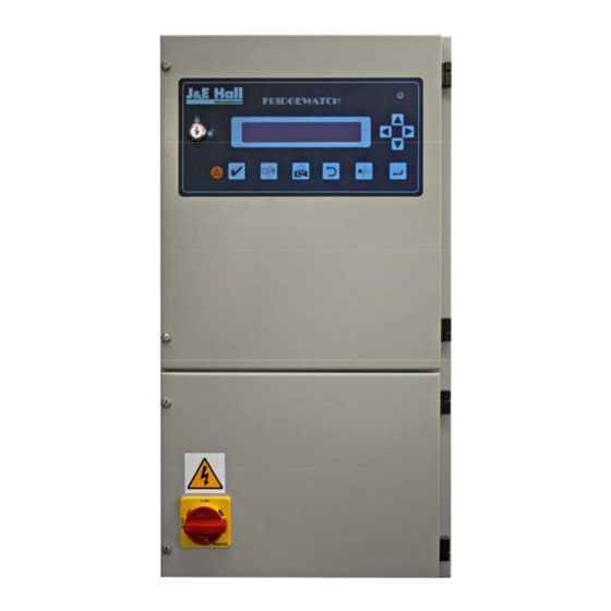
Fridgewatch 2100 Controller Mk4 Supervisor Keyswitch Mains Isolator Fig 2 Fridgewatch 2100 Mk4 Controller Section 3 Publication 3-58 Issue 1.1 : 01/08 Page 15 of 152... -
Page 16: Fig 3 Display Details
Fridgewatch 2100 Controller Mk4 Enlargement of Fridgewatch 2100 Display Button Legend Function Ref For Description ☺ Extinguishes to indicate a microprocessor fault MICRO OK ‘Flashes’ to indicate a trip event. TRIP Press to acknowledge trip event. ACKNOWLEDGE Input/change Configuration settings. -
Page 17: Fig 4 Internal Layout Of Fridgewatch 2100 Panel
FCPS1 Card; refer to Fig 16 Comp 1 Comp 2 Mains Isolator 3SCOP1 Cards; refer to Fig 17 Earth Connecting Block Fig 4 Internal Layout of Fridgewatch 2100 Panel Section 3 Publication 3-58 Issue 1.1 : 01/08 Page 17 of 152... - Page 18 RAMP4 Processor Card; refer to Fig 20 Door to Upper Half of Enclosure Door to Lower Half of Enclosure Fig 4 (continued) Internal Layout of Fridgewatch 2100 Panel - Door Mounted Items Publication 3-58 Section 3 Page 18 of 152...
-
Page 19: Fig 5 Enclosure Dimensions And Details Of Cable Entries
Fridgewatch 2100 Controller Mk4 420 mm Gland Plate 390 mm (335 mm x 110 mm) 360 mm 35 mm 40 mm 600 mm 670 mm 5 mm Mounting Hole 8 mm Diameter 150 mm 187 mm Gland Plate (230 mm x 110 mm) -
Page 20: Principles Of Control
Solenoid valves in the pipe lines supplying and venting oil to either side of the capacity slide valve piston are energised or de- energised (opened or closed) by Fridgewatch 2100 for a timed period. HallScrew 2100 and 3100 old series compressors are not fitted with an LVDT to supply a 4 to 20 mA signal;... -
Page 21: Hallscrew 3100 New Series, 3200 And 4200 Series Compressors
Solenoid valves supplying oil to the piston are energised (opened) or de-energised (closed) by Fridgewatch 2100 for a timed period. Section 3 Publication 3-58 Issue 1.1 : 01/08... -
Page 22: Proportional, Integral And Derivative (Pid) Control
The PID control algorithm allows Fridgewatch 2100 to be tuned to suit any type of control situation. Each component of the PID algorithm makes a specific and variable contribution towards limiting the control error as illustrated in Fig 7. -
Page 23: Fig 7 Proportional, Integral And Derivative (Pid) Control
Fridgewatch 2100 Controller Mk4 Temperature (°C) Fridgewatch 2100 or Pressure (bar g) Applies Maximum Corrective Control Action Steady State Error Error Proportional Band Fridgewatch 2100 Set Point Applies Corrective Action in Proportion to the Size of the Error Proportional Band Measured Value –... -
Page 24: Integral Action Time
The value for each variable can only be arrived at by subjecting Fridgewatch 2100 to system fluctuations under actual site conditions and modifying each term until the desired response is achieved. -
Page 25: Basics Of Starting And Stopping Compressors
Obviously, when controlling three compressors, Fridgewatch 2100 loads the first and second compressors in the running order to maximum before starting the third. The next compressor to start initially runs at minimum load, this is 25 %... -
Page 26: Master/Slave Operation
Fridgewatch Controller. The master and slave Fridgewatch 2100 Controllers must be wired via a changeover switch to prevent both controllers being select as master at the same time; refer to 6.7. Summary of Master/Slave Connections. -
Page 27: Starting And Stopping The Slave Compressor
Fridgewatch Controller when starting and stopping the slave compressor. However, when a master Fridgewatch 2100 Controller is linked to a slave Fridgewatch 2100 Controller controlling more than one compressor, while... -
Page 28: Compressor Running Order
1, the second compressor 2 and so on. Having established the compressor numbering designations, the running order can be set using operator setting S4 to tell Fridgewatch 2100 which is the lead compressor. Publication 3-58... -
Page 29: Fig 8 Possible Compressor Start/Stop And Capacity Control Modes
Instead of having to remember to manually change the running order, the operator can request Fridgewatch 2100 to do this automatically by setting S4 = 0. When the plant has shutdown, all compressors stopped,... -
Page 30: Capacity Control By Fridgewatch 2100
The remote controller need not be aware of the number of compressors present and only needs to send a request to load or unload because Fridgewatch 2100 deals with the rest. Publication 3-58 Section 3 Page 30 of 152 Issue 1.1 : 01/08... -
Page 31: Limiting Inputs
In addition, two digital inputs (3MIO2 terminal 133 and RAMP4 terminal 0) are provided to enable limiting from any definable plant condition which can be transmitted to Fridgewatch 2100 as a signal: contacts open or closed. Two levels of limiting can be applied by the Fridgewatch 2100 Controller:... -
Page 32: Control Strategy For Limiting Inputs
If the measured motor current exceeds the current limit 1 (inhibit loading) value defined by configuration settings S65, S68 and S71 for compressors 1, 2 and 3, Fridgewatch 2100 inhibits load pulses from the control algorithm, preventing the compressor from loading. If, however,... - Page 33 Some multi-compressor units, with integral oil separators and each compressor with its own evaporator are provided with a single Fridgewatch 2100 controller. This is likely to control on common evaporator outlet temperature but needs a means of preventing under-cooling of each individual evaporator outlet temperature.
-
Page 34: Fig 9 Limiting Inputs - Examples
Apply to All CP Discharge Pressure Limiting Compressors SP Suction Pressure Limiting Refer to connection diagrams Fig 18 to Fig 26 for Fridgewatch 2100 input/output terminal numbers. Fig 9 Limiting Inputs - Examples Publication 3-58 Section 3 Page 34 of 152... -
Page 35: Installation
Pressure transducer 0 mV to 100 mV Pressure transmitter 4 to 20 mA A 5 Ω shunt resistor must be fitted to convert the transmitter current output to a voltage input at the Fridgewatch 2100 terminals. Table 2 Transducer Inputs... -
Page 36: Digital Outputs
Temperature transducers can be supplied for tank or pipe mounting as shown in Fig 10. If transducer wiring is not long enough to reach the Fridgewatch 2100 panel, intermediate connections using local terminals boxes may be necessary. -
Page 37: Fig 10 Transducer Installation
Fridgewatch 2100 Controller Mk4 Pressure Transducer Connection ¼” BSP to 6 mm Compression Fitting 6 mm Suction Pressure Compression Dowty Gauge Fitting Seal Gauge Valve Pressure 6 mm Wire to Transducer Gauge Line Fridgewatch Framework 6 mm Gauge Line Wire to... -
Page 38: Power Supply Connections (Lower Half Of Enclosure)
Reverse bias Relay diode type Black 1N4004 NOTE: the diode MUST be connected as shown, otherwise Fridgewatch 2100 may be seriously damaged. Fig 11 Connecting Diodes 6.4. Power Supply Connections (Lower Half of Enclosure) The Fridgewatch 2100 Controller will normally be supplied already mounted on the package unit. -
Page 39: Opto-Electronic Liquid Sensor Interface Unit
Fig 4 shows the relative position of the cards. In the wiring connection illustrations the terminal numbers are prefixed according to the position of the card in the Fridgewatch 2100 panel; refer to Table 4. 6.5.4. -
Page 40: Fig 12 Economiser Arrangements: Wiring To Liquid Line Solenoid Valves
Fridgewatch 2100 Controller Mk4 Discharge Suction TEV Equalising Line Equalising Evaporator Line Economiser Separator Typical Single Compressor Application Economiser Liquid Line Evaporator Liquid Line 185A Solenoid Valve Solenoid Valve Condenser Comp 2 Comp 3 Comp 1 185A 285A 385A Economiser... -
Page 41: Fridgewatch Highway Connections
6.6. Fridgewatch Highway Connections If it is required to connect the Fridgewatch 2100 Controller to a PC or SCADA system via the Fridgewatch Highway, optional module LCC3 is required; connection details are shown in Fig 13. The LCC3 module is located on the DIN rail inside the Fridgewatch panel. -
Page 42: Summary Of Master/Slave Connections
B52 input/output cards. If these cards are fitted to either Fridgewatch Controller, contact J & E Hall International. A Fridgewatch 2100 Controller controlling one compressor must be fitted with a 3MIO2 card to permit master/slave operation. Operator setting S19 must be set to 1 on both master and slave Fridgewatch Controllers. -
Page 43: Fig 14 Wiring Connections For Master/Slave Without External Run Request Or Run Enable Signal
Fridgewatch 2100 Controller Mk4 2100 2100 RIDGEWATCH RIDGEWATCH OMPRESSOR OMPRESSOR 2 and 5 Pair 0.5 mm Screened Cable Compressor B Master/Compressor A Slave RAMP (+) RAMP 4 1 Pair 0.5 mm RAMP (+) Screened Cable RAMP 4 1 Pair 0.5 mm... -
Page 44: Fig 15 Wiring Connections For Master/Slave With External Run Request Or Run Enable Signal
Fridgewatch 2100 Controller Mk4 2100 2100 RIDGEWATCH RIDGEWATCH OMPRESSOR OMPRESSOR 5 Pair 0.5 mm Screened Cable Compressor B Master/Compressor A Slave RAMP (+) RAMP 4 RAMP (+) RAMP 4 External Run Enable or Run Request Contacts (by others) 4 Pair 0.5 mm 4 Pair 0.5 mm... -
Page 45: Cards And Wiring Connections
Fridgewatch 2100 Controller Mk4 Cards and Wiring Connections 7.1. FCPS1 Power Supply Card Bottom entry to enclosure. PURPLE RED YELLOW ORANGE BLACK BLACK BLACK +5 V +24 V +24 V KS WHITE Protective Cover Jumper, Set to Supply Voltage L N K K FS1 protects V for digital outputs and analogue inputs, RS232 and RAMP4 digital inputs. -
Page 46: 3Scop1 Relay Outputs Card
Fridgewatch 2100 Controller Mk4 7.2. 3SCOP1 Relay Outputs Card Bottom entry to enclosure. 81 83 79 85 85A 87 89 91 93 80 82 78 84 84A 86 88 90 92 NOTE: when handling electronic cards, the precautions detailed in 2.1. Anti- Static Precautions must be taken. -
Page 47: Fig 18 Wiring Connections To 3Scop1 Relay Outputs Card For Compressor 1
Terminals 185, 185A and 187 share one 8 Amp/3 Amp contact. If Fridgewatch 2100 controls more than one compressor package unit, each with its own oil separator/reservoir and oil heaters, DO NOT use terminals 180 to 183 to control the oil heaters; use a secondary contact from each individual compressor motor contactor. -
Page 48: Fig 19 Wiring Connections To 3Scop1 Relay Outputs Card For Compressors 2 And 3
Fridgewatch 2100 Controller Mk4 UNCTION ERMINALS EMARKS 240/110 V ac DO NOT use these terminals. 240/110 V ac DO NOT use these terminals. 240/110 V ac DO NOT use these terminals. Oil Line Solenoid Valve Energise (open) when the compressor starts, 240/110 V ac de-energise (close) when the compressor stops. -
Page 49: Fig 20 Ramp4 Processor Card
Fridgewatch 2100 Controller Mk4 1 B 2 JM1 and JM2 Connectors Lithium for RS232 Ports Battery Clock Jumper Set to 1-B to Enable Battery RAM (Battery Backed) RS232 Printer Port RAM (Battery Backed) RS232 Terminal Port Fridgewatch Software Jumper set to 1-W to Enable Watchdog... -
Page 50: Fig 21 Anp8 Display Card + Display
Fridgewatch 2100 Controller Mk4 J2 Display Connector (on back of card) Contrast Micro OK Alarm ANP8 Display Card For display details refer to Fig 3 Display NOTE: when handling electronic cards, the precautions detailed in 2.1. Anti-Static Precautions must be taken. -
Page 51: Fig 22 Wiring Connections To Ramp4 Processor Card
A remote terminal or printer must either have its RS232 ports isolated from ground or the mains power supply to the terminal or printer must be from the same phase supplying the Fridgewatch 2100 panel. Failure to observe this precaution may seriously damage the Fridgewatch 2100, terminal or printer. -
Page 52: Fig 23 3Mio1 Input/Output Card For Compressor 1
Fridgewatch 2100 Controller Mk4 P1 (Analogue Input 1) - Temperature P2 (Analogue Input 2) - Pressure or Temperature After connecting transducers to analogue inputs, Zero Z and Scale P4 (Analogue Input 3) - 4 to G potentiometers must 20 mA for Slide Valve LVDT be adjusted. -
Page 53: Fig 24 Wiring Connections To 3Mio1 Input/Output Card For Compressor 1
Fridgewatch 2100 displays a trip: event code E2 High Discharge Temperature. Terminal prefix: 1 = compressor 1, the card positioned in the Fridgewatch 2100 enclosure immediately adjacent to the mounting board; refer to Fig 4. This prefix does not physically appear on the card. - Page 54 Terminal prefix: 1 = compressor 1, the card positioned in the Fridgewatch 2100 enclosure immediately adjacent to the mounting board; refer to Fig 4. This prefix does not physically appear on the card.
- Page 55 Fig 14 and Fig 15. Common Terminal prefix: 1 = compressor 1, the card positioned in the Fridgewatch 2100 enclosure immediately adjacent to the mounting board; refer to Fig 4. This prefix does not physically appear on the card.
- Page 56 Sent by master. Start the slave Terminal prefix: 1 = compressor 1, the card positioned in the Fridgewatch 2100 enclosure immediately adjacent to the mounting board; refer to Fig 4. This prefix does not physically appear on the card. If fitted, depends on the application.
-
Page 57: Fig 25 3Mio2 Input/Output Card For Compressors 2 And 3
Fridgewatch 2100 Controller Mk4 P4 (Analogue Input 1) - 4 to 20 mA for Slide Valve LVDT After connecting P5 (Analogue Input 2) - transducers to Compressor Motor Current analogue inputs, Zero Z and Scale G potentiometers must be adjusted. -
Page 58: Fig 26 Wiring Connections To 3Mio2 Input/Output Card For Compressors 2 And 3
Check jumper connection J14 on the 3MIO2 card; refer to Fig 25. HP Cut-out HP cut-out contacts open on fault condition. Fridgewatch 2100 displays a trip: event code E6 HP Cut-out. Check jumper connection J16 on the 3MIO2 card; refer to Fig 25. - Page 59 UNCTION ERMINALS EMARKS LP Cut-out LP cut-out contacts open on fault condition. Fridgewatch 2100 displays a trip: event code E5 LP Cut-out. Check jumper connection J18 on the 3MIO2 card; refer to Fig 25. Oil Low Level Opto-Electronic Liquid Sensor...
- Page 60 Auxiliaries Motor Starter Operation 24 V dc low consumption relay mounted in the auxiliary starter. Fridgewatch 2100 will energise this relay to start auxiliaries. A ‘running’ signal should be Auxiliary start returned to Fridgewatch via volt-free contacts in the output relay starter that close when the auxiliary starts and runs.
- Page 61 Fridgewatch 2100 Controller Mk4 UNCTION ERMINALS EMARKS From Another Fridgewatch 2100 or 2000 Digital Inputs From Another FW 2100 or 2000 Controller in Master/Slave Configuration Controller in Master/Slave Configuration: S19 = 1 Link 235 = Link terminals 235 and 236.
-
Page 62: User Interface
Fridgewatch 2100 Controller Mk4 User Interface The Fridgewatch 2100 Controller panel, illustrated in Fig 2 and Fig 3, comprises a 4 line 40 character LCD display plus a series of operator input buttons. Some of the operator inputs are restricted by use of the Supervisor Key. -
Page 63: Fig 27 Menu Structure
Fridgewatch 2100 Controller Mk4 Use the HOME PAGE button to toggle between the Home and Contents pages. Use the navigation buttons to scroll through menu pages. Comp 1 Running SVP:Low Lead Comp 2 (Displayed if S42 = 2, FW2100 controls 2 compressors) Home Page Comp 3 (Displayed if S42 = 3, FW2100 controls 3 compressors) °... -
Page 64: Contents
There are two types of setting: • Configuration settings S41/S117: affect the way Fridgewatch 2100 interfaces with the refrigeration plant and must be entered before starting the plant for the first time. They may be viewed (but not modified) at any time thereafter by selecting the Configuration Settings page. -
Page 65: Status Indicators
Micro Ok ☺ MICRO OK With power supplied to the Fridgewatch 2100 Controller and the main isolator turned to the ‘on’ position, MICRO OK should be illuminated. If the indicator extinguishes, this indicates a microprocessor fault which cannot be corrected by the Watchdog. -
Page 66: Configuration Settings
Fridgewatch 2100 Controller Mk4 8.8.2. Configuration Settings CONFIGURATION SETTINGS Use with the Supervisor Key to input configuration settings during commissioning or changing the value of a configuration setting afterwards; refer to 9.4. and 9.6. 8.8.3. Home Page HOME PAGE Press to return to the Home page from any menu page. -
Page 67: Scroll Up - Raise Setting - Start/Load Compressor (Manual Control Only)
(if available to start). In a master/slave configuration, when all the compressors controlled by the master Fridgewatch 2100 Controller have reached maximum capacity, a further press of the button starts the first compressor in the slave compressor running order (if available to start). -
Page 68: Lower Setting - Unload Compressor (Manual Control Only)
Fridgewatch 2100 Controller Mk4 8.8.8. Lower Setting – Unload Compressor (Manual Control Only) LOWER SETTING – UNLOAD COMPRESSOR (MANUAL CONTROL ONLY) In common with the button, the button has three separate functions. With the Supervisor Key in the Locked position the navigation button is used to scroll through the menu pages. - Page 69 Under no circumstances will J & E Hall International accept responsibility for damage to plant or injury to personnel caused by unauthorised use of the Fridgewatch 2100 Controller Supervisor Key. Section 3 Publication 3-58 Issue 1.1 : 01/08 Page 69 of 152...
-
Page 70: Commissioning
Fridgewatch 2100 Controller Supervisor Key. 9.2. Checks to be Made Prior to Supplying Power to Fridgewatch 2100 • Check the position of the supply jumper on the FCPS1 power supply card corresponds to the supply voltage, 240 V or 110 V;... -
Page 71: Transducer Calibration And Potentiometer Adjustment
When power is first supplied to the Fridgewatch 2100 Controller, the display shows ‘System Unconfigured’, ‘Restart system and enter Configuration Mode’, the panel is locked and none of the input buttons will operate. -
Page 72: Fig 28 Looking At Or Changing Configuration Settings
Fridgewatch 2100 Controller Mk4 Use the navigation buttons to move around the menu pages. CONTENTS To Look at a Measured Points Mode Selection Configuration Operator Settings Config Settings Setting Info Press the HOME PAGE button followed by the ENTER button to select the Contents page. - Page 73 Fridgewatch 2100 Controller Mk4 Config Settings (current date and time) S41 Number of Comps S42 Number of First Comp S43 P1 Pt100 3MIO1 Used The Configuration Settings page is displayed. Use the buttons to select the setting to be changed (S52 in this example).
-
Page 74: Inputting Operator Settings During Commissioning
‘off’ mode; refer to 9.7. Changing the Operating Mode. If the compressor is not running, wait at least 10 seconds to make sure Fridgewatch 2100 has accepted the mode change. If the compressor is already running it should stop and be inhibited from restarting. -
Page 75: Fig 29 Looking At Or Changing Operator Settings
Fridgewatch 2100 Controller Mk4 Use the navigation buttons to move around the menu pages. CONTENTS To Look Measured Points Mode Selection at an Operator Operator Settings Config Settings Setting Info Press the HOME PAGE or PREVIOUS MENU buttons to select the Contents page. -
Page 76: Changing The Operating Mode
– ‘manual’ capacity control mode; refer to 9.4.3. Operating Mode for the First Start. If the Fridgewatch 2100 Controller is not to be run in Master/Slave configuration but is subject to a central controller, for example, a Fridgewatch Auto Controller or System Controller, Operator Setting S19 Master/Slave Connected can be set to provide a digital output indicating the operating mode;... -
Page 77: Printing Or Downloading The Settings List
Set S34 Printer Selected to 1; refer to 9.5. Changing Operator Settings after Commissioning. If there is a printer already attached to Fridgewatch 2100, S34 Printer Selected will already be set to 1. Display Operator Settings. Turn the Supervisor Key to the Unlocked position. -
Page 78: Event Codes
These event codes provide details of trip events which stop the compressor or prevent it from starting. When a trip event occurs, Fridgewatch 2100 stops the compressor if it is already running and prevents the compressor restarting unless the trip condition has been cleared and Fridgewatch reset. -
Page 79: Fig 31 Identifying And Clearing Trip Events, Reasons For Normal Stop And Reason For Trip
‘compressor healthy’ digital output from ‘off’ to ‘on’. Restart the compressor, if appropriate. Example: The Fridgewatch 2100 Controller has tried and failed to return the compressor slide valves to minimum load during the start sequence. Start aborted. Comp 1 E08 Compressor Failed to Unload ... -
Page 80: Event Codes Description
Event Codes Description This part of the manual provides a full description of each event code which may appear on the front panel of the Fridgewatch 2100 Controller Mk4. A quick-reference of all event codes may be found in 15. Appendix 2 - Event Codes E1/E47 Quick-Reference. - Page 81 Remarks: The Home Page indicates which compressor has tripped. Check the refrigeration system as described in the plant instruction manual. Also check the Fridgewatch 2100 Controller stop value(s) and the suction pressure limiting system (if fitted). Cause 2: Fuse FS2 blown; refer to Fig 16.
- Page 82 Compressor Failed To Unload: Trip, Compressor Healthy Off, Manual Reset This event code is implemented for all applications. Cause: The Fridgewatch 2100 Controller has tried and failed to return the compressor slide valves to minimum load, i.e. the minimum position switch contacts are open. Remarks: The Home Page indicates which compressor has tripped.
-
Page 83: Table 5 E14 High Or Low P6 (Pressure Or Temperature)
Fridgewatch 2100 Controller Mk4 E10 and E11 Not Used E12 Low P1 (Temperature): Trip, Compressor Healthy Off, Manual Reset This event code is implemented if P1 is enabled for limiting and trips by setting Configuration Setting S90 to a non-zero value. - Page 84 Manual Reset This event code is implemented for all applications. Cause: When Fridgewatch 2100 sends a start signal to the auxiliaries starter, a ‘running’ signal must be returned to Fridgewatch within the limit set by S50 Auxiliaries Start Time. Remarks: Check the auxiliaries starter operation and running interlocks.
- Page 85 Fridgewatch 2100 Controller Mk4 Remarks: Check the auxiliaries starter operation and running interlocks. E35 to E40 Not used E41 P1 (Temperature Input on 3MIO1 Card) Over-range or Failed This event code is implemented when a 4-wire temperature transducer is connected to analogue input 1 on the 3MIO1 card; refer to Fig 24. E41 becomes a trip (compressor healthy off, manual reset) if P1 is being used for a control, limiting or trip function.
- Page 86 Fridgewatch 2100 Controller Mk4 Remarks: As a result of this failure the following inputs may not be read correctly: x25, x30, x31, x32, x34, x37, x38 and x39. E46 P4 (LVDT Input) Over-range or Failed This event code is implemented when a transmitter is connected to...
-
Page 87: Settings
These settings will initially be determined by the commissioning engineer, but as certain values may need to be altered later, they can be changed from the Fridgewatch 2100 panel using the Supervisor Key and Settings mode. Operator settings can be changed at any time, even while the compressor is running. -
Page 88: Table 6 Determining Compressor Running Order Priority
Compressor 2 → Compressor 3 → Compressor 1 Compressor 3 → Compressor 1 → Compressor 2 Running order determined by Fridgewatch 2100 based on number of hours run Table 6 Determining Compressor Running Order Priority Proportional band (units: pressure in bar or temperature in °C) This is the deviation from the set point resulting in the maximum possible capacity change to the compressor. - Page 89 Fridgewatch 2100 Controller Mk4 Before making alterations to S5 Proportional Band, S6 Integral Action Time or S7 Derivative Action Time, it is essential to have read and understood the notes under 5. Principles of Control. Derivative action time (units: second) This is the time, in seconds, required for the proportional action to equal the derivative action, given a ramp change in demand.
- Page 90 Fridgewatch 2100 Controller Mk4 S12 only comes into effect when ‘auto’ capacity control mode is selected. This setting is ignored in all other modes, including a Fridgewatch 2100 Controller acting as the slave in a master/slave configuration. S13 Set point deviation to stop next compressor (units: pressure in bar g or temperature in °C)
-
Page 91: Table 7 Run Enable Required In Different Operating Modes - Values For S14
As S16 but applied to compressor 3. S19 Master/slave connected or operating mode indication If this Fridgewatch 2100 is connected in a master/slave configuration with another Fridgewatch 2100 or 2000 Controller, S19 for both Fridgewatch Controllers must be set to 1. -
Page 92: Table 8 Operating Mode Indication Using Setting S19
Commissioning. S20 Two start value/set point/stop value sets required The Fridgewatch 2100 Controller provides the facility to toggle or slide between two different sets of control values: No 1 start value, No 1 set point and No 1 stop value, and No 2 start value, No 2 set point and No 2 stop value. - Page 93 S23 No 1 start value (units: pressure in bar g or temperature in °C) When operating in ‘auto start/stop’ mode, this is the value of temperature or pressure which Fridgewatch 2100 uses to start the compressor when No 1 start value/set point/stop value set is in force.
-
Page 94: Fig 32 Flowchart To Assist In Adjusting Start Value/Set Point/Stop Value Times
Fridgewatch 2100 Controller Mk4 Number of One Value Set Set S20 = 0 (default) START value sets A change to S1, S2 or S3 changes corresponding S21, S23 or S25. Two Value Sets A change to S21, S23 or S25 changes corresponding S1, S2 or S3. - Page 95 Fridgewatch 2100 Controller Mk4 S26 is only used when two different start value/set point/stop value sets are required (S20 > 0). S27 The time when to switch from No 1 to No 2 start value/set point/stop value set (units: 24 hour clock: hour and 1/10 of...
-
Page 96: Table 9 Initial Load Values On Starting
The initial load values available are illustrated in Table 9. S33 Terminal select Set to 1 if a VDU terminal is attached directly to Fridgewatch 2100 and a regularly updated (every 30 seconds) display is required. Use the default value of 0 if not required. - Page 97 1, 2 or 3 irrespective of setting S42. The value of S39 remains unaltered unless another trip occurs, even if the Fridgewatch 2100 isolator is turned to ‘off’ or the power supply interrupted. This means that even if the reason for the trip is cleared and the compressor is restarted, there is a record of the reason for the trip.
-
Page 98: Configuration Settings S41/109
Fridgewatch 2100 and hence the number of input/output cards (one for each compressor). If S41 = 0, when power is first supplied to the Fridgewatch 2100 Controller, the display shows ‘System Unconfigured’, ‘Restart system and enter Configuration Mode’, the panel is locked and none of the input... -
Page 99: Table 10 Transducer/Transmitter Types And Ranges
100 mV Gauge Pressure Transmitter 4 to 20 mA, 0 to +(RANGE) bar g With a 5 Ω shunt resistor fitted across the terminals. at 4 mA = 20 mV across Fridgewatch 2100 terminals. Fridgewatch 2100 displays RANGE at 20 mA = 100 mV across Fridgewatch 2100 terminals. - Page 100 (S49) value. A typical value for S49 is 4, the default setting, permitting 1 start every 15 minutes. It Fridgewatch 2100 is waiting for the starts per hour timer to expire, Wait S49 SPH Timer appears in the display with a countdown TTS:xxxxs.
-
Page 101: Table 11 Swept Volumes Of Hallscrew Compressors
Fridgewatch 2100 Controller Mk4 S53 Enhancement factor for compressor 1 When the Fridgewatch 2100 is required to control compressors of different capacities, this scaling factor ensures that the output from the control algorithm provides a similar response regardless of which compressor is being controlled. - Page 102 Fridgewatch protocol or Modbus RTU protocol. If the value of S61 is positive or zero, the Fridgewatch 2100 Controller configures itself to the Fridgewatch protocol; the Fridgewatch address used being the value of S61. A value of 0 (zero) is used for testing purposes and causes Fridgewatch 2100 to reply to all addresses (1 to 26 inclusive).
- Page 103 4200 series compressors provides a 4 to 20 mA signal but without means of calibration on the LVDT. Calibration of P4 is done in Fridgewatch software, i.e. Fridgewatch 2100 needs to be told when the 4 to 20 mA signal corresponds to minimum and maximum slide valve position.
-
Page 104: Table 12 Capacity Control Valve Application And Operation
Fridgewatch 2100 Controller Mk4 2100 3SCOP1 R RIDGEWATCH ELAY HANNELS CREW OMPRESSOR ERIES ERMINAL AIRS 1, 3 : 2 S NC (S62 = 0) OLENOID ALVE OLENOIDS OLENOID OLENOID HS 18 to HS 235 APACITY ONTROL CTION 2100 Series: 2000 Series:... -
Page 105: Table 13 Slide Valve Position Indication For Hallscrew Compressors
Fridgewatch 2100 Controller Mk4 20 mA S LIDE ALVE WITCHES TO NDICATE LIDE CREW OMPRESSOR ERIES OSITION IGNAL ALVE OSITION Compressors serial numbers 4 to 20 mA signal from Microswitches for minimum, HS 18 to HS 235 95151-XXX-XXX potentiometer (gear driven) -
Page 106: Table 14 Slide Valve Position Options - Values For S63
LVDT and the normal range of P4 calibration is not sufficient. Refer to the limitations described in the NOTE below. NOTE The single value of S63 applies to ALL compressors controlled by a single Fridgewatch 2100 panel. This results in two limitations: 1) For multiple compressors connected to one Fridgewatch 2100 panel, if ONE compressor uses the LVDT 4 to 20 mA signal on P4 for slide valve position, ALL compressors must use P4 for slide valve position. - Page 107 S68 and S69. 4 to 20 mA signal from a motor soft-starter or inverter. Fit a 50 Ω shunt resistor across the Fridgewatch 2100 input and set S67 = -1 x motor line current (not phase current) corresponding to the 20 mA signal.
- Page 108 S71 and S72. 4 to 20 mA signal from a motor soft-starter or inverter. Fit a 50 Ω shunt resistor across the Fridgewatch 2100 input and set S70 = -1 x motor line current (not phase current) corresponding to the 20 mA signal.
-
Page 109: Table 15 Values For S75 To S80 Current Date And Time
Table 15 Values for S75 to S80 Current Date and Time S81 Update internal clock This setting is used to initiate an update to the Fridgewatch 2100 Controller internal clock. Set S81 to 0, Fridgewatch ignores clock settings S75 to S80. the default value is 0. - Page 110 Fridgewatch 2100 Controller Mk4 Enter configuration mode. Make changes, if required, to Configuration Settings S41 to S74, i.e. other than S75 to S81 which update the date/time. Last of all, step through S75 to S80 updating the date and/or time as required. IMMEDIATELY after altering the minutes value (S80), step to S81, change the setting to 1 (to update the clock) and return the Supervisor Key to the Locked position.
- Page 111 Fridgewatch 2100 Controller Mk4 Set S83 to 1 for applications where each compressor has its own oil separator fitted with an oil level switch or opto-sensor conditioning relay connected across terminals x19/x20 on the compressor 3MIO1 and 3MIO2 cards. In this case: •...
- Page 112 S89 P4 trip: trip limit (units: as defined by S84/S85) With S86 enabled, S89 defines the temperature or pressure limit at which the Fridgewatch 2100 stops the plant and displays a trip: event code E14 High or Low P4 (Pressure or Temperature). The Home Page indicates which compressor has tripped.
- Page 113 Fridgewatch 2100 Controller Mk4 Example: use of S63, S84, S85, S86, S87, S88 and S89 25 bar g 4 to 20 mA pressure transmitters sensing discharge pressure are wired into the P4 analogue inputs. Settings: S63 = 2, S84 = 0 bar g, S85 = 25 bar g, S86 = -2 bar g, S87 = 15 bar g, S88 = 17 bar g, S89 = 30 bar g.
- Page 114 P1 is normally used for a common control temperature, for example, chilled water outlet from a common evaporator. P1 limits apply in all operating modes and: • If no compressors are running - Fridgewatch 2100 will inhibit starting and Limiting appears on the front panel display for all compressors;...
- Page 115 S93 P1 (temperature) trip: trip low limit (units: °C) With S90 enabled, S93 defines the low temperature limit at which the Fridgewatch 2100 Controller stops the plant and displays a trip: event code E12 Low P1 (Temperature). NOTE: the value assigned to S93 Trip Low Limit must normally be lower than the S92 Unload Low Limit.
- Page 116 ‘manual’ start/stop - ‘manual’ capacity control mode Fridgewatch 2100 will trip the compressor. In ‘manual’ mode limiting is normally applied, but when an...
- Page 117 S97 P2 (pressure) trip: trip low limit (units: bar g) With S94 enabled, S97 defines the low pressure limit at which the Fridgewatch 2100 Controller stops the plant and displays a trip: event code E13 Low P2 (Pressure). NOTE: the value assigned to S97 Trip Low Limit must normally be lower than the S96 Unload Low Limit.
- Page 118 Table 13 and Table 14, use S98 = 0 and S99 = 0 and ignore the following paragraphs. The Fridgewatch 2100 Controller uses setting S98 to estimate whether sufficient successive load pulses have been issued to move the slide valve to the maximum load position for compressors with no slide valve position detectors fitted.
- Page 119 If S100 is set from 1 to 10 seconds, this timer is ignored. If S100 is set from 10 to 30 seconds, the auxiliaries running input can be off for a period up to the value of S100 before Fridgewatch 2100 displays a trip: event code E34 Auxiliaries Lost Running Signal.
- Page 120 Fridgewatch 2100 Controller Mk4 S105 Load pulse duration on compressor 3 (units: second) As for settings S101 and S103 but for compressor 3. S106 Unload pulse duration on compressor 3 (units: second) As for settings S102 and S104 but for compressor 3.
- Page 121 Fridgewatch 2100 Controller Mk4 S115 P4 value for minimum load (units: %) If the compressor is fitted with an LVDT providing a 4 to 20 mA signal for slide valve position (SVP) or compressor pumping capacity is modulated via a variable speed drive providing a 4 to 20 mA signal for motor speed, S63 is set to 3 or 4.
-
Page 122: Maintenance
A full transducer calibration check is recommended every 5 years. The lithium battery used to back up Fridgewatch 2100 settings should be checked after 5 years, then every year until the battery needs replacing; refer to 12.7. Checking and Replacement of Lithium Back-up Battery. -
Page 123: Calibration Of Temperature Transducers
Stir the ice continuously for two minutes and check with the thermometer that the water temperature is at 0°C. Set the Fridgewatch 2100 Controller front panel to display the measured point under test. The DISPLAY should read 0.00 °C ±0.02 °C. -
Page 124: Calibration Of Motor Current
Stop the compressor(s) by pressing the STOP COMPRESSORS (ALL MODES) button. Set Fridgewatch 2100 to display motor current (P5) for compressor Adjust the motor current Zero ZD potentiometer on the 3MIO1 card for compressor 1 until 0 amps is displayed. -
Page 125: Calibration Of Lvdt 4 To 20 Ma Signal - Hs 2000 Series Compressors
Fridgewatch 2100 panel by use of S16, S17 and S18 Compressor Availability. If Fridgewatch 2100 is controlling more than one compressor, disable this compressor and enable the next using S16, S17 and S18. Repeat the procedure described in Fig 33 for the next compressor. -
Page 126: Fig 33 Calibration Of Lvdt 4 To 20 Ma Signal - Hs 3100 New Series, Hs 3200 And Hs 4200 Series Compressors
Turn the Supervisor Key to the Locked position to ‘fix’ the minimum calibration, i.e. tell Fridgewatch 2100 that the signal it is currently receiving into the P4 analogue input is the value it should interpret as the minimum load position and display 0 %. An arrow ← appears to the right of the value to indicate that the calibration has been fixed. - Page 127 Observe monitoring point P3 on the Fridgewatch 2100 display and make a note of the number of hours the compressor has run. Stop the plant. Turn off the power supply to the Fridgewatch 2100 by turning the main isolator on the lower control panel door to the ‘off’...
-
Page 128: Checking And Replacement Of Lithium Back-Up Battery
Fig 20. The battery provides the power required to maintain RAM memory of Fridgewatch 2100 setting data when Fridgewatch is switched off or in the event of a mains power supply failure. A healthy, fully charged battery should retain memory in the processor for at least 6 months. -
Page 129: Spares
RS 419-779 heater heater (if fitted) anti-surge (T) Mains input Fridgewatch 2100 Mk4 panels are fitted with a miniature circuit breaker (MCB) instead of a fuse Table 17 Fuses 13.2. Electronic Cards, Conditioning Units and Modules J & E H... -
Page 130: Appendix 1 - Measured Points Reference
Fridgewatch 2100 Controller Mk4 Appendix 1 - Measured Points Reference OSSIBLE PPLICATION OINT BBREVIATED ESCRIPTION ESCRIPTION NITS °C Temp Measured temperature Press Measured pressure bar g Hrs Run Hours run hour x 10 Slide valve position Motor Motor current Most common use shown. -
Page 131: Appendix 2 - Event Codes E1/E47 Quick-Reference
Fridgewatch 2100 Controller Mk4 Appendix 2 - Event Codes E1/E47 Quick-Reference VENT BBREVIATED ESCRIPTION ESCRIPTION High Motor Temp High motor temperature High Discharge Temp High discharge temperature E3 Not used Low Oil Level in Sep/Res Low oil level in separator/reservoir... - Page 132 Fridgewatch 2100 Controller Mk4 IRING ONNECTIONS VENT ESET SSOCIATED ETTING ERMINALS x09/x10 3MIO1 or Trip Manual 3MIO2 x13/x14 E3 Not used X19/x20 X17/x18 3MIO1 or 3MIO2 X15/x16 Trip Manual x21/x22 E10 and E11 Not used S90/S93 Anin 1 101/104 3MIO1...
-
Page 133: Appendix 3 - Settings Record
Fridgewatch 2100 Controller Mk4 Appendix 3 - Settings Record During the commissioning period, the default Operator and Configuration Setting values are modified by the commissioning engineer to achieve optimum plant control and efficiency. The final settings values, arrived at on completion of commissioning, must be recorded in this part of the manual for future reference. - Page 134 Fridgewatch 2100 Controller Mk4 2100 O S1/S39 RIDGEWATCH PERATOR ETTINGS BBREVIATED ESCRIPTION ESCRIPTION Set Point Set point Start Value Start value Stop Value Stop value Lead compressor number Lead compressor number Proportional Band Proportional band Integral Action Time Integral action time...
- Page 135 Fridgewatch 2100 Controller Mk4 PERATOR ETTING NPUT ALUES & D ANGE EFAULT OMPRESSOR OMPRESSOR OMPRESSOR min = -99.90 bar g or °C default = +1.50 max = +80.00 min = -99.90 bar g or °C default = +2.00 max = +80.00 min = -99.90...
- Page 136 Fridgewatch 2100 Controller Mk4 2100 O S1/S39 RIDGEWATCH PERATOR ETTINGS M/S Connected – OP Mode Master/slave connected or operating mode indication Two Set Point Sets Reqd Two start value/set point/stop value sets required No 1 Set Point No 1 set point...
- Page 137 Fridgewatch 2100 Controller Mk4 PERATOR ETTING NPUT ALUES & D ANGE EFAULT OMPRESSOR OMPRESSOR OMPRESSOR min = -4 default = 0 max = +2 min = 0 default = 0 max = 2 min = -99.90 bar g or °C default = +1.50...
- Page 138 Fridgewatch 2100 Controller Mk4 2100 C S41/S117 RIDGEWATCH ONFIGURATION ETTINGS Number of Comps Number of compressors Number of First Comp Number of the first compressor controlled by FW2100 P1 (Pt 100 Ω analogue input 1 on 3MIO1 card): unused/used P1 Pt100 3MIO1 Used...
- Page 139 Fridgewatch 2100 Controller Mk4 PERATOR ETTING NPUT ALUES & D ANGE EFAULT OMPRESSOR OMPRESSOR OMPRESSOR min = 0 default = 1 max = 3 min = 1 default = 1 max = 9 min = 0 default = 0 max = 2...
- Page 140 Fridgewatch 2100 Controller Mk4 2100 C S41/S117 RIDGEWATCH ONFIGURATION ETTINGS Start-up Load Time/Posn Start-up load time or position Sample time Sample time Modbus/FW Highway Address Modbus or Fridgewatch Highway station address Cap Control Valve Type C1 Capacity control valve type on compressor 1...
- Page 141 Fridgewatch 2100 Controller Mk4 PERATOR ETTING NPUT ALUES & D ANGE EFAULT OMPRESSOR OMPRESSOR OMPRESSOR min = 0 second default = 0 max = 240 min = 15 default = 30 second max = 300 min = -256 default = +26...
- Page 142 Fridgewatch 2100 Controller Mk4 2100 C S41/S117 RIDGEWATCH ONFIGURATION ETTINGS Month (Jan=01) Month Year Year Hour (24hr clock) Hour Minute Minute Update internal clock Update internal clock Energise O/Ps 243/343 @ Start Energise outputs 243 and 343 on starting first compressor...
- Page 143 Fridgewatch 2100 Controller Mk4 PERATOR ETTING NPUT ALUES & D ANGE EFAULT OMPRESSOR OMPRESSOR OMPRESSOR min = 1 month default = n (as a number) max = 12 min = 0 year default = n (last two digits) max = 99...
- Page 144 Fridgewatch 2100 Controller Mk4 2100 C S41/S117 RIDGEWATCH ONFIGURATION ETTINGS P2 Pr Hold Low Limit P2 (pressure) limiting: hold low limit P2 Pr U/L Low Limit P2 (pressure) limiting: unload low limit P2 Pr Trip Low Limit P2 (pressure) trip: trip low limit Estimated number of pulses to move slide valve from minimum to Est Pulses SVP Min ->...
- Page 145 Fridgewatch 2100 Controller Mk4 PERATOR ETTING NPUT ALUES & D ANGE EFAULT OMPRESSOR OMPRESSOR OMPRESSOR min = -99.90 bar g default = 0.00 or °C max = +99.90 min = -99.90 bar g default = 0.00 or °C max = +99.90 min = -99.90...
- Page 146 Fridgewatch 2100 Controller Mk4 2100 C S41/S117 RIDGEWATCH ONFIGURATION ETTINGS S113 Stop Bits Stop Bits S114 Parity Parity S115 P4 LVDT Min Load Value P4 value for minimum load S116 Econ Sol On At LVDT Value Economiser solenoid valve energises at LVDT value...
- Page 147 Fridgewatch 2100 Controller Mk4 PERATOR ETTING NPUT ALUES & D ANGE EFAULT OMPRESSOR OMPRESSOR OMPRESSOR min = 1 S113 default = 1 max = 2 min = 0 S114 default = 2 max = 2 min = 10 S115 default = 10...
-
Page 148: Appendix 4 - Start-Up Timing Diagram
Appendix 4 - Start-up Timing Diagram Fig 34 show the sequence of events as a HallScrew compressor starts under the control of a Fridgewatch 2100 Controller Mk4. This is the only sequence approved by J & E Hall International. Time Start point: i.e. - Page 149 Remote signals received prior to this are ignored. If Fridgewatch 2100 controls more than one compressor on a common oil separator/reservoir, the oil heaters de-energise when the first compressor starts, re-energise when the last compressors stops. If Fridgewatch 2100 controls more than one compressor package unit each with its own oil separator/reservoir and oil heaters, DO NOT use terminals 180, 181 and 183 to control the oil heaters;...
-
Page 150: Index
Fridgewatch 2100 Controller Mk4 Index Publication 3-58 Section 3 Page 150 of 152 Issue 1.1 : 01/08... - Page 151 Fridgewatch 2100 Controller Mk4 This page intentionally blank Section 3 Publication 3-58 Issue 1.1 : 01/08 Page 151 of 152...
- Page 152 Fridgewatch 2100 Controller Mk4 ©J & E Hall International 2008 All rights reserved. No part of this publication may be reproduced or transmitted in any form or by any means, electronic or mechanical, including photocopying, recording or by any information storage or retrieval system, without permission in writing from the copyright holder.
Need help?
Do you have a question about the Fridgewatch 2100 and is the answer not in the manual?
Questions and answers