Table of Contents
Advertisement
Quick Links
Installation, Operating and Maintenance Manual
This publication is applicable to the following
J & E Hall International Compressors and Packages:
HallScrew 2000, 2100, 3100, 3200 and 4200 Series Compressors
Publication 3-59
Page 1 of 222
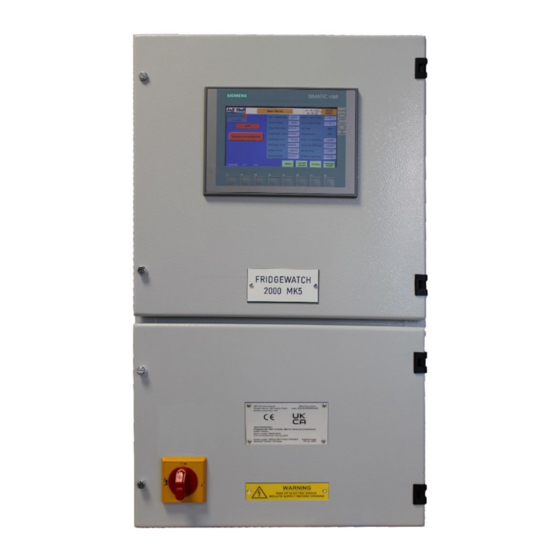
Fridgewatch
2000 Controller Mk5
®
Publication: 3-59
Fridgewatch 2000 Controller Mk5
Issue 3.2 : 05.23
Issue 3.2 : 05.23
Section 3
Advertisement
Table of Contents

Subscribe to Our Youtube Channel
Related Manuals for J&E Hall Fridgewatch 2000


Summary of Contents for J&E Hall Fridgewatch 2000
- Page 1 Publication: 3-59 Fridgewatch 2000 Controller Mk5 Issue 3.2 : 05.23 Installation, Operating and Maintenance Manual Fridgewatch 2000 Controller Mk5 ® This publication is applicable to the following J & E Hall International Compressors and Packages: HallScrew 2000, 2100, 3100, 3200 and 4200 Series Compressors...
- Page 2 Fridgewatch 2000 Controller Mk5 J & E Hall International 2023 © All rights reserved. No part of this publication may be reproduced or transmitted in any form or by any means, electronic or mechanical, including photocopying, recording or by any information storage or retrieval system, without permission in writing from the copyright holder.
- Page 3 Fridgewatch 2000 Controller Mk5 Safety In common with most other forms of mechanical and electrical equipment, there are a number of potential hazards associated with operating and servicing refrigeration plant. In writing this instruction manual, every emphasis has been given to safe methods of working.
- Page 4 Fridgewatch 2000 Controller Mk5 Electrical Electrical wiring, panel earthing and bonding must be sized and installed to such a standard as to meet the requirements of the national or local codes pertaining to the area in which the installation is taking place.
-
Page 5: Table Of Contents
Read Only ........................21 7.2.2. Operator Setting ......................21 7.2.3. Configuration Setting ....................... 21 7.2.4. Access Levels Operator and Configuration ..............21 Mk5 Fridgewatch 2000 HMI ..................23 8.1. User Interface ........................23 8.2. Menu System ......................... 23 8.1. Configuration Settings ......................24 8.2. - Page 6 Fridgewatch 2000 Controller Mk5 11.6. Clean Screen ......................... 42 Requires Configuration Password (Orange) ............... 43 12.1. Hours Run and Number of Starts ................... 43 12.2. Set Time and Date ......................... 44 12.3. ANINs Configuration Pages 1 to 3 ..................45 12.4.
- Page 7 Fridgewatch 2000 Controller Mk5 16.5. Using Fridgewatch to Drive (Switch) Relays ................80 16.5.1. RS 485 Modbus RTU Station Address ................80 16.6. Summary of Primary / Secondary Connections ..............82 16.6.1. Power Supply Connections (Lower Half of Enclosure) ............ 82 16.6.2.
- Page 8 Fig 9 Fridgewatch Configuration Settings Numbers and Timer ............24 Fig 10 Fridgewatch Configuration Settings Number ................25 Fig 11 Fridgewatch Configuration Settings ANIN ................. 25 Fig 12 Mk5 Fridgewatch 2000 HMI ....................... 26 Fig 13 SIMATIC HMI Outdoor Panel ....................27 Fig 14 Menu Page ..........................28 Fig 15 Analogue Ports Page 1 ......................
- Page 9 Fridgewatch 2000 Controller Mk5 Fig 58 DIGIN Wiring Connections to Slot 2 ..................88 Fig 59 DIGIN Wiring Connections to Slot 2 ..................89 Fig 60 DIGOUT Wiring Connections to Slot 1..................90 Fig 61 DIGOUT Wiring Connections to Slot 1..................91 Fig 62 DIGOUT Wiring Connections to Slot 2..................
- Page 10 Fridgewatch 2000 Controller Mk5 List of Tables Table 1 Abbreviations ........................... 13 Table 2 Technical Data ......................... 15 Table 3 Overview of Access Levels and Passwords ................20 Table 4 Under-range Trip Pressures For Different Transmitter Types ..........72 Table 5 Summary of Differential Pressure Sensing ................73 Table 6 All HallScrew Compressors –...
-
Page 11: About This Publication
Fridgewatch 2000 Controller Mk5 About this Publication These instructions have been prepared according to the following standards: • BS EN ISO 11442: Technical product documentation. Document management; • BS EN ISO 12100: Safety of machinery - General principles for design - Risk assessment and risk reduction;... -
Page 12: Care And Protection Of Fridgewatch
Fridgewatch 2000 Controller Mk5 Care and Protection of Fridgewatch CAUTION If welding is to be carried out in the vicinity of the Fridgewatch or any other items of plant containing semi-conductor devices, for example, transistors and microprocessors, the welding equipment must be adequately earthed adjacent to the point of weld. -
Page 13: Personnel Permitted To Install, Commission And Maintain Fridgewatch
Fridgewatch 2000 Controller Mk5 Personnel Permitted to Install, Commission and Maintain Fridgewatch It is essential that only authorised and competent personnel are allowed to install, commission and maintain the Fridgewatch. A permit to work system should be introduced before commissioning begins, and should be rigorously enforced thereafter. -
Page 14: General Description
If a trip occurs, the run signal is removed instantly and independent of microprocessor operation. Safety inputs and all other digital inputs are read into Fridgewatch 2000 in the form of 24 V dc signals. -
Page 15: System Settings
The previous versions used ‘jumpers’ and potentiometers to allow the setup of the Fridgewatch. This Mk5 version of the Fridgewatch 2000 Controller has extra software settings in the menu, which will need to be configured to allow the unit to operate NOTE: Mk5 has 287 settings instead of the 182 the Mk4 had. -
Page 16: Fig 1 Control Internal Layout (Upper)
Fridgewatch 2000 Controller Mk5 Fig 1 Control Internal Layout (Upper) Section 3 Publication 3-59 Issue 3.2 : 05.23 Page 16 of 222... -
Page 17: Fig 2 Control Door Internal Layout (Upper)
Fridgewatch 2000 Controller Mk5 Fig 2 Control Door Internal Layout (Upper) Fig 3 230 V Internal Layout (Lower) Publication 3-59 Section 3 Page 17 of 222 Issue 3.2 : 05.23... -
Page 18: Fig 4 Internal Layout
Fridgewatch 2000 Controller Mk5 Fig 4 Internal Layout Section 3 Publication 3-59 Issue 3.2 : 05.23 Page 18 of 222... -
Page 19: Enclosure Dimensions And Details Of Cable Entries
Fridgewatch 2000 Controller Mk5 Enclosure Dimensions and Details of Cable Entries Gland Plate 420 mm (335 mm x 110 mm) 390 mm 60 mm 141 mm 197 mm 600 mm 720 mm 60 mm 230 mm Length Length Length Length... -
Page 20: Security
Fridgewatch 2000 Controller Mk5 Security Changes to Operating Mode, Control Settings and more especially System Configuration Settings by unauthorised personnel who do not understand the implications of their actions may result in the plant operating outside its maximum performance limits with the potential for damage to equipment and the associated risk of injury to personnel. -
Page 21: Password Access Levels
Fridgewatch 2000 Controller Mk5 7.1. Password Access Levels There are three different access levels: User, Operator and Configuration, the last two levels are accessed via different passwords. The access level is incremental, the Configuration level affords more permissions than the Operator. -
Page 22: Fig 6 Password Logon
Fridgewatch 2000 Controller Mk5 Touch the parameter to be changed. The Logon page is displayed. Touch the Password box to display a Touch Input Panel page for alphanumeric input. Type in the password for the access level required and press the enter button. The Logon page is displayed. -
Page 23: Mk5 Fridgewatch 2000 Hmi
Fridgewatch 2000 Controller Mk5 Mk5 Fridgewatch 2000 HMI 8.1. User Interface Loss of power to Fridgewatch, turning the panel isolator to ‘off’ or in the event of a power failure, will extinguish the display. The programmed settings are not lost, however, as they are backed up in non-volatile memory. -
Page 24: Configuration Settings
Configuration Settings The commissioning engineer initially determines the setting values from the previous Fridgewatch 2000 Controller. Later, after experience has been gained of plant performance, it may be desirable to fine-tune certain values; in some cases, this can be done even while the compressor is running. -
Page 25: Settings Number Setting
Fridgewatch 2000 Controller Mk5 8.4. Settings Number Setting To configure a Control Setting other than a timer. • Yellow Box is an Operator Setting; • Orange Box is a Configuration Setting. Examples shown are S59 and S209. These Yellow/Orange Boxes has a ‘numerical’ number Fig 10 Fridgewatch Configuration Settings Number 8.5. -
Page 26: Push Buttons Functions On The Fridgewatch Hmi
F3 = Current Alarms F5 = Menu Page F7 = BACK F2 = Reset F4 = Alarm History F6 = Not Used F8 = NEXT Fig 12 Mk5 Fridgewatch 2000 HMI Section 3 Publication 3-59 Issue 3.2 : 05.23 Page 26 of 222... -
Page 27: Simatic Hmi Outdoor Panel
Fridgewatch 2000 Controller Mk5 SIMATIC HMI Outdoor Panel There is an HMI for outdoor applications. This HMI is used for demanding applications, under extreme ambient conditions. This makes simple operation and monitoring when used for outdoor applications. Fig 13 SIMATIC HMI Outdoor Panel... -
Page 28: Menu Page
IP Address The IP address is displayed under the software version. 10.3. Home Page Fig 12 Mk5 Fridgewatch 2000 HMI shows the home page for information about this page; refer to 13. Home Page. Section 3 Publication 3-59 Issue 3.2 : 05.23... -
Page 29: Analogue Points Pages 1 To 3
Fridgewatch 2000 Controller Mk5 10.4. Analogue Points Pages 1 to 3 The Analogue Points pages are accessed from the Analogue Points button or via the Menu Page. The analogue points available for display depends on the application, only those analogue inputs and outputs configured to Fridgewatch are displayed. -
Page 30: Digital I/O (Digin/Digout)
Fridgewatch 2000 Controller Mk5 10.5. Digital I/O (DIGIN/DIGOUT) The Digital I/O pages are accessed from the Digital I/O button via the Menu Page. The DIGIN/DIGOUT points available for display depends on the application, only those analogue inputs and outputs configured to Fridgewatch are displayed. -
Page 31: Digital Outputs Pages 1 And 2 (Digout)
Fridgewatch 2000 Controller Mk5 10.5.2. Digital Outputs Pages 1 and 2 (DIGOUT) The Digital Output pages are accessed from the Digital I/O button via the Menu Page. When a DIGOUTs is off the circle to the right of the DIGOUTs description is grey, changing to green when the DIGOUTs is on. -
Page 32: Diagnostics: Page 1 And 2
Fridgewatch 2000 Controller Mk5 10.6. Diagnostics: Page 1 and 2 The Diagnostics pages are accessed from the Diagnostics button via the Menu Page. The diagnostics available for display depends on the application. This page displays all plant diagnostics parameters grouped together for ease of analysis. -
Page 33: P + I Trends
Fridgewatch 2000 Controller Mk5 10.7. P + I Trends The P + I Trends pages are accessed from the P + I Trends button via the Menu Page. This page displays all plant P + I control as a graph. -
Page 34: Current Alarms
Fridgewatch 2000 Controller Mk5 10.8. Current Alarms The Current Alarms page is accessed from the Current Alarms button via the Menu Page. This page displays any Current Alarms. A list of reasons for normal stop, i.e. why the compressor stopped other than a trip event. -
Page 35: System Limits And Information Displays
Fridgewatch 2000 Controller Mk5 10.10. System Limits and Information Displays Access to the System Limits and Information pages are from the Current Alarms page or the Alarm History page. 10.10.1. Limiting The Limiting page is accessed from the Current Alarms page or the Alarm History. -
Page 36: 10.10.2. Information Only
Fridgewatch 2000 Controller Mk5 10.10.2. Information Only The Information Only page is accessed from the Current Alarms page or the Alarm History. This page displays ‘Information Only’ Events. Refer to 20.1. Information Only Events. Fig 27 Information Only Section 3 Publication 3-59 Issue 3.2 : 05.23... -
Page 37: Modbus Registers Pages 1 To 5
Modbus Registers Pages 1 to 5 The Modbus Register pages are accessed from the Modbus Register button via the Menu Page. The Mk5 Fridgewatch 2000 Controller can communicate with external devices over the Fridgewatch Highway. Two communication protocols are supported, the proprietary Fridgewatch protocol or Modbus RTU protocol. -
Page 38: Requires Operator Password (Yellow)
Fridgewatch 2000 Controller Mk5 Requires Operator Password (Yellow) 11.1. Control Settings The Control Settings page is accessed from the Control Settings button via the Menu Page; refer to 15. Principles of Control. Fig 29 Control Settings Section 3 Publication 3-59 Issue 3.2 : 05.23... -
Page 39: Primary / Secondary Settings
Fridgewatch 2000 Controller Mk5 11.2. Primary / Secondary Settings The Primary / Secondary Settings pages are accessed from the Primary / Secondary Settings button via the Menu Page; refer to 15.3. Primary / Secondary Operation. Fig 30 Primary / Secondary Control Settings... -
Page 40: Double Set Point And Days
Fridgewatch 2000 Controller Mk5 11.3. Double Set Point and Days The Double Set Point and Days Settings page is accessed from the Double Set Point and Days Settings button via the Menu Page. The Fridgewatch provides the facility to toggle or slide between two different sets of control values;... -
Page 41: Liquid Injection Settings
Fridgewatch 2000 Controller Mk5 11.4. Liquid Injection Settings The Liquid Injection Settings page is accessed from the Liquid Injection Settings button via the Menu Page. Liquid injection Settings can be viewed at any time, but the value of a setting can only be changed by using the Operator password or higher access level;... -
Page 42: Operating Mode
Fridgewatch 2000 Controller Mk5 11.5. Operating Mode The Operating Mode page is accessed from the Operating Mode button via the Menu Page. This page permits the plant operating mode to be changed. All possible operating modes are illustrated. The operating mode can only be changed by using the Operator password or higher access level refer to: 7. -
Page 43: Requires Configuration Password (Orange)
Fridgewatch 2000 Controller Mk5 Requires Configuration Password (Orange) 12.1. Hours Run and Number of Starts The Hours Run and Number of Starts page is accessed from the Hours Run and Number of Starts button via the Menu Page. The data available for display depends on the application. -
Page 44: Set Time And Date
Fridgewatch 2000 Controller Mk5 12.2. Set Time and Date The Set Time and Date page is accessed from the Set Time and Date button via the Menu Page. This page permits the current time and date to be changed. Time and date can only be changed by using the Operator password or higher access level;... -
Page 45: Anins Configuration Pages 1 To 3
Fridgewatch 2000 Controller Mk5 12.3. ANINs Configuration Pages 1 to 3 The ANINs Configuration pages are accessed from the ANINs Configuration button via the Menu Page. This page permits the ANIN Configuration mode to be changed. All possible ANIN Configurations are illustrated. -
Page 46: System Configuration Pages 1 To 7
Fridgewatch 2000 Controller Mk5 12.4. System Configuration Pages 1 to 7 The System Configuration settings pages are accessed from the System Configuration settings button via the Menu Page. System configuration settings affect the way Fridgewatch interfaces with the refrigeration plant and must be entered during commissioning, before starting the plant for the first time. -
Page 47: Settings S1 To S287 Pages 1 To 38
21. Control Settings, to view or change settings refer to this section. The commissioning engineer, from the previous Fridgewatch 2000 Controller, initially will determine these setting values. Later, after experience has been gained of plant performance, it may be desirable to fine-tune certain values;... -
Page 48: Alt Settings (Alarm, Limit & Trip) Pages 1 To 7
Alarm, limit and trip settings can be viewed at any time, but the value of a setting can only be changed by using a password; refer to 7. Security. The commissioning engineer, from the previous Fridgewatch 2000 Controller, initially will determine these setting values. -
Page 49: Alt (Alarm, Limit & Trip) Timer Settings Pages 1 To 7
Fridgewatch 2000 Controller Mk5 12.7. ALT (Alarm, Limit & Trip) Timer Settings Pages 1 to 7 The Alarm, Limit & Trip Delay Timer Settings Pages are accessed from the ALT Timer Settings button via the Menu Page. Alarm, limit and trip settings can be viewed at any time, but the value of a setting can only be changed by using a password;... -
Page 50: Home Page
Fridgewatch 2000 Controller Mk5 Home Page When the Fridgewatch powers up the Home Page is displayed. The Home Page provides immediate access to the operating status via the key operating parameters displayed on the right-hand side of the page. This button is displayed on all pages. -
Page 51: Menu/Back Button
Fridgewatch 2000 Controller Mk5 13.2. Menu/Back Button Menu Button = Goes to the Menu This button is displayed on all pages. The MENU Page provides immediate access to the operating status via the key operating parameters displayed on the page. -
Page 52: Compressor Status
Fridgewatch 2000 Controller Mk5 13.5. Compressor Status This area of the display depicts the compressor’s current operating status. Off Start/Stop Mode Selected. Examples: In Manual Start/Stop Mode, Waiting for the Button to be Pressed. Waiting for Starts/Hour Timer to Expire. -
Page 53: Load And Unload (Manual Capacity Control Only)
Fridgewatch 2000 Controller Mk5 13.8. Load and Unload (Manual Capacity Control Only) Loads the Compressor Unloads the Compressor These buttons are only displayed on the Home Page when manual capacity control mode is selected. Load Button when Pressed Unload Button... -
Page 54: Communications
Fridgewatch 2000 Controller Mk5 Communications The RS 485 male connector is located under the flap at the bottom of the RS 485 Comms module; refer to Fig 44. Communication between Fridgewatch and another device is made by an RS 485 cable with pin designations as shown in Fig 45. -
Page 55: Rs 485 Port Parameters
Fridgewatch 2000 Controller Mk5 14.1. RS 485 Port Parameters NOTE: No adjustment should be made to these settings. Baud Rate: 9600 Data Bits: Stop Bits: Transmission Mode: Modbus RTU Modbus Secondary address: as set on Fridgewatch RS 485 Modbus RTU Station Address page; refer to setting S61 Modbus Address. -
Page 56: Communications Example
Fridgewatch 2000 Controller Mk5 14.2.1. Communications Example Read Modbus Holding Register 4073 (Register 372 in Absolute Notation, from Fridgewatch set as Modbus Secondary device 01 – and where the only flag set is register 40373 (Discharge Temperature High Alarm Inhibit). -
Page 57: Principles Of Control
Fridgewatch 2000 Controller Mk5 Principles of Control The primary requirement of any refrigeration control system is to match the measured variable (temperature or pressure) as closely as possible to the required control value (set point), while at the same time optimising the use of available compressor capacity. -
Page 58: Slide Valve Position Signal
Fridgewatch 2000 Controller Mk5 15.1.2. Slide Valve Position Signal A Linear Variable Displacement Transducer (LVDT) provides slide valve position for HallScrew series compressors. The LVDT provides the usual 4 to 20 mA signal but is usually provided without any calibration on the LVDT. -
Page 59: Hallscrew 2100 Series And 3100 Old Series Compressors
Fridgewatch 2000 Controller Mk5 15.1.5. HallScrew 2100 Series and 3100 Old Series Compressors The compressor capacity control slide valve modulates capacity between minimum and maximum (25 % and 100 % of full load). Oil pressure, generated by the system suction/discharge pressure... -
Page 60: Proportional Band
Fridgewatch 2000 Controller Mk5 For S1 Set Point Value (temperature/pressure) control, the size of the error determines the amount of corrective action (capacity control slide valve movement/compressor motor speed increase or decrease) taken by Fridgewatch to bring the measured variable to match the set point. -
Page 61: Fig 47 Proportional And Integral (P + I) Control
Fridgewatch 2000 Controller Mk5 Temperature (°C) or Pressure (barg) Current Proportional Band Between Maximum and Minimum – See Table Proportional Band at Maximum Proportional Band Steady State Error Control Error at Minimum Set Point Measured Value Deadband Proportional Band at Minimum... -
Page 62: Integral Action Time
Fridgewatch 2000 Controller Mk5 15.2.2. Integral Action Time By introducing an integral term into the control action, steady state errors can practically be eliminated whilst achieving stable control. Integral control integrates error with respect to time, that is, a small fraction of the error is added to a running total at each control assessment. -
Page 63: Primary / Secondary Operation
15.3. Primary / Secondary Operation The Mk5 Fridgewatch 2000 Controller can be linked with another Mk5 Fridgewatch 2000 Controller and then act as either the Primary or Secondary controller on a common control system. -
Page 64: Starting The Primary Compressor
Secondary compressor capacity, as commanded by the Primary Fridgewatch Controller. Fig 50 Secondary Control Settings The Primary and Secondary Mk5 Fridgewatch 2000 Controllers must be wired via a changeover switch to prevent both controllers being select as Primary at the same time. -
Page 65: Starting And Stopping The Secondary Compressor
Fridgewatch 2000 Controller Mk5 15.3.2. Starting and Stopping the Secondary Compressor Assuming the Primary compressor starts first, when the Primary loads to maximum capacity or limiting prevents the Primary loading further, the Secondary compressor is started. To minimise power consumption it is essential to avoid starting the Secondary compressor until absolutely necessary and not to have it running longer than necessary. -
Page 66: Starting And Stopping The Compressor
The final element in the control system relates to starting and stopping the compressor. Fig 51 Control Settings Where Mk5 Fridgewatch 2000 Controllers are linked together in Primary / Secondary configuration, the first compressor to start would normally be the one controlled by the Primary Mk5 Fridgewatch 2000 Controller; refer to 15.3.1. -
Page 67: Fig 52 Possible Compressor Start/Stop And Capacity Control Modes
Fridgewatch 2000 Controller Mk5 Operating Mode Selection Control Mode: Setting Start/Stop - Compressor Started By Compressor Stopped By Capacity Control Capacity Control No control action. From the Home Page, From the Home Page, From the Home START button pressed. CONTROLLED STOP button... -
Page 68: Control Philosophy For Compressor Operation After A Transmitter Failure
Fridgewatch 2000 Controller Mk5 Additionally, with auto start/stop selected, it is possible to use early start value S15 to define a rate of change required to start the compressor. This facility can be used in circumstances where a sudden load might be applied to the system, and waiting for the start value to be exceeded would introduce an unacceptable delay before the compressor starts. -
Page 69: Capacity Control By Fridgewatch Controller
Fridgewatch 2000 Controller Mk5 The exceptions to this general rule are P2 and P11 (usually System Pressure and Suction Pressure) as they are often subjected to standing pressures above the rating of the fitted transmitter when the plant is not running. -
Page 70: Limiting Inputs
Fridgewatch 2000 Controller Mk5 15.7. Limiting Inputs It may sometimes be necessary to use limiting to restrict the refrigeration capacity of the compressor. The facility prevents system operation outside design parameters or chosen limits and allows the plant to keep running under difficult conditions rather than tripping on a fault. -
Page 71: Current Limiting
Fridgewatch 2000 Controller Mk5 15.7.2. Current Limiting Current limiting, the type of limiting input most commonly used, protects the compressor motor and VSD or switch gear from damage which may occur if the motor tries to exceed the design full load current. -
Page 72: High Pressure Cut-Out Function By Transmitter
Fridgewatch 2000 Controller Mk5 15.9. High Pressure Cut-out Function by Transmitter Using an electro-mechanical cut-out in with Fridgewatch’s special hardware features offers a high speed and reliable HP cut-out function. If required, the Fridgewatch can perform the HP cut-out function in software from discharge pressure measured by a pressure transmitter. -
Page 73: Oil Management Systems
Fridgewatch 2000 Controller Mk5 15.10. Oil Management Systems The Fridgewatch caters for HallScrew compressors with oil management systems with or without an oil pump. • No oil pump, system suction/discharge pressure differential is high enough to maintain oil follow; • Start-up oil pump, runs to lubricate the gland and bearings before the compressor starts, then stops. -
Page 74: Summary Of Differential Pressure Sensing
Fridgewatch 2000 Controller Mk5 15.11. Summary of Differential Pressure Sensing • Settings shown shaded and in bold are mandatory, for example, P58; • Settings marked as ‘Unused’ are ignored when bold settings are as indicated; Settings shown in italics may be adjusted during •... -
Page 75: Table 7 Hs 2000 Series Compressors - Oil Pressure Trips By Transmitters
Fridgewatch 2000 Controller Mk5 Standard Solenoid Valve and Pressure Sensing Configuration Setting Arrangement (S195 Oil Feed Type = 0) Oil Pump/System Type S194 = → ODP1 Starting Delay S52 = → → ODP2 Starting Delay S53 = Unused Unused Start-up Oil Pump Run Time or Demand →... -
Page 76: Table 8 Hs 2100 And Hs 3100 Series Compressors - Oil Pressure Trips By Transmitters
Fridgewatch 2000 Controller Mk5 Standard Solenoid Valve and Pressure Sensing Configuration Setting Arrangement (S195 Oil Feed Type = 0) Oil Pump/System Type S194 = → ODP1 Starting Delay S52 = → → ODP2 Starting Delay S53 = Unused Unused Start-up Oil Pump Run Time or Demand →... -
Page 77: Demand Oil Pump
Fridgewatch 2000 Controller Mk5 Standard Solenoid Valve and Pressure Sensing Configuration Setting Arrangement (S195 Oil Feed Type = 0) Oil Pump/System Type S194 = → ODP1 Starting Delay S52 = → → ODP2 Starting Delay S53 = Unused Unused Start-up Oil Pump Run Time or Demand →... -
Page 78: Oil Filling Pump
Fridgewatch 2000 Controller Mk5 When the pump is running, P24 is determined by pump head and cannot be used to decide if there would be sufficient pressure if the pump is not running. The available upstream pressure that is unaffected by the pump running or not is equal to discharge pressure so that is why P12 is used to decide if the pump can be switched off. -
Page 79: Installation
Fridgewatch 2000 Controller Mk5 Installation Installing the Mk5 Fridgewatch 2000 Controller involves the following steps: • Decide on the controlling parameters, temperature or pressure, from which start, stop and set point values are to be derived; NOTE: The commissioning engineer, from the previous Fridgewatch 2000 Controller, initially will determine these setting values. -
Page 80: Digital Outputs
NOTE: A suggested relay would be an Omron LY2 (RS Components part number 329-799). 16.5.1. RS 485 Modbus RTU Station Address The Mk5 Fridgewatch 2000 Controller supports Modbus RTU communications protocol. If used, enter the number of the Modbus station on the RS 485 Modbus RTU Station Address page. -
Page 81: Fig 53 Transmitter Installation
Fridgewatch 2000 Controller Mk5 Pressure Transducer Connection ¼” BSP to 6 mm Compression Fitting 6 mm Suction Pressure Compression Dowty Gauge Fitting Seal Gauge Valve Pressure 6 mm Wire to Transducer Gauge Line Fridgewatch Framework 6 mm Gauge Line Wire to... -
Page 82: Summary Of Primary / Secondary Connections
Fridgewatch 2000 Controller Mk5 16.6. Summary of Primary / Secondary Connections If Mk5 Fridgewatch 2000 Controllers are to be connected together in Primary / Secondary configuration. Note the following: • Operator setting S19 must be set to 1 on both Primary and Secondary Mk5 Fridgewatch 2000 Controllers;... -
Page 83: Panel Heater
Fridgewatch 2000 Controller Mk5 16.6.2. Panel Heater The outdoor Fridgewatch is fitted with a 30 W self-regulating anti- condensation heater. 16.6.3. Wiring Connections to dc Circuits (Upper Half of Enclosure) The upper half of the Fridgewatch enclosure contains the thermistor and... -
Page 84: Fig 54 Economiser Arrangements: Wiring To Liquid Line Solenoid Valves
Liquid to Condenser Evaporator Typical Multiple Compressor Application With Common Refrigerant Circuit Compressors Individually Controlled by their own Mk5 Fridgewatch 2000 Controller Solenoid Valve Connected to Terminals 285 Solenoid Valve Connected to Terminals 189 (in main liquid line through the economiser) -
Page 85: Terminal Block Wiring Upper
Fridgewatch 2000 Controller Mk5 Terminal Block Wiring Upper Wiring connections are made to terminals in the upper half of the enclosure. Slot 1 24 V dc 3K13-3/B 116A Discharge Pressure I100.0 High Switch Dla 0 Suction Pressure I100.1 Low Switch... -
Page 86: Fig 56 Digin Wiring Connections To Slot 1
Fridgewatch 2000 Controller Mk5 User Trip I100.7 If not fitted, link terminals Dla 7 DTR 3-8/B Discharge Oil HT Thermistor I101.0 Relay (DTR) Dlb 0 Evaporator I101.1 If not fitted, link terminals Flow Switch Dlb 1 Condenser Flow / Diff I101.2... -
Page 87: Fig 57 Digin Wiring Connections To Slot 2
Fridgewatch 2000 Controller Mk5 Slot 2 24 V dc Compressor Running I200.0 Signal Dla 0 A running signal should be returned Oil Pump to Fridgewatch via volt-free contacts Running I200.1 in the starter that close when the oil Signal pump starts and runs. -
Page 88: Fig 58 Digin Wiring Connections To Slot 2
Fridgewatch 2000 Controller Mk5 138A 4K5 4-3/B Load Request I200.5 Signal Dla 5 139A 4K6 4-4/B Unload Request I200.6 Signal Dla 6 Min Load I200.7 Signal Dla 7 50% Load I201.0 Signal Dlb 0 Max Load I201.1 Signal Dlb.1 Fig 58 DIGIN Wiring Connections to Slot 2... -
Page 89: Fig 59 Digin Wiring Connections To Slot 2
Fridgewatch 2000 Controller Mk5 Remote oil fill push-button contacts close to run the oil pump (oil fill), release the button to open the contacts and stop the pump. Oil Filter If required, an oil filter blocked Blocked Signal I201.2 differential pressure switch can be... -
Page 90: Fig 60 Digout Wiring Connections To Slot 1
Fridgewatch 2000 Controller Mk5 0 V dc Slot 1 Compressor start 3K1 3-3/B output relay Compressor Q100.0 Run Request DQa.0 Compressor 5SSR1 Q100.1 Capacity Increase DQa.1 Compressor 5SSR2 Q100.2 Capacity Decrease DQa.2 Oil Injection Q100.3 Solenoid Valve Relay DQa.3 Bypass Solenoid Q100.4... -
Page 91: Fig 61 Digout Wiring Connections To Slot 1
Fridgewatch 2000 Controller Mk5 Oil pump run 24 V dc low consumption relay output relay mounted in the auxiliary starter. Oil Pump Fridgewatch will energise this Q100.7 relay when the oil pump is Request DQa.7 required to run Liquid Valve Q101.0... -
Page 92: Fig 62 Digout Wiring Connections To Slot 2
Fridgewatch 2000 Controller Mk5 0 V dc Slot 2 Condenser / Evaporator Q200.0 Valve DQa.0 Oil Feed Q200.1 Valve DQa.1 Oil Cooler Q200.2 Solenoid Valve DQa.2 Q200.3 Heater DQa.3 Minimum Q200.4 Load Signal DQa.4 Running 6K10 Q200.5 Signal DQa.5 Maximum 6K11 Q200.6... -
Page 93: Fig 63 Digout Wiring Connections To Slot 2
Fridgewatch 2000 Controller Mk5 6K13 Q201.0 DQb.0 Operating Mode 6K14 Q201.1 Confirmed DQb.1 S68 = 0: output 1 on when compressor running with P4 above the switching position, off below or compressor not running. Intermediate S68 = 1: output 1 on when... -
Page 94: Fig 64 Anin And Anout Wiring Connections To Slot 5
Fridgewatch 2000 Controller Mk5 0 V dc 24 V dc ANIN 0 Measured Pressure 4 to 20 mA (P2) Slide Valve Position ANIN 1 (SVP) or Motor Speed: 4 to 20 mA Required 4 to 20 mA (P4) Motor Current/... -
Page 95: Fig 65 Anin And Anout Wiring Connections
Fridgewatch 2000 Controller Mk5 0 V dc 24 V dc Oil Injection ANIN 7 Pressure 4 to 20 mA (after filter) (P13) ANIN 8 Oil Injection Pressure 4 to 20 mA (before filter) (P14) Evaporator ANIN 9 Cooled 4 to 20 mA... -
Page 96: Fig 66 Wiring Connections To External Devices
Fridgewatch 2000 Controller Mk5 0 V dc 24 V dc HP cut-out High Relay contacts shown in healthy Pressure condition. Switch Signal 24 V dc Oil Separator If not fitted, Opto sensor in link terminals 119 and 120 Opto Sensor... -
Page 97: Fig 67 Wiring Connections To External Devices
Fridgewatch 2000 Controller Mk5 0 V dc 24 V dc Run Enable Link terminals 135 and 136 If relays are driven via an external controller. No link required for J and E Hall Load systems and auto controller applications Unload... -
Page 98: Fig 68 Wiring Connections Pt 100 And Motor Current
20 Ω to 50 Ω (20R to 50R) shunt resistor across Signal From 20 to 4 to 20 mA Fridgewatch 2000 input and set S64 = -1 x motor line Soft-Starter 50 Ω Signal current (not phase current) corresponding to the 20 mA or Inverter signal. -
Page 99: Fig 69 Wiring Connections Input / Output
Fridgewatch 2000 Controller Mk5 Function Terminals Remarks To Fridgewatch Auto Controller or System Digital Outputs to Fridgewatch Auto Controller or Controller System Controller: S19 = 0 +24 V dc Common reference voltage. Minimum load signal Compressor at minimum load. Compressor running. -
Page 100: Fig 70 Wiring Connections Input / Output
Required = 1, becomes a run enable signal (contacts Load request contacts closed) permits Fridgewatch to start in auto start/stop mode. Unload request or From Another Mk5 Fridgewatch 2000 Digital Inputs From a Primary Mk5 Fridgewatch Controller in Primary / Secondary 2000 Controller: S19 = 1 Configuration Link Link terminals 135 and 136. -
Page 101: Fig 71 Wiring Connections Input / Output
+24 V supply to drive relays. Operating mode 0 V. confirmation relay or To Another Mk5 Fridgewatch 2000 Digital Outputs to Another Mk5 Fridgewatch 2000 Controller in Primary / Secondary Controller in Primary / Secondary Configuration: Configuration S19 = 1 Common Common. -
Page 102: Terminal Block Wiring Lower
Fridgewatch 2000 Controller Mk5 Terminal Block Wiring Lower Wiring connections are made to terminals in the lower half of the enclosure. Function Terminals Remarks Load Valve Load valve output, used on certain VSD applications, can be used to drive load valve on VSD applications. -
Page 103: Fig 73 Wiring Connections Relay Outputs Lower Half Of Panel Continued
Fridgewatch 2000 Controller Mk5 Function Terminals Remarks Energise (open) when the compressor starts, Liquid Line de-energise (close) when the compressor stops. Solenoid Valve If the system is designed to pump-down on stopping, the 230/110 V ac liquid line solenoid valve de-energises (closes) when the pump-down sequence begins. -
Page 104: Fig 74 Wiring Connections For Primary / Secondary Without External Run Request Or Run Enable Signal
Fridgewatch 2000 Controller Mk5 Mk5 Fridgewatch Mk5 Fridgewatch 2000 Compressor A 2000 Compressor B Compressor B Primary/Compressor A Secondary 1 Pair 0.5 mm Screened Cable 1 Pair 0.5 mm Screened Cable Ethernet cable The cable connects between the Fridgewatch CPU modules... -
Page 105: Commissioning
These commissioning instructions assume the operator has read and fully understood how the user interface functions. Leave commissioning the Fridgewatch 2000 Controller until, all refrigerant, condenser cooling water, evaporator cooled medium and electrical connections have been made, and everything is otherwise ready for starting the plant for the first time. -
Page 106: Authority To Use Passwords
Fridgewatch 2000 Controller Mk5 19.2.1. Authority to Use Passwords Changes to the Operating Mode and Settings and cannot come into effect without using the appropriate password, so the authority to make changes can be confined to designated password holders; refer to 7. -
Page 107: Transmitter Calibration
Fridgewatch 2000 Controller Mk5 19.3.1. Transmitter Calibration Temperature and pressure transmitters can be some distance from the panel, this cable length will need to be included in the panel’s calibration to insure the circuit is to be matched to accurately to the transmitter. -
Page 108: Temperature Transmitter Calibration
Fridgewatch 2000 Controller Mk5 If, after scaling the readings, the required accuracy cannot be achieved then the transmitter or interconnecting wiring is probably defective. Record calibration details in Appendix 5 Settings Record. 19.3.3. Temperature Transmitter Calibration The following equipment is required: •... -
Page 109: Compressor Slide Valve Position Lvdt Calibration
Initially, control settings will depict their default values as defined in Appendix 5 Settings Record. The commissioning engineer, from the previous Fridgewatch 2000 Controller, initially will determine these setting values. Later, after experience has been gained of plant performance, it may be desirable to fine-tune certain values;... -
Page 110: Changing System Configuration Settings After Commissioning
– ‘manual’ capacity control mode; refer to 19.5. Operating Mode for the First Start. If the Mk5 Fridgewatch 2000 Controller is not to be run in Primary / Secondary configuration but is subject to a central controller, for example,... -
Page 111: Fig 78 Changing The Operating Mode
Fridgewatch 2000 Controller Mk5 From the Menu Page, press the OPERATING MODE button to display the Operating Mode Selection page. Touch the current operating mode to display the Touch Input Panel (enter Operator password or higher, refer to 7. Security). All possible operating modes are displayed with the current mode. -
Page 112: Event Codes
Fridgewatch 2000 Controller Mk5 Event Codes Certain operating conditions, including fault conditions which trip and stop the compressor, are detected by the Fridgewatch and displayed as an event code. There are different event codes, E1 to E107, although some are not applicable to a particular application. -
Page 113: Transmitter Out Of Range
Event Codes Description This part of the manual provides a full description of each event code which may appear on the Mk5 Fridgewatch 2000 Controller. A quick-reference of all event codes may be found in Appendix 3 Event Codes E1/E107 Quick-Reference. - Page 114 Fridgewatch 2000 Controller Mk5 E2 - Discharge / Oil Temperature DIGIN Switch High - Trip, Compressor Healthy Off, Manual Reset This event code is implemented for all applications, which use a discharge high temperature thermistor and/or oil high temperature thermistor, terminals 162/163 (DIGIN I101.0).
- Page 115 Fridgewatch 2000 Controller Mk5 E6 - HP DIGIN Switch High - Trip, Compressor Healthy Off, Manual Reset This event code is implemented for all applications, terminals 115/116 (DIGIN I100.0). Cause: The pressure of the refrigerant vapour in the discharge line has exceeded the HP cut-out setting.
- Page 116 Fridgewatch 2000 Controller Mk5 E10 - Not Used E11 - DIGIN Switch - Start Inhibit, Not a Trip, Self-clearing This event code is only implemented if a start inhibit signal is supplied using DIGIN I101.4 on terminals 133/134; refer to Fig 56.
- Page 117 Fridgewatch 2000 Controller Mk5 E15 - Suction Pressure (P11) Low - Trip, Compressor Healthy Off, Manual Reset This event code is implemented if P11 is enabled. Cause: The temperature measured by point P11 is below the value entered in setting S159.
- Page 118 Fridgewatch 2000 Controller Mk5 E19 - Oil Filter Differential Pressure High - Alarm, Auto Reset E19 - Oil Filter Blocked DIGIN Switch - Alarm, Manual Reset This event code is implemented if a differential pressure switch is connected across terminals 229/230 (refer to Fig 47), or if S131 is configured to calculate oil filter pressure drop (P28) and an alarm value has been set in configuration setting S168 and S275.
- Page 119 Fridgewatch 2000 Controller Mk5 E22 - Evaporator Circulation - Info Only, Not a Trip, Self-clearing This event code is implemented for applications where Fridgewatch controls the evaporator pump, i.e. the pump start relays are connected to terminals 223/224 (DIGOUT Q100.6) and +24/225 (DIGIN I200.3) (refer to Fig 60) and Configuration Setting S57 = 2 or 3.
- Page 120 Fridgewatch 2000 Controller Mk5 E26 - Evaporator Flow - Trip, Compressor Healthy Off, Manual Reset This event code is intended to be used for applications where a flow switch or other contacts is connected to terminals 213/214 (DIGIN I101.1); refer to Fig 56.
- Page 121 Fridgewatch 2000 Controller Mk5 E30 - Auxiliaries Pump Failed to Start -Trip, Compressor Healthy Off, Manual Reset This event code is implemented for all applications. Cause: When Fridgewatch sends a start signal to the auxiliaries/condenser pump starter, a running signal must be returned to Fridgewatch within the limit set by S50 Auxiliaries (or Evaporator Pump) Start Time.
- Page 122 Fridgewatch 2000 Controller Mk5 E34 - Auxiliaries Pump Failed while Running - Trip, Compressor Healthy Off, Manual Reset This event code is implemented for all applications. Cause: The auxiliaries/condenser pump provides Fridgewatch with a running signal to indicate that it is operating.
- Page 123 Fridgewatch 2000 Controller Mk5 E38 - Discharge Temperature (P16) - Out Of Range, Compressor Healthy Off, Manual Reset This event code is implemented when a signal out of the setting range is given to P16. Cause: Failure of the transmitter, supply fuse blown or faulty field wiring.
- Page 124 Fridgewatch 2000 Controller Mk5 Check the: • Calibration of the input; • Calibration and operation of the transmitter and its range; • Power supply to the transmitter; • Field wiring connections. E43 - Not Used E44 - Not Used E45 - Not Used...
- Page 125 Fridgewatch 2000 Controller Mk5 E53 - Oil Feed Pressure (P23) - Out Of Range, Compressor Healthy Off, Manual Reset This event code is implemented when a signal <1.185mA and >22.81 mA signal is given to P23. Cause: Failure of the transmitter, supply fuse blown or faulty field wiring.
- Page 126 Fridgewatch 2000 Controller Mk5 E57 - Oil Injection Pressure Before Filter (P14) - Out Of Range, Compressor Healthy Off, Manual Reset This event code is implemented when a signal <1.185mA and >22.81 mA signal is given to P14. Cause: Failure of the transmitter, supply fuse blown or faulty field wiring.
- Page 127 Fridgewatch 2000 Controller Mk5 E61 - Suction Temperature (P15) - Out Of Range, Compressor Healthy Off, Manual Reset This event code is implemented when a signal out of the setting range is given to P15. Cause: Failure of the transmitter, supply fuse blown or faulty field wiring.
- Page 128 Fridgewatch 2000 Controller Mk5 E67 - Measured Pressure (P2) High - Alarm This event code is implemented if P2 is enabled. Cause: The pressure measured by point P2 is above the value entered in setting S244 and timer S261 has expired.
- Page 129 Fridgewatch 2000 Controller Mk5 E71 - Measured Temperature (P1) Low - Alarm This event code is implemented if P1 is enabled. Cause: The temperature measured by point P1 is below the value entered in setting S245 and timer S264 has expired.
- Page 130 Fridgewatch 2000 Controller Mk5 E75 - Evaporator Outlet Temperature (P19) Low - Alarm This event code is implemented if P19 is enabled. Cause: The temperature measured by point P19 is below the value entered in setting S237 and timer S266 has expired.
- Page 131 Fridgewatch 2000 Controller Mk5 E79 - Oil Injection Diff Press Running (ODP1) Low - Alarm This event code is implemented if S149 ≠ 0. Cause: The pressure measured is below the value entered in setting; refer to 15.10. Oil Management Systems.
- Page 132 Fridgewatch 2000 Controller Mk5 E86 - Suction Pressure (P11) Low - Load Inhibit This event code is implemented if P11 is enabled. Cause: The temperature measured by point P11 is below the value entered in setting S157. Check the: • Calibration of the input;...
- Page 133 Fridgewatch 2000 Controller Mk5 E90 - DIGIN Switch - Load Inhibit, Compressor Healthy Off, Manual Reset This event code is only implemented if a start inhibit signal is supplied using DIGIN I101.4 on terminals 133/134; refer to Fig 56. Cause: Loading of the compressor is prevented by an external device connected to Fridgewatch terminals 133/134 (DIGIN I101.4).
- Page 134 Fridgewatch 2000 Controller Mk5 E95 - User Analogue (P6) High - Load Inhibit This event code is implemented if P6 is enabled. Cause: The temperature measured by point P6 is above the value entered in setting S253. Check the: • Calibration of the input;...
- Page 135 Fridgewatch 2000 Controller Mk5 E99 - Discharge Pressure (P12) High - Force Unload This event code is implemented if P12 is enabled. Cause: The temperature measured by point P12 is above the value entered in setting S162. Check the: • Calibration of the input;...
- Page 136 Fridgewatch 2000 Controller Mk5 E103 - Measured Temperature (P1) Low - Force Unload This event code is implemented if P1 is enabled. Cause: The temperature measured by point P1 is below the value entered in setting S91. Check the: • Calibration of the input;...
-
Page 137: Control Settings
Control Settings Settings, configurable by the password holder or commissioning engineer, enable the Mk5 Fridgewatch 2000 Controller to provide suitable control, regardless of the type of refrigeration plant to which it is applied. Settings are backed up in non-volatile memory. -
Page 138: Compressor Settings
Fridgewatch 2000 Controller Mk5 21.1. Compressor Settings Fig 79 Control Settings Set Point Value (units: pressure in barg or temperature in °C) This is the temperature or pressure value, depending on the chosen control parameter, which Fridgewatch will attempt to control to when auto capacity control mode is selected. - Page 139 Fridgewatch 2000 Controller Mk5 Stop-to-start timer (units: minute) This is the time, in minutes, that must elapse after the compressor stops before it is allowed to restart. Even if S49 Starts Per Hour timer will permit a restart, the compressor cannot run until S4 has expired.
-
Page 140: Table 12 Run Enable Required In Different Operating Modes - Values For S14
Table 12. Removing the run enable signal stops the compressor and prevents restarting until the signal is restored. Mk5 Fridgewatch 2000 Controller Operating Mode Remote Load and (Off mode not applicable) Unload Digital Inputs... - Page 141 Early start value (units: rate of change of pressure in bar/min or temperature in °C/min) If this option is used, Fridgewatch 2000 starts the compressor before the normal start measured value is reached if the measured value is rising faster than the chosen value.
-
Page 142: Table 13 Evaporator Pump Running Status When Compressor Is Stopped
Table 13 where the pump is indicated as stopped. Two Mk5 Fridgewatch 2000 Controllers operating in Primary / Secondary configuration, with a single evaporator cooled medium pump, will assume that the Primary Fridgewatch will start and run the evaporator pump; as per full flow parallel systems. -
Page 143: Table 14 Operating Mode Indication Using Setting S19
If this Fridgewatch is connected in a Primary / Secondary configuration with another Mk5 Fridgewatch 2000, S19 for both Mk5 Fridgewatch 2000 Controllers must be set to 1. If this Fridgewatch is not connected in Primary / Secondary configuration, S19 can be configured to provide a digital output on terminal 147 to confirm that the correct operating mode is selected. - Page 144 Fridgewatch 2000 Controller Mk5 Two start value/set point/stop value sets required The Fridgewatch provides the facility to toggle or slide between two different sets of control values: No 1 start value, No 1 set point and No 1 stop value, and No 2 start value, No 2 set point and No 2 stop value.
- Page 145 Fridgewatch 2000 Controller Mk5 Either P1 or P2 can be used for automatic set point control (refer to S46 description). Whichever point is chosen applies to both the No 1 and No 2 set points; refer to Table 11. S22 is only used when two different start value/set point/stop value sets are required (S20 >...
-
Page 146: Fig 80 Flowchart To Assist In Adjusting Start Value/Set Point/Stop Value Times
Fridgewatch 2000 Controller Mk5 Number of One Value Set Set S20 = 0 (default) START value sets A change to S1, S2 or S3 changes corresponding S21, S23 or S25. Two Value Sets A change to S21, S23 or S25 changes corresponding S1, S2 or S3. - Page 147 Fridgewatch 2000 Controller Mk5 Use No 2 start value/set point/stop value set Monday to Friday Set to 1 if No 2 start value/set point/stop value set is to be used sometime during the day on Monday to Friday inclusive. Use the default value of 0 if only No 1 start value/set point/ stop value set is to be used on Monday to Friday inclusive, or if the changeover between No 1 and No 2 sets is switched externally through DIGIN 3.
-
Page 148: Table 15 Reason For Last Normal Compressor Stop - Values For S38
Fridgewatch 2000 Controller Mk5 S38 Value Remarks No normal stop since last cleared or powered up. Setting S16 Compressor Availability was set to 0 = unavailable, while the compressor was in the start-up sequence. The Controlled STOP (ALL MODES) button was pressed while the compressor was running. -
Page 149: Table 16 Reason For Current Trip (Event) - Values For S39
Fridgewatch 2000 Controller Mk5 Remarks E1 - Motor Temperature High Switch Trip E2 - High Discharge/Oil Temp Switch Trip E3 - Oil Diff Press Low Trip - ODP2 E4 - Oil Separator Level Switch Trip E5 - LP Switch Trip... -
Page 150: Table 17 Reason For Compressor Not Starting - Values 0 To 10 For S40
Fridgewatch 2000 Controller Mk5 Compressor Prevented From Operator Action (If Required) Compressor Starting By: To Restart Compressor Restarted By: No reason or checking in progress. Fridgewatch reverts to the operating mode The compressor was stopped by it was in before the interruption. -
Page 151: Table 18 Reason For Compressor Not Starting - Values 11 To 20 For S40
Fridgewatch 2000 Controller Mk5 Compressor Prevented From Operator Action (If Required) Compressor Starting By: To Restart Compressor Restarted By: Normal operation, no operator Compressor available to run when the intervention required. Start inhibit signal is On. start inhibit signal is removed. -
Page 152: Fig 81 Starts Per Hour
The range of S42 is from 1 to 99, once is changed, it cannot be reset to 0 again. If S42 = 0, when power is first supplied to the Fridgewatch 2000 Controller, the display shows System Unconfigured, Restart system and enter Configuration Mode, the panel is locked and none of the input buttons will operate. - Page 153 Fridgewatch 2000 Controller Mk5 Auxiliaries (or Evaporator Pump) Start Time (units: second) Typical auxiliaries are the condenser cooling water pump or evaporator cooled medium pump. S50 is the time in seconds allowed for any auxiliaries to start and provide a running signal to Fridgewatch.
- Page 154 Fridgewatch 2000 Controller Mk5 Set hours run on compressor (units: hours run) Should it be necessary to replace the systems compressor, it will be necessary to re-enter the hours run by the compressor. The number displayed is the number of hours run; for example, for 1200 hours, 1200 would be entered and displayed.
- Page 155 Fridgewatch 2000 Controller Mk5 Start-up load position (units: % load) When the compressor starts this is the load position, which the slide valves are moved to establish sufficient suction/discharge pressure differential for satisfactory oil flow. When the slide valves reach this position they are held there until normal capacity control takes over.
-
Page 156: Fig 82 Example Of Using Intermediate Load Output 1
Fridgewatch 2000 Controller Mk5 Motor current high: load inhibit (units: Amp) Transmitter wired to P5 (ANIN 2), used to sense compressor motor current. Provision is made for inputs from an external current limiting device. Motor current high: force unload (units: Amp) - Page 157 Fridgewatch 2000 Controller Mk5 Intermediate load output 2: level (units: % of full load) This output is on terminal 243; refer to Fig 69 and Fig 70. S69 determines the slide valve position at which this output switches. On increasing load the output switches when P4, slide valve position %, rises above the value of S69.
-
Page 158: Fig 83 Set Date And Time
Fridgewatch 2000 Controller Mk5 Oil Separator level nuisance trip delay (units: second) The nuisance trip delay is designed to prevent momentary opening of safety trip contacts from stopping the plant. For example, a sudden temporary fluctuation in the oil separator/reservoir oil level might expose the opto-electronic liquid sensor for a brief period. - Page 159 Fridgewatch 2000 Controller Mk5 Not Used Not Used Not Used Not Used Not Used Not Used Not Used Not Used Measured temperature low: load inhibit (units: °C) S90 defines the measured temperature limit below which compressor loading is inhibited. Measured temperature low: force unload (units: °C) S91 defines the limit below which Fridgewatch sends continuous unload pulses until measured temperature rises above the S91 limit.
- Page 160 Fridgewatch 2000 Controller Mk5 Not Used Not Used Not Used S100 Not Used S101 Not Used S102 Not Used S103 Not Used S104 Not Used S105 Not Used S106 Not Used S107 Not Used S108 Not Used S109 Not Used...
-
Page 161: Table 20 Values For P28 Oil Filter Pressure Drop
Fridgewatch 2000 Controller Mk5 S131 P28 oil filter pressure drop: unused/defined If oil pressure before and after the oil filter is available, by setting S131 to non-zero Fridgewatch will calculate the oil pressure drop across the filter and display this value as P28. - Page 162 Fridgewatch 2000 Controller Mk5 S133 P30 suction superheat: unused/defined If suction temperature (P15) is available and a value for suction gauge is available, then by setting S133 to non-zero Fridgewatch will calculate the suction superheat. Suction gauge pressure may be either P7 if the ANIN 0 monitors suction pressure, or P29 if the ANIN 5 monitors suction pressure.
-
Page 163: Table 21 Values For S147 Oil Feed Differential Pressure (Odp2) Sensing Defined
Fridgewatch 2000 Controller Mk5 S143 Use P19 or P1 for evaporator cooled medium outlet temperature in duty calculation Either P1 or P19 may be defined as the evaporator cooled medium outlet temperature to be used for duty calculations. S143 = 0: use P19 for evaporator outlet temperature. -
Page 164: Table 22 Values For S149 Oil Injection Differential Pressure (Odp1) Sensing Defined
Fridgewatch 2000 Controller Mk5 S148 Oil differential pressure at start-up (ODP2) low trip (units: bar) S148 is the low oil feed differential pressure ODP2 at which Fridgewatch stops the compressor and displays a trip: event code E3 - Oil Differential Pressure at Start-up (ODP2) Low - Trip. - Page 165 Fridgewatch 2000 Controller Mk5 S150 Oil differential pressure during running (ODP1) nuisance trip delay time (units: second) Oil differential pressure during running (ODP1) nuisance trip delay time S50 is designed to prevent a sudden temporary decrease in oil differential pressure from opening safety trip contacts and stopping the plant.
- Page 166 Fridgewatch 2000 Controller Mk5 S161 Discharge pressure high: load inhibit (units: barg) S161 defines the discharge pressure limit above which compressor loading is inhibited. NOTE: The value assigned to S161 Load Inhibit must normally be < than S162 Force Unload.
-
Page 167: Table 23 Automatic Scaling Of P34 Energy Consumption Counter
Fridgewatch 2000 Controller Mk5 S169 P34 (energy consumption counter): unused/used (units: kWh) To enable this feature (sometimes referred to as a kWh meter) a power transmitter must be fitted to P22 and S169 must be set to unity (i.e. S169 = 1). - Page 168 Fridgewatch 2000 Controller Mk5 S171 Pump-down on stopping or on starting and stopping If pump-down is implemented, S171 defines whether pump-down occurs only when the plant stops, or on starting and stopping; refer to 15.8. Pump-down S171 = 0: pump-down occurs only on stopping.
- Page 169 Fridgewatch 2000 Controller Mk5 S176 Run enable signal always required Operator setting S14 can be used to specify the operating mode that is subject to a run enable signal via terminals 137/140. Although S14 cannot be altered without using the Configuration...
-
Page 170: Table 24 Refrigerant Type - Values For S184
Fridgewatch 2000 Controller Mk5 S182 P4 value for minimum load (units: %) If the compressor is fitted with an LVDT providing a 4 to 20 mA input signal to P4 for slide valve position (SVP) or compressor pumping capacity is modulated via a variable speed drive providing a 4 to 20 mA input signal to P4 for slide for motor speed, S63 is set to 3 or 4, 7 or 8. - Page 171 Fridgewatch 2000 Controller Mk5 S185 Slide valve position/motor speed: error delay time (units: second) If SVP fails to reach the required value before S185 times out, Fridgewatch displays an alarm E65 - Slide Valve Position (SVP) / Motor Speed Error (P4) - Alarm.
-
Page 172: Fig 84 Slide Valve Position (Svp)/Motor Speed: Error Tolerance - Values For S18
Fridgewatch 2000 Controller Mk5 Slide Valve Position S18 Slide Valve Position: Error Fixed 1 % error Required Tolerance (value band either side = 2 % for of S18 Example 1) Slide Valve Position Compressor Motor Speed S18 Motor Speed: Error... - Page 173 Fridgewatch 2000 Controller Mk5 S188 Type of Liquid Injection Valve With S187 = 1, liquid injection control required, S188 defines the liquid injection control valve type. S188 = 0: none. S188 = 1: pulsing, for example Danfoss AKV and AKVA.
-
Page 174: Fig 85 Possible Compressor Start/Stop And Capacity Control Modes
Fridgewatch 2000 Controller Mk5 S200 Operating Mode Selection S200 Operating Mode Selection Control Mode: Setting Start/Stop - Compressor Started By Compressor Stopped By Capacity Control Capacity Control No control action. From the Home Page, From the Home Page, From the Home Page, START button pressed. - Page 175 Fridgewatch 2000 Controller Mk5 S201 Not Used S202 Not Used S203 Not Used S204 Not Used S205 Not Used S206 Not Used S207 Delay After Secondary Step Change - Loading & Unloading (units: second) Each time a step change is made to a Secondary compressor (start, step load or step unload) this timer is started.
-
Page 176: Fig 86 Liquid Injection Settings
Fridgewatch 2000 Controller Mk5 Fig 86 Liquid Injection Settings S220 Discharge Temperature (P16) Set Point (units: °C) The measured temperature is sensed at the compressor discharge outlet by P16 (ANIN 18). This is the discharge temperature value which the Fridgewatch P + I control algorithm attempts to control to by opening and closing the electronic liquid injection valve. -
Page 177: Fig 87 Cycle Time
Fridgewatch 2000 Controller Mk5 Conversely, a very large value may produce long periods of running with an error, due to the slow response of the integral action. Setting the integral action time to zero has the effect of switching off the integral action. - Page 178 Fridgewatch 2000 Controller Mk5 S227 Sample time Liquid Injection This is the time interval at which the control response is re-assessed. Beware of entering too small a value in the desire to improve response, as this could lead to instability in the overall control of the economiser electronic expansion valve.
- Page 179 Fridgewatch 2000 Controller Mk5 S237 Evaporator outlet temperature low alarm (units: °C) P19 Transmitter wired to ANIN 21, used to sense evaporator cooled medium outlet temperature. If evaporator outlet temperature falls to the S237 alarm value, time delay S266 is initiated.
- Page 180 Fridgewatch 2000 Controller Mk5 S244 Measured pressure high: alarm (units: barg) If measured pressure rises to the S244 alarm value, time delay S261 is initiated. Fridgewatch displays E67 - Measured Pressure (P2) High - Alarm, if measured pressure is above the S244 value when S261 times out. S244 would normally be set above the S243 force unload pressure value.
- Page 181 Fridgewatch 2000 Controller Mk5 S252 User Analogue (P6) low: load inhibit (units: °C or bar) S251 defines the limit below which Fridgewatch sends continuous unload pulses until User Analogue rises above the S251 limit. These limits override the output from the P + I algorithm or external load/unload signals.
- Page 182 Fridgewatch 2000 Controller Mk5 S260 Discharge temperature high alarm delay time (units second) P16 Transmitter wired to ANIN 18, used to sense discharge temperature. If discharge temperature rises to the S236 alarm value, time delay S260 is initiated. Fridgewatch displays E73 - Discharge Temperature (P16) High - Alarm, if discharge temperature is above the S236 value when S260 times out.
- Page 183 Fridgewatch 2000 Controller Mk5 Fridgewatch displays E77 - Evaporator Inlet Temperature (P20) Low - Alarm. S269 Evaporator Diff Press Nuisance Trip Delay Time Evaporator differential pressure nuisance trip delay Time S269 is designed to prevent a sudden temporary decrease in differential pressure from opening safety trip contacts and stopping the plant.
- Page 184 Fridgewatch 2000 Controller Mk5 S273 Oil differential pressure during running (ODP1) delay time (units: second) S273 is the time in seconds allowed for the oil pressure differential to rise sufficient to establish oil flow and an oil differential pressure in excess of the S154 trip value.
-
Page 185: System Settings
Fridgewatch 2000 Controller Mk5 S282 Evaporator Pump Number of Starts Should it be necessary to replace the systems Evaporator Pump, it will be necessary to re-enter the number of starts by the Evaporator Pump. S283 Auxiliaries Number of Starts Should it be necessary to replace the systems Auxiliaries, it will be necessary to re-enter the number of starts by the Auxiliaries. -
Page 186: Evaporator Cooled Medium Outlet Temperature Low P19
Fridgewatch 2000 Controller Mk5 22.1.2. Evaporator Cooled Medium Outlet Temperature Low P19 Transmitter wired to P19 ANIN 21, used to sense evaporator cooled medium outlet temperature. S165 Evaporator outlet temperature low: load inhibit (units: °C) S166 Evaporator outlet temperature low: force unload (units: °C) S167 Evaporator outlet temperature low trip (units: °C) -
Page 187: Oil Differential Pressure (Odp 1) Low During Running
Fridgewatch 2000 Controller Mk5 22.1.3. Oil Differential Pressure (ODP 1) Low During Running S150 Oil differential pressure during running (ODP1) nuisance trip delay time (units: second) S153 Oil differential pressure during running (ODP1) low trip (units: bar) S154 ODP1: Running Low – Differential (Also, On Demand Oil... -
Page 188: Discharge Pressure P12 Or Temperature P16
Fridgewatch 2000 Controller Mk5 22.2. Discharge Pressure P12 or Temperature P16 22.2.1. Discharge Pressure High P12 Transmitter wired to P12 (ANIN 6), used to sense discharge pressure. S161 Discharge pressure high: load inhibit (units: barg) S162 Discharge pressure high: force unload (units: barg) -
Page 189: Suction Pressure P11
Fridgewatch 2000 Controller Mk5 22.3. Suction Pressure P11 22.3.1. Suction Pressure Low Transmitter wired to P11 (ANIN 5), used to sense suction pressure. S157 Suction pressure low: load inhibit (units: barg) S158 Suction pressure low: force unload (units: barg) S159... -
Page 190: User Analogue Pressure Or Temperature P6
Fridgewatch 2000 Controller Mk5 22.4. User Analogue Pressure or Temperature P6 22.4.1. User Analogue (P6) Low P6 Transmitter wired to P6 ANIN 3, used to sense user analogue. S249 User Analogue (P6) low trip (units: °C or bar) S250 User Analogue (P6) low alarm (units: °C or bar) S251 User Analogue (P6) low: force unload (units: °C or bar) -
Page 191: Measured Pressure P2
Fridgewatch 2000 Controller Mk5 22.5. Measured Pressure P2 22.5.1. Measured Pressure Low Transmitter wired to P2 (ANIN 0), used to sense measured pressure. Measured pressure low: load inhibit (units: barg) Measured pressure low: force unload (units: barg) Measured pressure low trip (units: barg) -
Page 192: Measured Temperature P1
Fridgewatch 2000 Controller Mk5 22.6. Measured Temperature P1 22.6.1. Measured Temperature Low Transmitter wired to P1 ANIN 16, used to sense measured temperature. Measured temperature low: load inhibit (units: °C) Measured temperature low: force unload (units: °C) Measured temperature low trip (units: °C) S245 Measured temperature low alarm (units: °C) -
Page 193: Maintenance
Fridgewatch 2000 Controller Mk5 Maintenance Under normal operating conditions with the Fridgewatch operating correctly, minimum servicing is required or recommended. The following general checks are recommended once a year. • Check measured point values against pressure gauges, thermometers and current meter readings;... -
Page 194: Spares
Fridgewatch 2000 Controller Mk5 Spares Obtain spare parts from the address below: J & E Hall International Telephone: +44 (0) 1332-253400 Hansard Gate, Fax: +44 (0) 1332-371061 West Meadows, Email: spares@jehall.co.uk Derby, Website: www.jehall.com DE21 6JN England 24.1. Fuses Fuse Number... -
Page 195: Appendix 1 Residual Risk Register
Fridgewatch 2000 Controller Mk5 Appendix 1 Residual Risk Register Residual Suggestions to Remove, Hazard and Responsibility Comments Reduce or Control Risk Risks The risks due to electrical static and lightning shall be controlled and minimised by the end-user following Earthing, Lightning protection, international / local codes. - Page 196 The end-user shall ensure that an emergency stop Cat 0 is used and wired to the compressor starter independently of the Fridgewatch 2000 Mk5 controller. Functional This manual of the product Refer to EN-378 for...
-
Page 197: Appendix 2 Measured Points P1/P34 Quick-Reference
Fridgewatch 2000 Controller Mk5 Appendix 2 Measured Points P1/P34 Quick-Reference Possible Application Point ANIN Description Units ANIN 16 Temperature °C ANIN 0 Pressure barg Hours run hour ANIN 1 Slide valve position / Motor Speed ANIN 2 Motor current ANIN 3 User Analogue barg or °C... - Page 198 Fridgewatch 2000 Controller Mk5 Wiring Connections Point Function Associated Settings ANIN Terminals Read/display ANINs Configuration Page 3 Define P1 as the Set Point and/or S46 to S48 inclusive Start Value and/or Stop Value S1 to S3 inclusive, S20 to S26 inclusive,...
- Page 199 Fridgewatch 2000 Controller Mk5 Wiring Connections Point Function Associated Settings ANIN Terminals Read/display ANINs Configuration Page 1 Scale S157 to S159 inclusive, S171 and Pump-down/limiting/trip on P11 (E15) S173 ANIN 5 401/404 Use P11 in suction gauge (P29) calculation S132...
- Page 200 Fridgewatch 2000 Controller Mk5 Wiring Connections Point Function Associated Settings ANIN Terminals Read/display ANINs Configuration Page 2 ANIN 9 437/440 Scale Read/display ANINs Configuration Page 2 ANIN 10 441/444 Scale Read/display ANINs Configuration Page 2 Scale Use P23 in oil filter pressure drop (P28)
-
Page 201: Table 27 Event Codes E1 To E25 Quick-Reference
Fridgewatch 2000 Controller Mk5 Appendix 3 Event Codes E1/E107 Quick-Reference Event Description Alarm Level Comments E1 - Compressor Motor Temperature DIGIN Switch High - Trip Trip DIGIN I100.6 E2 - Discharge / Oil Temperature DIGIN Switch High - Trip Trip DIGIN I101.0... -
Page 202: Table 28 Event Codes E26 To E57 Quick-Reference
Fridgewatch 2000 Controller Mk5 Event Description Alarm Level Comments S269, S270, DIGIN E26 - Evaporator Flow - Trip Trip I101.1 S271, S272, DIGIN E27 - Auxiliaries Flow - Trip Trip I101.2 E28 - Evaporator Pump Running for Freeze Protection - Info Only... -
Page 203: Table 29 Event Codes E58 To E89 Quick-Reference
Fridgewatch 2000 Controller Mk5 Event Description Alarm Level Comments E58 - Evaporator Cooled Medium Flow (P21) - Out Of Range Out Range P21 Out of range E59 - Motor Power (P22) - Out Of Range Out Range P22 Out of range... -
Page 204: Table 30 Event Codes E90 To E107 Quick-Reference
Fridgewatch 2000 Controller Mk5 Event Description Alarm Level Comments E90 - DIGIN Switch - Load Inhibit Limit DIGIN I101.4 E91 - Measured Pressure (P2) Low - Load Inhibit Limit E92 - Measured Pressure (P2) High - Load Inhibit Limit S242... -
Page 205: Table 31 Modbus Addresses And Scada Information Pakmod A To P32
Fridgewatch 2000 Controller Mk5 Appendix 4 MODBUS Addresses and SCADA Information Short Long Description & Comments Register Description PakMod 0=Off Mode / 1=Hand / 2=Hand auto / 3=Local auto / 4= Remote Auto / 5=Remote 41025 Set Point Copy of S1 (Set Point Value) -
Page 206: Table 32 Modbus Addresses And Scada Information P33 To S23
Fridgewatch 2000 Controller Mk5 Short Long Description & Comments Register Description Net Oil Injection Pressure bar 41101 Energy consumption 41103 No 1 Set Point 41105 No 2 Set Point 41107 No 1 Start Value 41109 No 2 Start Value 41111... -
Page 207: Table 33 Modbus Addresses And Scada Information S24 To Opakmod [35]
Fridgewatch 2000 Controller Mk5 Short Long Description & Comments Register Description No 2 Start Value 41735 No 1 Stop Value 41737 No 2 Stop Value 41739 Set Point 1-2 Switch Time 41741 Set Point 2-1 Switch Time 41743 Use No.2 Set Point Set Mon-Fri 41745 Use No.2 Set Point Set Sat... -
Page 208: Table 34 Modbus Addresses And Scada Information P5 [34] To Required Svp
Fridgewatch 2000 Controller Mk5 Short Long Description & Comments Register Description P5 [34] Motor Current 41995 State [21] -1=Unavailable, 0=Trip, 1=Wait, 2=Stop, 3=Available, 4=Start, 5=Run, 6=Limit 41997 PmpTyp [36] Oil Pump/Oil System Type 41999 CmpNo [37] Compressor Number (=S42) 42001... -
Page 209: Table 35 Compressor Number/Compressor Serial Number Record
Fridgewatch 2000 Controller Mk5 Appendix 5 Settings Record Compressor Number/Compressor Serial Number Record Write the compressor serial number against the compressor number (S42 value) so that it is clearly established which settings values apply. Compressor Serial Number Table 35 Compressor Number/Compressor Serial Number Record... - Page 210 Fridgewatch 2000 Controller Mk5 Configuration Setting Description Units Range Default Setting -99.90 Set Point Value barg or °C 1.50 +99.90 -99.90 Start Value barg or °C 2.00 +99.90 -99.90 Stop Value barg or °C 1.00 +99.90 Stop to Start Timer...
- Page 211 Fridgewatch 2000 Controller Mk5 Configuration Setting Description Units Range Default Setting -99.90 No 2 Set Point barg or °C 1.50 +99.90 -99.90 No 1 Start Value barg or °C 2.00 +99.90 -99.90 No 2 Start Value barg or °C 2.00 +99.90...
- Page 212 Fridgewatch 2000 Controller Mk5 Configuration Setting Description Units Range Default Setting Stop Variable P1 or P2 ― Starts per Hour ― Auxiliaries or Evaporator ― Pump Start Time Compressor Start Time ― ODP1: Low Trip Start-up seconds Timer ODP2: Low Trip Timer...
- Page 213 Fridgewatch 2000 Controller Mk5 Configuration Setting Description Units Range Default Setting Intermediate Load Level 1 ― Sense Intermediate Load Level 2 Output Intermediate Load Level 2 Sense Max Oil Drain Delay seconds Max Oil Drain Time minutes Oil Level Nuisance Trip Delay...
- Page 214 Fridgewatch 2000 Controller Mk5 Configuration Setting Description Units Range Default Setting -1.0 Measured Pressure (P2) Low barg 2.30 - Force Unload 30.0 -1.0 Measured Pressure (P2) Low barg 0.50 - Trip 30.0 Not Used S126 -9.999 Refrigeration Duty (P26), S127 P26 duty calculation scale factor 1.000...
- Page 215 Fridgewatch 2000 Controller Mk5 Configuration Setting Description Units Range Default Setting Oil Diff Pressure (ODP2): S148 Start-up Low - Trip Oil Diff Pressure (ODP1) Oil injection differential pressure S149 Sensing Defined - Run (ODP1) sensing: defined Oil Diff Pressure (ODP1)
- Page 216 Fridgewatch 2000 Controller Mk5 Configuration Setting Description Units Range Default Setting -1.0 Discharge Pressure (P12) S170 barg 15.0 High - Trip 30.0 S171 Pump-Down Required See Table -99.99 Pump-Down Termination S172 barg 0.00 Measured Pressure (P2) +99.99 -99.99 Pump-Down Termination...
- Page 217 Fridgewatch 2000 Controller Mk5 Configuration Setting Description Units Range Default Setting S190 Auxiliaries Run-on Time second 3600 S191 Not Used Evaporator Pump Run-on S192 second Time 3600 S193 Not Used 0=No Oil Pump, 1=Start-Up, S194 Oil Pump Type 2=Continuously Running, 3=On Demand 0=Single supply to Injection &...
- Page 218 Fridgewatch 2000 Controller Mk5 Configuration Setting Description Units Range Default Setting Proportional Band (Liquid S223 °C 12.0 Injection) Integral Action Time (Liquid S224 °C 16.0 Injection) 3600 Integral Action Deadband S225 °C 20.0 (Liquid Injection) 10.0 Cycle Time (Used For...
- Page 219 Fridgewatch 2000 Controller Mk5 Configuration Setting Description Units Range Default Setting -1.0 Measured Pressure (P2) High S243 barg 20.00 - Force Unload 30.0 -1.0 Measured Pressure (P2) High S244 barg 20.00 - Alarm 30.0 -99.99 Measured Temperature (P1) S245 °C 0.00...
- Page 220 Fridgewatch 2000 Controller Mk5 Configuration Setting Description Units Range Default Setting Measured Pressure (P2) Low S262 seconds - Alarm 9999 Measured Temperature (P1) S263 seconds High - Alarm 9999 Measured Temperature (P1) S264 seconds Low - Alarm 9999 Evaporator Outlet...
- Page 221 Fridgewatch 2000 Controller Mk5 Configuration Setting Description Units Range Default Setting Evaporator Pump Number of S282 Counter Starts 9999 S283 Auxiliaries Number of Starts Counter 9999 S284 Not Used S285 Oil Pump Hours Run hour(s) 9999 S286 Evaporator Pump Hours Run...
- Page 222 Fridgewatch 2000 Controller Mk5 ©J & E Hall International 2023 All rights reserved. No part of this publication may be reproduced or transmitted in any form or by any means, electronic or mechanical, including photocopying, recording or by any information storage or retrieval system, without permission in writing from the copyright holder.
Need help?
Do you have a question about the Fridgewatch 2000 and is the answer not in the manual?
Questions and answers