Sign In
Upload
Manuals
Brands
J&E Hall Manuals
Controller
Fridgewatch 4000
J&E Hall Fridgewatch 4000 Manuals
Manuals and User Guides for J&E Hall Fridgewatch 4000. We have
1
J&E Hall Fridgewatch 4000 manual available for free PDF download: Installation, Operating And Maintenance Manual
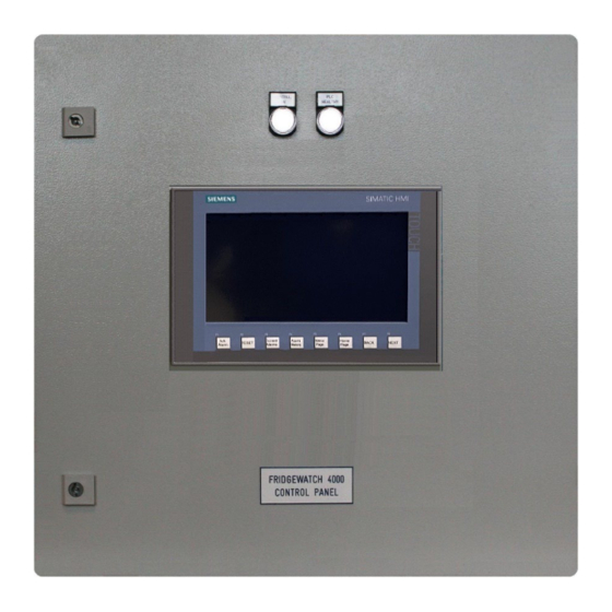
J&E Hall Fridgewatch 4000 Installation, Operating And Maintenance Manual (270 pages)
Controller Mk2 Software Version FW40Mk2P3.105 Onwards
Brand:
J&E Hall
| Category:
Controller
| Size: 9 MB
Table of Contents
Table of Contents
5
About this Publication
14
Safety Warnings and Symbols
14
Units of Measurement
14
Terminology
14
Additional Copies
14
Care and Protection of Fridgewatch
15
Anti-Static Precautions
15
Electrical Interference
15
Prolonged Storage
15
Abbreviations
16
Table 1 Abbreviations
16
General Description
17
Standalone Versions
17
Table 2 Fridgewatch 4000 Controller (Standalone Versions) - Technical Data
17
Human-Machine Interfaces (HMI) Displays
18
Fig 1 Fridgewatch 4000 Controller (Standalone Versions) - Front Panel and HMI Displays
18
Fig 2 Fridgewatch 4000 Controller (Standalone Standard Version) - Panel Internal Layout
19
Fig 3 Fridgewatch 4000 Controller (Standalone Standard and Harsh Environment Versions) - Enclosure
21
Fridgewatch 4000 Controller (Standalone Arrangement) - Mounting
22
Fig 4 Fridgewatch 4000 Controller (Standalone Arrangement) - Mounting
22
Fridgewatch 4000 Controller (Standalone Arrangement) - HMI Interface
23
Integrated Version
23
Application
23
Plant Control and Monitoring
23
Table 3 Analogues, Settings and Delay Times
23
Safety Monitoring
24
Options for Set Point Control
24
Set Point, Start and Stop Values, Second Set Point and Set Point Override
24
Operating Modes
24
Table 4 Options for Set Point Control
24
Limiting
25
Oil Management Systems
25
Auxiliary Control
25
Table 5 Set Point, Start and Stop Values, Second Set Point Value and Set Point Override
25
Principles of Control
26
Compressor Capacity Control
26
Hallscrew HSO 2000 Series Capacity Modulation by Slide Valves
26
Hallscrew HS 3100 to HSO 6200 Series Capacity Modulation by Slide Valves
26
Slide Valve Position Signal
27
Intermediate Load Outputs
27
Fig 5 Proportional and Integral (P + I) Control
28
Proportional and Integral (P + I) Control
29
Proportional Band
29
Integral Action Time
30
Fig 6 Integral Control Action
30
Set Point Temperature/Pressure
31
Evaporator Superheat Set Point/Liquid Level Set Point Value
31
Economiser Superheat Set Point
32
Starting and Stopping the Compressor
32
Fig 7 Possible Compressor Start/Stop and Capacity Control Modes
33
Control Philosophy for Compressor Operation after a Transmitter Failure
34
Capacity Control by Fridgewatch 4000
34
Auto Capacity Control
34
Remote Capacity Control
34
Manual Capacity Control
35
Limiting Inputs
35
Current Limiting
35
Suction Pressure Limiting
35
Discharge Pressure Limiting
35
Evaporator Cooled Medium Outlet Temperature Limiting
35
Table 6 Summary of Limiting Inputs and Associated Settings
35
Other Limiting Conditions
36
Levels of Limiting
36
Discharge High Pressure Trip Switch Function
36
Oil Management Systems
37
Table 7 Summary of Differential Pressure Sensing
37
Summary of Differential Pressure Sensing
38
Table 8 All Hallscrew Compressors - Oil Pressure Trips by Differential Pressure Switches
38
Table 9 HSO 2000 Series Compressors - Oil Pressure Trips by Transmitters
39
Demand Oil Pump
40
Table 10 HS 3100, HS 3200, HS 4200, HS 5200 and HS 6200 Series Compressors - Oil Pressure Trips by Transmitters
40
Oil Filling Pump
41
Fridgewatch System Controller and SCADA
42
Fridgewatch System Controller
42
SCADA System
42
Fig 8 Fridgewatch 4000 Controller Interface with Fridgewatch System Controller
43
Fig 9 Fridgewatch 4000 Controller Interface with SCADA
44
Installation
45
Digital Inputs and Outputs
45
Analogue Inputs - Installing Transmitters
45
Fig 10 Digital Inputs with Inputs Connected (Page 1 Illustrated)
45
Transmitter Wiring
46
Transmitter Enabling and Calibration
46
Using Fridgewatch 4000 to Drive Relays
46
Fig 11 Connecting Diodes
46
Fig 12 Transmitter Installation
47
Status Indicators
48
User Interface
48
Hard' and 'Soft' Display Function Buttons
48
Interface Common to Every Page
48
Time and Date
48
Access Level
48
Table 11 'Hard' and 'Soft' Display Function Buttons
48
Reset Required Indicator, Acknowledge and Reset Buttons
49
Current Alarms and Alarm History
49
Menu Page
49
Home Page and Digins
50
Back/Next, Analogue Inputs and P + I Diagnostics
50
Home Page
51
Fig 13 Home Page Example: Compressor in 'Off' Mode and SC1 and SC2 Not Configured
51
Fig 14 Home Page Example: Compressor 'Available
52
Fig 15 Home Page Example: Compressor 'Tripped
52
Start (Manual Start/Stop Only)
53
Load and Unload (Manual Capacity Control Only)
53
Controlled Stop/Stop Button RESET
53
System Diagnostics
54
Fig 16 System Diagnostics Page
54
Menu Page
55
Fig 17 Menu Page
55
Read-Only Pages
56
Digital Inputs
56
Fig 18 Digital Inputs Pages 1 to 3
56
Digital Outputs
58
Fig 19 Digital Outputs Pages 1 to 3
58
Analogue Inputs
60
Fig 20 Analogue Inputs Pages 1 to 4
60
Analogue Outputs
62
Fig 21 Analogue Outputs Pages 1 and 2
62
P + I Diagnostics
63
Fig 22 P + I Diagnostics Page
63
Primary/Secondary
64
Fig 23 Primary Compressor Page
64
Fig 24 Secondary Compressor Page
64
Trending and Logging Data
65
Fig 25 Trending and Logging Data Page
65
Fig 26 Trending Data - Evaporator Inlet and Outlet Temperature
65
Fig 27 Trending Data - Condenser Inlet and Outlet Temperature
66
Fig 28 Trending Data - Compressor Discharge, Suction and Oil Temperature
66
Fig 29 Trending Data - Compressor Discharge, Suction and Oil Injection Pressure
67
Fig 30 Trending Data - Compressor Capacity
67
Fig 31 Trending Data - Compressor Motor Current
68
Fig 32 Trending Data - Compressor Lub Oil and Net Oil Pressure, Oil Filter Differential Pressure
68
Fig 33 Trending Data - Compressor Discharge and Suction Superheat
69
Fig 34 Trending Example 1
70
Fig 35 Trending Example 1
70
Fig 36 Connecting to the CPU Via Ethernet Cable
72
Fig 37 Trending and Logging Data - Data Logging
73
Fig 38 Uploading Data Log Files
74
Clean Screen
76
Fig 39 Clean Screen
76
Operator Settings Pages
77
System Control Settings
77
Fig 40 System Control Settings Pages 1 to 3
77
Economiser Control Settings
79
Fig 41 Economiser Control Settings Pages 1 and 2
79
Liquid Injection Control Settings
80
Fig 42 Liquid Injection Control Settings Page
80
Evaporator and Oil Cooler Control Settings
81
Fig 43 Evaporator and Oil Cooler Control Settings Pages 1 and 2
81
Condenser Control Settings
82
Fig 44 Condenser Control Settings Page
82
Hot Gas Valve Control Settings
83
Fig 45 Hot Gas Valve Control Settings Page
83
Suction Pressure Limiting Control Settings
84
Fig 46 Suction Pressure Limiting Control Settings Page
84
Primary/Secondary Control Settings
85
Fig 47 Primary/Secondary Control Settings Page
85
Alarm, Limiting and Trip Settings, Delay Times
86
Fig 48 Alarm, Limit & Trip Settings Pages 1 to 11
86
Operating Mode
92
Fig 49 Operating Mode Page
92
Set Time and Date
93
Fig 50 Set Time and Date Page
93
Configuration Settings
94
ANIN Configuration
94
Fig 51 ANIN Configuration Pages 1 to 4
94
System Configuration Settings
97
Fig 52 System Configuration Pages 1 to 6
97
Hours Run and Number of Starts
101
Simulate Outputs
101
Fig 53 Hours Run and Number of Starts Page
101
Passwords
102
Password Security
102
Fig 54 Screen Page Categories and Colour Coding
102
Entering a Password
103
Fig 55 Password Logon
103
Commissioning
104
Supplying Power for the First Time
104
Commissioning - Sequence of Operations
104
Authority to Use Passwords
105
Inputting System Configuration Settings
105
Changing System Configuration Settings after Commissioning
106
Inputting Operator Settings
106
Changing Operator Settings after Commissioning
106
Operating Mode for the First Start
106
Fig 56 Viewing or Changing System Configuration Settings
107
Fig 57 Viewing or Changing Control Settings
108
Fig 58 Viewing or Changing Operator Settings
109
Display Messages
111
Information Only Messages
111
Alarm Messages
111
Trip Messages
111
Alarm, Trip and Information Only Messages
112
Suction Pressure: Alarm, Limiting and Trip
112
Suction Temperature High: Trip
112
Suction Superheat: Alarm
112
Table 12 Suction Pressure: Alarm, Limiting and Trip
112
Table 13 Suction Temperature High: Trip
112
Table 14 Suction Superheat: Alarm
112
Discharge Pressure High: Alarm, Limiting and Trip
113
Discharge Temperature High: Alarm and Trip
113
Discharge Superheat: Alarm
113
Table 15 Discharge Pressure High: Alarm, Limiting and Trip
113
Table 16 Discharge Temperature High: Alarm and Trip
113
Table 17 Discharge Superheat: Alarm
113
Oil Differential Pressure at Start-Up (ODP2) Low: Trip
114
Oil Differential Pressure During Running (ODP1) Low: Alarm and Trip
114
Table 18 Oil Differential Pressure at Start-Up (ODP2) Low: Trip
114
Table 19 Oil Differential Pressure During Running (ODP1) Low: Alarm and Trip
114
Oil Filter Differential Pressure High: Alarm and Trip
115
Oil Injection Temperature High: Alarm and Trip
115
Lube Oil Temperature High: Alarm and Trip
115
Table 20 Oil Filter Differential Pressure High: Alarm and Trip
115
Table 21 Oil Injection Temperature High: Alarm and Trip
115
Table 22 Lube Oil Temperature High: Alarm and Trip
115
Oil Separator/Reservoir Level Low: Trip
116
Oil Drain Not Clear: Information and Trip
116
Compressor Slide Valve Position (Motor Speed) Error: Alarm
116
Compressor Failed to Unload: Trip
116
Table 23 Oil Separator/Reservoir Level Low: Trip
116
Table 24 Oil Drain Not Clear: Information and Trip
116
Table 25 Compressor Slide Valve Position (Motor Speed) Error: Alarm
116
Table 26 Compressor Failed to Unload: Trip
116
Condenser Cooling Medium Inlet Temperature: Alarm
117
Condenser Cooling Medium Outlet Temperature: Alarm
117
Condenser Cooling Medium Differential Pressure Low: Alarm and Trip
117
Evaporator Cooled Medium Inlet Temperature: Alarm
117
Table 27 Condenser Cooling Medium Inlet Temperature: Alarm
117
Table 28 Condenser Cooling Medium Outlet Temperature: Alarm
117
Table 29 Condenser Cooling Medium Differential Pressure Low: Alarm and Trip
117
Table 30 Evaporator Cooled Medium Inlet Temperature: Alarm
117
Evaporator Cooled Medium Outlet Temperature: Alarm, Limiting and Trip
118
Evaporator Cooled Medium Differential Pressure: Alarm and Trip
118
Table 31 Evaporator Cooled Medium Outlet Temperature: Alarm, Limiting and Trip
118
Table 32 Evaporator Cooled Medium Differential Pressure: Alarm and Trip
118
Evaporator Liquid Level: Alarm and Trip
119
Compressor Motor Current: Limiting
119
Compressor Motor Temperature High: Trip
119
Table 33 Evaporator Liquid Level: Alarm and Trip
119
Table 34 Compressor Motor Current: Limiting
119
Table 35 Compressor Motor Temperature High: Trip
119
Compressor Motor or Starter Failure
120
Table 36 Compressor Motor or Starter Failure
120
Oil Pump Motor or Starter Failure
121
Table 37 Oil Pump Motor or Starter Failure
121
Condenser Pump/Fan Motor or Starter Failure
122
Table 38 Condenser Pump/Fan Motor or Starter Failure
122
Evaporator Cooled Medium Pump Motor or Starter Failure
123
User Trip
123
Emergency Stop Pressed
123
Table 39 Evaporator Cooled Medium Pump Motor or Starter Failure
123
Table 40 User Trip
123
Table 41 Emergency Stop Pressed
123
Starting or Loading Inhibited
124
Force Unload
124
Table 42 Starting or Loading Inhibited
124
Table 43 Force Unload
124
External Controller Fault: Evaporator, Economiser, Oil Rectifier or Liquid Injection
125
User Input Faults 1 and 2 (Digins I301.4 and I301.5)
125
Table 44 External Controller Fault: Evaporator, Economiser, Oil Rectifier or Liquid Injection
125
Table 45 User Input Faults 1 and 2
125
Refrigerant Leak Detector
126
Transmitter out of Range
126
Table 46 Refrigerant Leak Detector
126
External Reset and Alarms, Clearing Alarms and Trips
127
External Alarm/Trip Acknowledge/Reset
127
External Audible and Visual Alarms
127
Compressor Healthy Signal
127
Identifying and Clearing Alarms and Trips
127
Normal Healthy Condition
127
Table 47 External Alarms Digouts Q201.5 and Q201.6 Behaviour
127
Alarm Condition
128
Acknowledge Alarm
128
Trip Event
128
Fig 59 Identifying and Clearing Alarms and Trips
129
Fig 60 Limiting, Alarm and Alarm History Screens
131
Operator Settings
132
System Control Settings
132
Set Point, Start and Stop Values
133
Stop-To-Start Time Differential
133
Proportional and Integral (P + I) Control
133
Compressor Unload Limit
134
Load and Unload Pulse Duration
134
Intermediate Load Outputs
135
Fig 61 Example of Using Intermediate Load Output 1
136
Variable Volume Ratio (VV ) Configuration for Hallscrew 5200 and 6200 Series Compressors
137
Table 48 Variable Volume Ratio (VV R ) Applications, Values for S20 and SC48
137
Economiser Control Settings
138
Fig 62 Cycle Time
139
Economiser Control Enable and Disable
140
Liquid Injection Control Settings
141
Evaporator and Oil Cooler Control Settings
143
Evaporator Control Settings
143
Oil Cooler Control Settings
145
Condenser Control Settings
146
Hot Gas Bypass Valve Control Settings
148
Primary/Secondary Control Settings
150
Suction Pressure Limiting Control Valve Settings
151
Alarm, Limiting and Trip Settings, Delay Times
153
Motor Current High
153
Discharge Pressure High
153
Suction Pressure Low
154
Fig 63 Discharge Pressure High: Settings ALT9, ALT10, ALT11, ALT12 and ALTT3
154
Suction Pressure High
155
Oil Differential Pressure Low at Start-Up
155
Fig 64 Suction Pressure Low: Settings ALT2, ALT3, ALT7, ALT8 and ALTT2
155
Oil Differential Pressure Low During Running
156
Oil Filter Differential Pressure High
157
Oil Injection Temperature High
157
Fig 65 Oil Differential Pressure Low During Running: Settings ALT14, ALT15, ALTT5, ALTT6 and ALTT27
157
Lube Oil Temperature High
158
Discharge Temperature High
158
Suction Temperature High
158
Condenser Cooling Medium Inlet Temperature High or Low
158
Condenser Cooling Medium Outlet Temperature High or Low
158
Condenser Cooling Medium Differential Pressure Low
159
Evaporator Cooled Medium Inlet Temperature High or Low
159
Evaporator Liquid Level
160
Fig 66 Condenser Cooling Medium Differential Pressure Low: Settings
160
ALT43, ALT44, ALTT23, ALTT31 and ALTT33
160
Evaporator Cooled Medium Outlet Temperature Low
161
Fig 67 Evaporator Liquid Level: Settings ALT51, ALT52, ALT53, ALTT34 and ALTT35
161
Evaporator Cooled Medium Outlet Temperature High
162
Evaporator Cooled Medium Differential Pressure High
162
Fig 68 Evaporator Cooled Medium Outlet Temperature Low: Settings
162
ALT24, ALT25, ALT26, ALT27 and ALTT11
162
Evaporator Cooled Medium Differential Pressure Low
163
Suction Superheat High
163
Suction Superheat Low
164
Discharge Superheat High
164
Fig 69 Evaporator Cooled Medium Differential Pressure Low: Settings
164
ALT33, ALT34, ALTT14, ALTT16 and ALTT32
164
Discharge Superheat Low
165
Unload Pulses Per Sample Time
165
Oil Drain Delay Time
165
User Trip Nuisance Trip Delay Time
165
Oil Separator/Reservoir Nuisance Trip Delay Time
165
Configuration Settings
166
ANIN Configuration, Calibration and Scaling
166
Transmitter Calibration Overview
166
Fig 70 Transmitter Calibration
166
Pressure Transmitter Calibration
167
Fig 71 Transmitter Calibration - Examples
167
Temperature Transmitter Calibration
168
Motor Current Transmitter Calibration
169
Compressor Slide Valve Position LVDT Calibration
169
System Configuration
170
Compressor Number
170
System Refrigerant
170
Table 49 System Refrigerant Type - Values for SC2
170
Compressor Drive
171
Compressor Number of Starts
171
Oil Management System
171
Oil Differential Pressure at Start-Up
171
Oil Differential Pressure During Running
172
Table 50 Oil Differential Pressure (ODP2) Sensing Defined - Values for SC7
172
Table 51 Oil Differential Pressure (Running) ODP1 Sensing Defined - Values for SC8
172
Oil Filter Differential Pressure
173
Table 52 Oil Filter Differential Sensing Defined - Values for SC9
173
Compressor Capacity Control Valve Type
174
Table 53 Capacity Control Valve Application and Operation - Values for SC10
174
Compressor Slide Valve Position/Motor Speed Correction
175
Fig 72 Slide Valve Position (Svp)/Motor Speed: Error Tolerance - Values for SC11
176
Slide Valve Position/Motor Speed Value for Minimum Load
177
Compressor Fails to Unload at Start
177
Control, Start and Stop Variables, Second Set Point
177
Run Enable Signal
178
Table 54 Run Enable Required in Different Operating Modes - Values for SC18
178
Compressor Start Time
179
Oil Pump Start Time and Minimum Run Time
179
Demand Oil Pump Start and Stop
179
Evaporator Pump Selection, Start and Run Times
180
Condenser Start Time and Run-On Time
180
Pump-Down
180
Oil Rectifier Enable
181
Economiser Superheat Control Enable
181
Evaporator Superheat or Liquid Level Control Enable
182
Liquid Injection Control Enable
182
Condensing Pressure Control Enable
182
Compressor Slide Valve Position/Motor Speed Definition
183
Operating Mode Indication
183
Communications
183
Table 55 Operating Mode Indication - Values for SC42
183
Hot Gas Bypass Valve or Suction Pressure Limiting Control Enable
184
Primary/Secondary
185
Variable Speed Drive
185
Measurement Units
185
Fig 73 Example of FW4000 Display Page in Metric and Imperial Units
186
Table 56 Metric Pressure Transmitter and Temperature Sensor Ranges Used with FW4000
186
Maintenance
187
Maintenance Check List
187
Spares
187
Table 57 Maintenance Check List
187
Fig 74 FW4000 Stand-Alone Version Internal Equipment Layout and Terminal Arrangement
188
Table 58 Fuses and Relays, Electronic Modules and HMI
189
Table 59 Residual Risk Register
190
Appendix 1 Residual Risk Register
190
Fig 75 Panel Isolator IQ1 for Incoming 24 V DC 10 Amp Supply
191
Fig 76 Terminal Nomenclature and Identification
191
Appendix 2 Wiring Connections
191
Fig 77 Slot 1 CPU on Board DIGINS, Addresses I100.0 to I101.5, ANIN 24 and ANOUT 6
192
Fig 78 Slot 2 CPU on Board DIGINS, Addresses I200.0 to I201.7
194
Fig 79 Slot 3 CPU on Board DIGINS, Addresses I300.0 to I301.7
196
Fig 80 Slot 1 CPU on Board DIGOUTS, Addresses Q100.0 to Q101.1
198
Fig 81 Slot 2 CPU on Board DIGOUTS, Addresses Q200.0 to Q201.7
200
Fig 82 Slot 3 CPU on Board DIGOUTS, Addresses Q300.0 to Q301.7
202
Fig 83 Slot 4 ANINS 0 to 3, ANOUTS 0 and 1
204
Fig 84 Slot 5 ANINS 4 to 7, ANOUTS 2 and 3
205
Fig 85 Slot 6 ANINS 8 to 11, ANOUTS 4 and 5
205
Fig 86 Slot 7 ANINS 12 to 15
207
Fig 87 Slot 8 ANINS 16 to 19
207
Fig 88 Slot 9 ANINS 20 to 23
207
Fig 89 RS 485 Communication Board
210
Table 60 RS 485 Termination and Bias
210
Table 61 Analogue Input ANIN 00/ANIN 25 Quick-Reference and Calculated Values
212
Appendix 3 Analogue Inputs and Outputs
212
Table 62 Analogue Inputs ANIN 00/ANIN 25 Transmitters
213
Table 63 Analogue Outputs ANOUT 00/ANOUT 07
213
Table 64 Digital Inputs I100.0/I301.7
214
Appendix 4 Digital Inputs and Outputs
214
Table 65 Digital Outputs Q100.0/Q301.7
216
Table 66 HMI Trip Display Messages
217
Appendix 5 HMI Display Messages
217
Table 67 HMI Alarm Display Messages
218
Table 68 HMI Limiting Display Messages
219
Table 69 HMI out of Range Display Messages
219
Table 70 HMI out of Range Display Messages
220
Table 71 SCADA Information: ANINS, Calculated Values, ANOUTS Etc
221
Appendix 6 SCADA Information
221
Table 72 SCADA Information: ANIN out of Range Flags
223
Table 73 SCADA Information: ALT Trip Flags
225
Table 74 SCADA Information: ALT Alarm Flags
226
Table 75 SCADA Information: Limiting Flags
227
Table 76 SCADA Information: Alarm Inhibit Flags
228
Table 77 SCADA Information: DIGINS
229
Table 78 SCADA Information: DIGOUTS
230
Table 79 SCADA Information: Communications
231
Table 80 SCADA Information: Data Received
231
Table 81 SCADA Information: Data Block 33 @ 4 Ma and Data Block 34 @ 20 Ma
232
Table 82 SCADA Information: Array 'Elapsed Time Array for HMI Data Block 53
233
Table 83 SCADA Information: Array 'Control Diagnostic Data
234
Table 84 System Control Setting Addresses S1/S23
235
Appendix 7 Control Setting Addresses
235
Table 85 Economiser Control Setting Addresses EC1/EC14
236
Table 86 Evaporator Control Setting Addresses E1/E12
236
Table 87 Condenser Control Setting Addresses C1/C10
237
Table 88 Liquid Injection Control Setting Addresses LI1/LI9
237
Table 89 Hot Gas Bypass Valve Control Setting Addresses HG1/HG8
237
Table 90 Primary/Secondary Control Setting Addresses PS1/PS5
238
Table 91 Oil Cooler Control Setting Addresses OC1/OC2
238
Table 92 Suction Pressure Limiting Control Valve Setting Addresses SPL1/SPL8
238
Table 93 Alarm, Limiting and Trip Setting Addresses ALT0/ALT53
239
Table 94 Alarm, Limiting and Trip Delay Time Setting Addresses ALTT0/ALTT35
241
Table 95 Analogue Input Configuration Setting Addresses ANIN 00/ANIN 25
242
Table 96 System Configuration Setting Addresses SC1/SC53
244
Table 97 Compressor Number/Compressor Serial Number Record
246
Appendix 8 Settings Record
246
Advertisement
Advertisement
Related Products
J&E Hall Fridgewatch 2000
J&E Hall Fridgewatch 2100
J&E Hall Categories
Heat Pump
Air Conditioner
Accessories
Controller
Air Compressor
More J&E Hall Manuals
Login
Sign In
OR
Sign in with Facebook
Sign in with Google
Upload manual
Upload from disk
Upload from URL