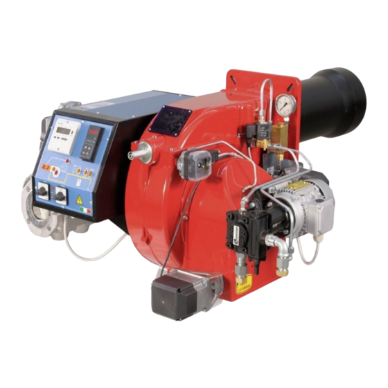
CIB UNIGAS KP60 Manual Of Installation - Use - Maintenance
Progressive and fully-modulating gas-heavy oil burners
Hide thumbs
Also See for KP60:
- Manual of installation - use - maintenance (136 pages) ,
- Manual of installation - use - maintenance (236 pages)

Related Manuals for CIB UNIGAS KP60


Summary of Contents for CIB UNIGAS KP60
- Page 1 KP60 KP72 - KP73 Progressive and fully-modulating gas - heavy oil burners MANUAL OF INSTALLATION - USE - MAINTENANCE BURNERS - BRUCIATORI - BRULERS - BRENNER - QUEMADORES - ГОРЕЛКИ M039193CE Rev. 4.9 11/2021...
- Page 2 DANGERS, WARNINGS AND NOTES OF CAUTION THIS MANUAL IS SUPPLIED AS AN INTEGRAL AND ESSENTIAL PART OF THE PRODUCT AND MUST BE DELIVERED TO THE USER. INFORMATION INCLUDED IN THIS SECTION ARE DEDICATED BOTH TO THE USER AND TO PERSONNEL FOLLOWING PRODUCT INSTALLATION AND MAINTENANCE.
- Page 3 3b) FIRING WITH GAS, LIGHT OIL OR OTHER FUELS DIRECTIVES AND STANDARDS Gas burners GENERAL European directives The burner shall be installed by qualified personnel and in compliance -Regulation 2016/426/UE (appliances burning gaseous fuels) with regulations and provisions in force; wrong installation can cause -2014/35/UE (Low Tension Directive) injuries to people and animals, or damage to property, for which the -2014/30/UE (Electromagnetic compatibility Directive)
- Page 4 Burner data plate Type Gas - Light oil burners For the following information, please refer to Model Year European Directives the data plate: S.Number -Regulation 2016/426/UE (appliances burning gaseous fuels) burner type and burner model: must be Output Oil Flow -2014/35/UE (Low Tension Directive) reported in any communication with the Fuel...
- Page 5 KP60 Model MD. S. (1) BURNER TYPE KP60 - KP72 - KP73 (2) FUEL M - Natural gas N - Heavy oil, viscosity <= 50cSt (7° E) @ 50° C D - Heavy oil, viscosity <= 400cSt (50° E) @ 50° C P - Petroleum, viscosity 89cSt (12°...
- Page 6 C.I.B. UNIGAS - M039193CE Specifications BURNERS KP60 Output min. kW max. kW 160 - 880 Fuel Natural gas Heavy oil Gas category see next paragraph Heavy oil viscosity See “Burner model identification” table 2 max Oil train inlet pressure Gas rate min.
- Page 7 C.I.B. UNIGAS - M039193CE BURNERS KP72 ..0.xx KP72 ..1.xx KP73 Output min. kW max. kW 330 - 1200 330 - 1550 320 - 2050 Fuel Natural gas Heavy oil Gas category see next paragraph Heavy oil viscosity See “Burner model identification” table 2 max Oil train inlet pressure Gas rate...
- Page 8 Overall dimensions - (mm) Burner flange Boiler recommended drilling template Reccomended counterflange 1213 493 1251 160 1213 493 1251 160 KP60 1213 493 1251 160 1213 493 1436 160 A COUNTERFLANGE IS MANDATORY:a gasket must be placed between the generator and the counterflange...
- Page 9 Reccomended counterflange O min O max O min O max Burner flange Boiler recommended drilling template Omin Omax KP72 xx-...0. 1299 1100 KP72 xx-...0. 1299 1230 KP72 xx-...0. 1299 1245 KP72 xx-...1. 1299 1225 KP72 xx-...1. 1299 1340 KP72 xx-...1. 1299 1345 *DN = gas valves size...
- Page 10 O min O max O min O max Boiler recommended drilling template Reccomended counterflange Omin Omax KP73 1320 140 495 1378 475 KP73 1320 140 495 1302 475 KP73 1320 140 495 1308 475 *DN = gas valves size NOTE: the overall dimensions are referred to burners provided with Siemens VGD valves. ATTENTION: the counterflange is an optional supplied only on request.
- Page 11 KP73 Fig. 1 3I2MD11 v1 Hydraulic diagram BY OTHERS BY BURNER CONSTRUCTOR oil inlet oil outlet gas inlet combustion air inlet ATTENTION: connect the oil return line to the degassing bottle (standard UNI 9248), as shown in the chapter "Recommendations to design heavy oil feeding plants" NOTE: POS 25, POS 31, POS 32, POS 33 are optional supply OIL TRAIN COMBUSTION AIR TRAIN...
- Page 12 KP60, KP72 Fig. 2 - 3I2MD21 v1 Hydraulic diagram ON BOARD ITEMS SUPPLIED LOOSE ITEMS LEGEND OIL TRAIN oil inlet Filter Pump and pressure governor Electrical motor oil outlet Electrical preheater tank Temperature probe Temperature probe Temperature probe Solenoid valve...
- Page 13 C.I.B. UNIGAS - M039193CE Performance curves KP60 KP72 ...0.xx KP72 ...1.xx KP73 To get the output in kcal/h, multiply value in kW by 860. Data are referred to standard conditions: atmospheric pressure at 1013mbar, ambient temperature at 15°C. NOTE: The performance curve is a diagram that represents the burner performance in the type approval phase or in the laboratory tests, but does not represent the regulation range of the machine.
- Page 14 C.I.B. UNIGAS - M039193CE Pressure in the Network / gas flow rate curves Gas burners KP60 /hGas rate Stm KP72 ...0.xx KP72 ...1.xx /hGas rate Stm /hGas rate Stm KP73 /hGas rate Stm Caution: the gas rate value is quoted on the x-axis, the related network pressure is quoted on the y-axis (pres- sure value in the combustion chamber is not included).
- Page 15 C.I.B. UNIGAS - M039193CE Combustion head gas pressure curves depending on the flow rate Curves are referred to pressure = 0mbar in the combustion head! The curves referred to the gas pressure in the combustion head, depending on the gas flow rate, are referred to the burner properly adjusted (percentage of residual O in the flues as shown in the “Recommended combustion values”...
- Page 16 C.I.B. UNIGAS - M039193CE Pressure in combustion head - gas rate curves KP60 ... Gas rate Stm KP65 KP72 Gas rate Stm Gas rate Stm KP73 Gas rate Stm...
- Page 17 C.I.B. UNIGAS - M039193CE MOUNTINGS AND CONNECTIONS Packing The burners are despatched in cardboard boxes or wooden cages whose dimensions are: 1730mmx 1280mm x 1020mm (L x P x H) Packing cases of this kind are affected by humidity and are not suitable for stacking. The fol- lowing are placed in each packing case: burner with gas train detached;...
- Page 18 C.I.B. UNIGAS - M039193CE SIDE UP SIDE DOWN 1 Burner flange (upper side indicated) 2 Bracket 3 Pre-heating tank on the burner...
- Page 19 C.I.B. UNIGAS - M039193CE GAS TRAIN CONNECTIONS The diagrams show the components of the gas trai included in the delivery and which must be fitted by the installer.The diagrams are in compliance with the current laws. WARNING: BEFORE EXECUTING THE CONNECTIONS TO THE GAS PIPE NETWORK, BE SURE THAT THE MANUAL CUTOFF VALVES ARE CLOSED.
- Page 20 C.I.B. UNIGAS - M039193CE Assembling the gas grain gas supply network ”direction” arrows for installation Keys 1A..1E Gasket Gas filter Gas valves group Bellows unit Manual valve Fig. 4 - Example of gas train To mount the gas train, proceed as follows: 1-a) in case of threaded joints: use proper seals according to the gas used;...
- Page 21 C.I.B. UNIGAS - M039193CE MULTIBLOC DUNGS MB-DLE 415..420 Mounting 1. Loosen screws A and B do not unscrew (Fig. 5 - Fig. 6). 2. unscrew screws C and D (Fig. 5 - Fig. 6). 3. Remove MultiBloc between the threaded flanges (Fig. 6). 4.
- Page 22 C.I.B. UNIGAS - M039193CE (spring) (cap) Fig. 12 Siemens VGD valves with SKP actuator: The pressure adjusting range, upstream the gas valves group, changes according to the spring provided with the valve group. 0 - 22 15 - 120 100 - 250 Performance range (mbar) neutral yellow...
- Page 23 C.I.B. UNIGAS - M039193CE Double-pipe and single-pipe system The pumps that are used can be installed both into single-pipe and double-pipe systems. Single-pipe system: a single pipe drives the oil from the tank to the pump’s inlet. Then, from the pump, the pressurised oil is driven to the nozzle: a part comes out from the nozzle while the othe part goes back to the pump.
- Page 24 C.I.B. UNIGAS - M039193CE Oil pumps KP60 - KP65 - KP72: Pumps for heavy-oil viscosity up to 7° E at 50° C (burner model MN.) Suntec E4 - E6 - E7 1001 Oil viscosity 2.8 ÷ 450 cSt Oil temperature 0 ÷...
- Page 25 C.I.B. UNIGAS - M039193CE KP73: Suntec TA.. Oil viscosity 3 ÷ 75 cSt Oil temperature 0 ÷ 150°C Min. suction pressure - 0.45 bar to avoid gasing Max. suction pressure 5 bar Max. return pressure 5 bar Rotation speed 3600 rpm max. Inlet G1/2 To the nozzle G1/2 Return G1/2...
- Page 26 C.I.B. UNIGAS - M039193CE RECOMMENDATIONS TO DESIGN HEAVY OIL FEEDING PLANTS This paragraph is intended to give some suggestions to make feeding plants for heavy oil burners. To get a regular burner operation, it is very important to design the supplying system properly. Here some suggestions will be mentioned to give a brief description. The term “heavy oil”...
- Page 27 C.I.B. UNIGAS - M039193CE Viscosity units conversion table Saybolt Cinematics Saybolt Redwood Engler Degrees Seconds Redwood Seconds viscosity Seconds Seconds no.1 (°E) Universal no..2 (Admiralty) Centistokes (cSt) Furol (SSF) (Standard) (SSU) 2.56 1.16 32.1 1.31 36.2 1.58 44.3 5.83 10.3 1.88 52.3 6.77...
- Page 28 C.I.B. UNIGAS - M039193CE VISCOSITY vs TEMPERATURE DIAGRAM FOR COMBUSTIBLE OILS 1000 PUMPING LIMIT TEMPERATURE (°C) LIGHT OIL 1,3°E AT 20°C HEAVY OIL 2,4°E AT 50°C HEAVY OIL 4°E AT 50°C HEAVY OIL 7,5°E AT 50°C HEAVY OIL 10°E AT 50°C HEAVY OIL 13°E AT 50°C HEAVY OIL 22°E AT 50°C HEAVY OIL 50°C...
- Page 29 C.I.B. UNIGAS - M039193CE Indicative diagram showing the oil temperature at burner pump inlet vs. oil viscosity Example: if the oil has a 50°E @ 50°C viscosity, the oil temperature at the pump inlet should be 80°C (see diagram). OIL TEMPERATURE FOR PUMP FEEDING TEMPERATURE (°C) Fig.
- Page 30 C.I.B. UNIGAS - M039193CE...
- Page 31 C.I.B. UNIGAS - M039193CE...
- Page 32 C.I.B. UNIGAS - M039193CE Electrical connections Respect the basic safety rules. make sure of the connection to the earthing system. do not reverse the phase and neutral connections. fit a differential thermal magnet switch adequate for connection to the mains. ATTENTION: before executing the electrical connections, pay attention to turn the plant’s switch to OFF and be sure that the burner’s main switch is in 0 position (OFF) too.
- Page 33 C.I.B. UNIGAS - M039193CE Connecting the oil heating resistors 2.4 - 4.5 kW 8 - 12 kW 400 V 230V 400 V 230V Fig. 19 Fig. 20 18 - 24 kW ELECTRIC MOTOR CONNECTION 400 V 230V 400 V 230V Fig.
- Page 34 C.I.B. UNIGAS - M039193CE AIR FLOW AND FUEL ADJUSTMENT Adjustments - brief description Adjust the air and gas flow rates at the maximum output (“high flame”) first, by means of the air damper and the adjusting cam respec- tively. Check that the combustion parameters are in the suggested limits. .Check the flow rate measuring it on the counter or, if it was not possible, verifying the combustion head pressure by means of a differential pressure gauge.
- Page 35 C.I.B. UNIGAS - M039193CE ADJUSTMENTS FOR GAS OPERATION check the fan motor rotation. Only for burners provided with Multibloc MB-DLE gas valves: before starting the burner up, set the slow opening. To set the slow opening, remove cover T, reverse it upside down and use it as a tool to rotate screw VR. Clockwise rotation reduces start flow rate, anticlockwise rotation increases it.
- Page 36 C.I.B. UNIGAS - M039193CE 10 If necessary, adjust the combustion head position (see the dedicated paragraph).. Attention! if it is necessary to change the head position, repeat the air and gas adjustments described above. 11 The air and gas rate are now adjusted at the maximum power stage, go on with the point to point adjustement on the SV1 (gas side) adjusting cam as to reach the minimum output point.
- Page 37 C.I.B. UNIGAS - M039193CE Fig. 24 Fig. 25 Output flange 1 Electrical connection for valves 10 Test point connection M4 downstream of valve 2 2 Operation display (optional) 11 Gas flow direction 3 Pressure governor closing tap 12 Test connection G 1/8 downstream of valve 1, on both sides 4 Start setting cap 13 Vent nozzle pressure regulator 5 Hydraulic brake and rate regulator...
- Page 38 C.I.B. UNIGAS - M039193CE To calibrate the maximum pressure switch, proceed as follows according to its mounting position: remove the pressure switch plastic cover; if the maximum pressure switch is mounted upstreaam the gas valves: measure the gas pressure in the network, when flame is off; by means of the adjusting ring nut VR, set the value read, increased by the 30%.
- Page 39 C.I.B. UNIGAS - M039193CE Adjusting the combustion head KP60 - KP72 Only if necessary, change the combusiton head position. The burner is factory-set with the head in its MAX position (maximum output). To let the burner operate at a lower output, turn clockwise the VRT screw and move progressively the combustion head back towards the MIN position.Attention! if it is necessary to change the head position, repeat the air and gas adjustments described above.
- Page 40 C.I.B. UNIGAS - M039193CE ADJUSTMENTS FOR OIL OPERATION Before starting up the burner, make sure that the return pipe to the tank is not obstructed. Any obstruction would cause the pump seal to break. ATTENTION: before starting the burner up, be sure that the manual cutoff valves are open. Be sure that the mains switch is closed.
- Page 41 C.I.B. UNIGAS - M039193CE The heavy oil flow rate can be adjusted choosing a by-pass nozzle that suits the boiler/utilisation output and setting the delivery and return pressure values according to the ones quoted on the chart below and the diagram on Fig. 30-Fig. 31. FLUIDICS NOZZLE: REFERENCE DIAGRAM (INDICATIVE ONLY) Atomisation angle FLOW RATE kg/h...
- Page 42 Then move progressively the microswitch to higher values until it reaches the high flame position; always check the combustion values and eventually adjusting the oil pressure (see next step). Pressure gauge port KP60-KP72 Pressure gauge port Pressure gauge port KP73 Only if necessary, adjust the supply pressure as follows;insert a pressure gauge into the port shown on figure and act on on the...
- Page 43 C.I.B. UNIGAS - M039193CE Turn the burner off; then start it up again. If the adjustment is not correct, repeat the previous steps.
- Page 44 C.I.B. UNIGAS - M039193CE PART II: OPERATION LIMITATIONS OF USE THE BURNER IS AN APPLIANCE DESIGNED AND CONSTRUCTED TO OPERATE ONLY AFTER BEING CORRECTLY CONNEC- TED TO A HEAT GENERATOR (E.G. BOILER, HOT AIR GENERATOR, FURNACE, ETC.), ANY OTHER USE IS TO BE CONSIDE- RED IMPROPER AND THEREFORE DANGEROUS.
- Page 45 C.I.B. UNIGAS - M039193CE Burner front panel KP60-72 High flame mode indicating light Low flame mode indicating light Ignition transformer operation Main switch/operation mode (Gas / Oil) Fan motor overload tripped intervention Burner lockout iindicationg light Stand-by mode indicating light...
- Page 46 C.I.B. UNIGAS - M039193CE PART III: MAINTENANCE At least once a year carry out the maintenance operations listed below. In the case of seasonal servicing, it is recommended to carry out the maintenance at the end of each heating season; in the case of continuous operation the maintenance is carried out every 6 months.
- Page 47 C.I.B. UNIGAS - M039193CE Self-cleaning filter Fitted only on high viscosity oil burners. Periodically turn the knob to clean the filter. Replacing the spring in the gas valve group To replace the spring in the gas valve group,proceed as follows: Carefully twist the protection cap 1 and the O-ring 2.
- Page 48 C.I.B. UNIGAS - M039193CE Electrodes Adjustment (KP60, KP72) Important Note: Check the ignition and detection electrodes after removing/adjusting the combustion head. ATTENTION: avoid the ignition and detection electrodes to contact metallic parts (blast tube, head, etc.), other- wise the boiler’s operation would be compromised. Check the electrodes position after any intervention on the combustion head.
- Page 49 C.I.B. UNIGAS - M039193CE Removing the combustion head (KP73) Remove the cover H. Slide the photoresistance out of its housing. Unscrew the V screws that block the gas collector G, loosen the three jionts E and remove the ass.y as shown on the following picture. Clean the combustion head by means fo a vacuum cleaner;...
- Page 50 C.I.B. UNIGAS - M039193CE Adjusting the electrodes position (KP73) Adjust the electrodes position, according to the quotes shown in the next picture Keys electrodes air pipe ignition gas pipe nozzle Fig. 31 Checking the detection current To check the detection signal follow the scheme in the picture below. If the signal is less than the value indicated, check the position of the detection electrode or detector, the electrical contacts and, if necessary, replace the electrode or the detector.
- Page 51 C.I.B. UNIGAS - M039193CE TROUBLESHOOTING Heavy oil operation MAIN SWITCH OPEN LINE FUSE INTERVENTION MAX. PRESSURE SWITCH FAULT FAN THERMAL CUTOUT INTERVENTION AUXILIARY RELAIS FUSES INTERVENTION CONTROL BOX FAULT SERVOCONTROL FAULT SMOKEY FLAME IGNITION TRANSFORMER FAULT IGNITION ELECTRODE DIRTY OR WRONG POSITIONED DIRTY NOZZLE FUEL SOLENOID VALVE DEFECTIVE...
- Page 52 C.I.B. UNIGAS - M039193CE Gas operation...
- Page 53 C.I.B. UNIGAS - M039193CE WIRING DIAGRAMS Refer to the attached wiring diagrams. WARNING 1 - Electrical supply 230V / 400V 50Hz 3N a.c. 2 - Do not reverse phase with neutral 3 - Ensure burner is properly earthed...
- Page 54 APPENDIX SIEMENS LFL 1.3.. CONTROL BOX consent to start-up by means of the thermostat or pressostat "R" start-up program Automatic programme in the event of interruption and indication of posi- tion when interrupted normal burner operation By default, in the event of any kind of interruption, the flow of fuel is imme- regulation stop caused by "R"...
- Page 55 Ionisation monitor Twin-tube burners (**) voltage in detector electrode Preignition time until the all clear to the pilot burner valve at normal working 330V ±10% terminal 17. test 380V ±10% First safety time (pilot flame strenght); at the end of the safety time short circuit current max.
- Page 56 Programmer diagram pre-ventilation time limit contact switch for damper OPEN position safety time block remote signal '1st safety time main relay (working network) with contacts "ar" pre-ignition time Monitor fuse 'pre-ignition time block relay with "br" contacts interval for creating current between terminals 18 and 19 fuel valve 'interval for creating current between terminals 17 and 19 reset button...
- Page 60 C.I.B. UNIGAS S.p.A. Via L.Galvani, 9 - 35011 Campodarsego (PD) - ITALY Tel. +39 049 9200944 - Fax +39 049 9200945/9201269 web site: www.cibunigas.it - e-mail: cibunigas@cibunigas.it Note: specifications and data subject to change. Errors and omissions excepted.
- Page 61 WIRING DIAGRAMS SE05-706: progressive burners SE05-709: fully-modulating burners E039193CB Re . 1 0 /201...
- Page 62 ELECTRICAL WIRING DIAGRAMS WIRING DIAGRAM Cod. 05-706 - Progressive burners WIRING DIAGRAM Cod. 05-709 - Fully-modulating burners Keys Oil pump contactor coil Contactor coil for oil pre-heater resistors Fan motor contactor coil Auxiliary contacts on oil pump motor contactor Auxiliary contacts on oil pre-heater resistor contactor Operation selector 0) Off - 1) Gas - 2) Oil Manual operation selector 0) Stop - 1) High flame - 2) Low flame - 3) Automatic Contacts on oil pump motor contactor...
- Page 63 SD-0÷10V Probe connection with signal 0÷10V SD-PRESS Pressure probe connection (SIEMENS QBE620...) SD-TEMP Temperature probe connection (Pt1000 or SIEMENS QAE2..-QAC2..) SQL/SQM/STM Actuator for air damper Series of thermostats or pressure switches Ignition transformer Hi-Lo flame thermostat (if fitted remove the connection between terminals 6 and 7 on terminal board MA) Thermocoupling Plant enabling thermostat Oil enabling thermostat...
- Page 85 RWF55.5X & RWF55.6X User manual M12926CA Rel.0.2 11/2023...
- Page 86 DEVICE INSTALLATION Fixing system Drilling dimensions:...
- Page 87 FRONT PANEL Burner release Controlling element CLOSED/stage 1 Controlling element OPEN/stage 2 Operating mode 2-stage Actual value display (red) and parameter value USB led Comunication via interface Operating mode 2-stage Thermal shock protection Alarm function Decrease value Increase value ESC button Enter button...
- Page 88 NAVIGATION MENU User Level - Opr Parameter level SP1 or SP2 (editable) dSP readable and editable through bin1 = 2 InP1 or y (only display) Basic display Parameter level - PArA Pb1, dt, rt, db, tt Heating controllerHYS1 , HYS2 , HYS3 Cooling controller HYS4 , HYS5 , HYS6...
- Page 89 PID parameters set and modifications (PArA): Push Enter button, on the green display Opr appears; using the down arrow, scroll until group PArA is reached and push Enter. On the green display Pb1 e appears and on the red one the set parameter. Push is sequence the down or up arrow the menu is scrolled. Push Enter to select and the arrows to choose the desired value.
- Page 90 Setting the kind of sensor to be connected to the device: Push the Enter button: on the lower display (green) Opr appears. Using the up and down arrows find ConF. Push Enter to confirm. Now on the green display the group InP appears. Push Enter and InP1 is displaied. Enter to confirm.You are inside InP1; the green display shows Sen1 (sensor type), while the red display shows the chosen sensor code Push Enter to enter the Sen1 parameter, then choose the desired sensor using the arrows.
- Page 91 ConF > InP >InP2 Input 2 : this input can be used to specify an external setpoint or carry out setpoint shifting Parameter Value Description no function FnC2 external setpoint (display SPE) setpoint shifting (display dSP) angular positioning feedback SEn2 0 ÷...
- Page 92 ConF > Cntr Here, the type of controller, operating action, setpoint limits and presettings for self-optimization are selected Parameter Value Description 3-position controller (open-stop-close) CtYP ontroller type continuative action controller (0 ÷10V 4 ÷ 20mA) heating controller CACt control action cooling controller minimum set-point scale -1999..0..+9999...
- Page 93 Alarm functionAF The alarm function can be used to monitor the analog inputs. If the limit value is exceeded, multifunctional relay K6 (terminals 6N and 6P) is activated (depending on the switching characteristic) The alarm function can have different switching functions (lk1 to lk8) and can be set to a deviation from the active setpoint or to a fixed limit value Limit value AL relative to setpoint (x) Fixed limit value AL...
- Page 94 ConF > AF Parameter Value Description Without function FnCt type of control InP1 monitored input Ik1 = InP1 monitored input Ik2 = InP1 monitored input Ik3 = InP1 monitored input Ik4 = InP1 monitored input Ik5 = InP1 monitored input Ik6 = InP1 monitored input...
- Page 95 ConF > binF This setting decides on the use of the binary inputsD1, D2, DG Parameter Value Description without function bin1 binary imput terminals set-point changeover (SP1 / SP2) – D1) set-point shift (Opr > dSP parameter = value of set-point modify) 2 = l input alarm changeover of operating mode...
- Page 96 ConF > IntF The controller can be integrated into a data network using an optional RS-485 (terminals R+ and R-) interface or an optional Profibus DP interface(only modelRWF55.6x terminalsC1-C2-C3-C4) Parameter Value Description 0 = 4800 baud bdrt baudrate 1 = 9600 baud 2 = 19200 baud 3 = 38400 baud Address in the data network...
- Page 97 Display of software version : The software version is shown by pushing Enter + UP arrow on the upper display Weather-compensated setpoint shifting(climatic regulation): The RWF55 can be configured so that weather-compensated setpoint shifting is activated when an LG-Ni1000 outside sensor or a Pt1000 is connected (see parameter InP3).
- Page 98 Modbus interface The tables that follow in this chapter specify the addresses of the readable and writable words that the customer is able to access. The customer may read and/or write the values using SCADA programs, PLCs, or similar. The entries under Access have the following meanings: R/O Read Only, value can only be read R/W Read/Write, value can be read and written The number of characters specified under Data type in the case of character strings includes the final \0.
- Page 99 Configuration level Address Access Data type Signal reference Parameter 0x3426 Float SCL1 Start of display input 1 0x3428 Float SCH1 End of display input 1 0x3432 Float SCL2 Start value input 2 0x3434 Float SCH2 End value input 2 0x3486 Float Start of setpoint limitation 0x3488...
- Page 100 Dati dell’apparecchio Address Access Data type Signal reference Parameter 0x8000 Char12 Software version 0x8006 Char14 VdN number Stato dell’apparecchio Address Access Data type Signal reference Parameter 0x0200 Word Outputs and states Bit 0 Output 1 Bit 1 Output 3 Bit 2 Output 2 Bit 3 Output 4...
- Page 101 Electric connections : With 7 pins connector version With terminals version Corrispondences bornes entre RWF55.5x y RWF40.0x0Matches terminals betweenRWF55.5x and RWF40.0x0...
- Page 102 Parameters summarising for RWF55.xx : ConF ConF Navigation menù Inp1 Cntr diSP PArA Types of probe SEn1 OFF1 Unit dECP Pb. 1 HYS1 (*) HYS3 (*) SP1 (*) Siemens QAE2120… needless needless 80 °C Siemens QAM2120.. needless needless -2,5 40°C Pt1000 (130°C max.) needless needless...
- Page 103 APPENDIX: PROBES CONNECTION To assure the utmost comfort, the control system needs reliable information, which can be obtained provided the sensors have been installed correctly. Sensors measure and transmit all variations encountered at their location. Measurement is taken based on design features (time constant) and according to specific operating conditions.With wiring run in raceways, the sheath (or pipe) containing the wires must be plugged at the sensor's terminal board so that currents of air cannot affect the sensor's measurements.
- Page 104 Duct or pipe sensors Installing pressure sensors Installing temperature sensors A - installation on ducts carrying fluids at max. temperature 80°C For measuring outlet air: B - installation on ducts at temperature over 80°C and for refrigerants "after delivery fan or C - installation on ducts at high temperatures : "after coil to be controlled, at a distance of at least 0,5 m ·"increase length of siphon...
- Page 105 Immersion or strap-on sensors Immersion probes installation Sensors must be installed on the stretch of pipe in which fluid circula- tes all the time. The rigid stem (sensing element doing the measuring) must be inser- ted by at least 75mm and must face the direction of flow. Recommended locations: on a bend or on a straight stretch of pipe but tilted by 45°...
- Page 106 Duct pressure switches and sensors Installing differential pressure probes for air Basic principles Measuring static pressure(i.e. pressure exerted by air on pipe walls) A - Control a filter (clogging) Measuring dinamic pressure B - Control a fan (upstream/downstream) Legend Kg/m3, specific weight of air m/s, air speed 9.81 m/s2 gravity acceleration mm C.A., dynamic pressure...
- Page 108 Note: Specifications and data subject to change. Errors and omissions excepted.
- Page 109 MANUALE USER SUPPORT MULTI-THERMOSTAT MCX06C MCX06C is a multi-thermostat with four 100k NTC inputs. It can control up to 4 temperatures showing them (not more than 2 at the same time) on a couple of displays. It is used to check and adjust oil heater temperatures. it works as follows: as soon as the burner control gives the GO to the digital 1 input (terminals DI1-COM), the adjustment program runs (the relevant LED is ON).
- Page 110 Connections from terminal side : 24V AC Probe connection: input AI1 = probe Pb1 = set-point “tr” = oil heater temperature probe; input AI2 = probe Pb2 = set-point “tCI” = plant consent temperature probe (when installed); input AI3 = probe Pb3 = set-point “OIL” = oil heater output temperature probe (PID regulation); input AI4 = probe Pb4 = set-point “tcn”...
- Page 111 (tCI - Pb2 probe only for mechanical atomizing burners) Menu : To enter the menu below, keep pushing ENTER for more than 3 s. Menu code Sub-menu code Function Notes Probes values You can see in sequence the 4 probe values (UP and DOWN keys): the probe code is on display A (Pb1,..., Pb4) and the probe value is on display B (not fitted or out...
- Page 112 submenu CnF - configuration parameters group : Visibility Password Modbus Menu Parameter Description Additional description Default U.M. condition level index CONFIGURATION Analog Input 1 This parameter enables or disables the Probe 1 Presence probe Calibration Probe 1 Don't modify it -20,0 20,0 °C...
- Page 113 Visibility Modbus Menu Parameter Description Additional description Default U.M. condition Level index Autotuning Output temperature hysteresis Don't modify it 50,0 °C Startup number Don't modify it Measurement cycles number Don't modify it Max. differential command Don't modify it exit 0,01 10,00 10,00 Differential reduction exit...
- Page 114 Submenu REG – regulation parameters group : Visibility Modbus Menu Parameter Description Additional description Default U.M. condition Level index REGULATION Probe 1 Set-point Probe 1 Don't modify it (Tank resistor) -50,0 200,0 °C Probe 1 - Low Temperature Alarm Don't modify it Threshold -50,0 200,0...
- Page 115 Visibility Modbus Menu Parameter Description Additional description Default U.M. condition Level index Overshooting for Integral action Don't modify it (Oil tank exit) 1000 Derivative action enabling Don't modify it (Oil tank exit) Filtering factor for derivative action Don't modify it (Oil tank exit) Duty cicle PWM for output DO3 Don't modify it...
- Page 116 Alarms & Warning: When the red triangle on the top left lights, one or more alarms are activated. When the red key on the left lights, the output N05-C5 is active and the relay KTRS switches the resistors OFF. Check the reason, correct the failure and, as soon as the temperature is lower than trS, reset it through ALA/rES . In order to show active alarms and warnings, select the relevant menu through ALA/Act.and, using the UP and DOWN buttons, scroll the lines.
Need help?
Do you have a question about the KP60 and is the answer not in the manual?
Questions and answers