Table of Contents
Advertisement
https://tehnoteka.rs
Uputstvo za upotrebu (EN)
ASRock H610M-HVS/M.2 R2.0 matična ploča
Tehnoteka je online destinacija za upoređivanje cena i karakteristika bele tehnike,
potrošačke elektronike i IT uređaja kod trgovinskih lanaca i internet prodavnica u Srbiji.
Naša stranica vam omogućava da istražite najnovije informacije, detaljne karakteristike
i konkurentne cene proizvoda.
Posetite nas i uživajte u ekskluzivnom iskustvu pametne kupovine klikom na link:
https://tehnoteka.rs/p/asrock-h610m-hvsm2-r20-maticna-ploca-akcija-cena/
Advertisement
Table of Contents

Related Manuals for ASROCK H610M-HDV/M.2 R2.0


Summary of Contents for ASROCK H610M-HDV/M.2 R2.0
- Page 1 Uputstvo za upotrebu (EN) ASRock H610M-HVS/M.2 R2.0 matična ploča Tehnoteka je online destinacija za upoređivanje cena i karakteristika bele tehnike, potrošačke elektronike i IT uređaja kod trgovinskih lanaca i internet prodavnica u Srbiji. Naša stranica vam omogućava da istražite najnovije informacije, detaljne karakteristike i konkurentne cene proizvoda.
- Page 3 In no event shall ASRock, its directors, officers, employees, or agents be liable for any indirect, special, incidental, or consequential damages (including damages for loss of profits, loss of business, loss of data, interruption of business and the like), even if ASRock has been advised of the possibility of such damages arising from any defect or error in the documentation or product.
- Page 4 The terms HDMI® and HDMI High-Definition Multimedia Interface, and the HDMI logo are trademarks or registered trademarks of HDMI Licensing LLC in the United States and other countries. INTEL END USER SOFTWARE LICENSE AGREEMENT IMPORTANT - READ BEFORE COPYING, INSTALLING OR USING. LICENSE.
- Page 5 Licensee’s intellectual property rights, to incorporate or otherwise utilize those comments and suggestions. TERMINATION OF THIS LICENSE. Intel or the sublicensor may terminate this license at any time if Licensee is in breach of any of its terms or conditions. Upon termination, Licensee will immediately destroy or return to Intel all copies of the Software.
- Page 6 ASRock follows the green design concept to design and manufacture our products, and makes sure that each stage of the product life cycle of ASRock product is in line with global environmental regulations. In addition, ASRock disclose the relevant information based on regulation requirements.
-
Page 7: Table Of Contents
M.2_SSD (NGFF) Module Installation Guide (M2_2) Chapter 3 Software and Utilities Operation Installing Drivers ASRock Motherboard Utility (A-Tuning) 3.2.1 Installing ASRock Motherboard Utility (A-Tuning) 3.2.2 Using ASRock Motherboard Utility (A-Tuning) ASRock Live Update & APP Shop 3.3.1 UI Overview 3.3.2 Apps... - Page 8 3.3.4 Setting Chapter 4 UEFI SETUP UTILITY Introduction EZ Mode Advanced Mode 4.3.1 UEFI Menu Bar 4.3.2 Navigation Keys Main Screen OC Tweaker Screen Advanced Screen 4.6.1 CPU Configuration 4.6.2 Chipset Configuration 4.6.3 Storage Configuration 4.6.4 Super IO Configuration 4.6.5 ACPI Configuration 4.6.6 USB Configuration 4.6.7 Trusted Computing Tools...
-
Page 9: Chapter 1 Introduction
ASRock’s website without further notice. If you require technical support related to this motherboard, please visit our website for specific information about the model you are using. You may find the latest VGA cards and CPU support list on ASRock’s website as well. ASRock website http://www.asrock.com. -
Page 10: Specifications
Memory • 2 x DDR4 DIMM Slots • Supports DDR4 non-ECC, un-buffered memory up to 3200* * Please refer to Memory Support List on ASRock's website for more information. (http://www.asrock.com/) • Supports ECC UDIMM memory modules (operate in non- ECC mode) • Max. - Page 11 H610M-HDV/M.2 R2.0 H610M-HVS/M.2 R2.0 • Supports DisplayPort 1.4 with DSC (compressed) max. resolution up to 8K (7680x4320) @ 60Hz / 5K (5120x3200) @ 120Hz • Supports D-Sub with max. resolution up to 1920x1200 @ 60Hz • Supports HDCP 2.3 with HDMI 2.1 TMDS Compatible and DisplayPort 1.4 Ports...
- Page 12 2242/2260/2280 PCIe Gen3x4 (32 Gb/s) mode* • 4 x SATA3 6.0 Gb/s Connectors * Supports NVMe SSD as boot disks * Supports ASRock U.2 Kit Connector • 1 x SPI TPM Header • 1 x Chassis Intrusion and Speaker Header • 1 x CPU Fan Connector (4-pin)
- Page 13 • ErP/EuP ready (ErP/EuP ready power supply is required) * For detailed product information, please visit our website: http://www.asrock.com Please realize that there is a certain risk involved with overclocking, including adjusting the setting in the BIOS, applying Untied Overclocking Technology, or using third-party overclocking tools.
-
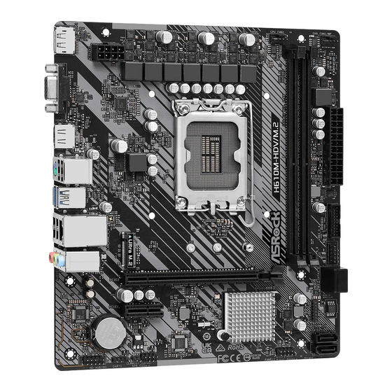
Page 14: Motherboard Layout
1.3 Motherboard Layout H610M-HDV/M.2 R2.0:... - Page 15 H610M-HDV/M.2 R2.0 H610M-HVS/M.2 R2.0 H610M-HVS/M.2 R2.0:...
- Page 16 No. Description ATX 12V Power Connector (ATX12V1) CPU Fan Connector (CPU_FAN1) 2 x 288-pin DDR4 DIMM Slots (DDR4_A1, DDR4_B1) Chassis/Water Pump Fan Connector (CHA_FAN1/WP) ATX Power Connector (ATXPWR1) USB 3.2 Gen1 Header (USB3_3_4) USB 2.0 Header (USB_5_6) SATA3 Connector (SATA3_2) (Upper), SATA3 Connector (SATA3_3) (Lower) SPI TPM Header (SPI_TPM_J1) SATA3 Connector (SATA3_1) SATA3 Connector (SATA3_0)
-
Page 17: I/O Panel
H610M-HDV/M.2 R2.0 H610M-HVS/M.2 R2.0 1.4 I/O Panel H610M-HDV/M.2 R2.0: No. Description No. Description USB 2.0 Ports (USB_1_2) USB 3.2 Gen1 Ports (USB3_1_2) LAN RJ-45 Port* PS/2 Mouse/Keyboard Port Line In (Light Blue)** HDMI Port Front Speaker (Lime)** D-Sub Port Microphone (Pink)** DisplayPort 1.4... - Page 18 * There are two LEDs on each LAN port. Please refer to the table below for the LAN port LED indications. ACT/LINK LED SPEED LED LAN Port Activity / Link LED Speed LED Status Description Status Description No Link 10Mbps connection Blinking Data Activity Orange...
-
Page 19: Chapter 2 Installation
H610M-HDV/M.2 R2.0 H610M-HVS/M.2 R2.0 Chapter 2 Installation This is a Micro ATX form factor motherboard. Before you install the motherboard, study the configuration of your chassis to ensure that the motherboard fits into it. Pre-installation Precautions Take note of the following precautions before you install motherboard components or change any motherboard settings. -
Page 20: Installing The Cpu
2.1 Installing the CPU 1. Before you insert the 1700-Pin CPU into the socket, please check if the PnP cap is on the socket, if the CPU surface is unclean, or if there are any bent pins in the socket. Do not force to insert the CPU into the socket if above situation is found. Otherwise, the CPU will be seriously damaged. - Page 21 H610M-HDV/M.2 R2.0 H610M-HVS/M.2 R2.0...
- Page 22 Please save and replace the cover if the processor is removed. The cover must be placed if you wish to return the motherboard for after service.
-
Page 23: Installing The Cpu Fan And Heatsink
H610M-HDV/M.2 R2.0 H610M-HVS/M.2 R2.0 2.2 Installing the CPU Fan and Heatsink... -
Page 24: Installing Memory Modules (Dimm)
2.3 Installing Memory Modules (DIMM) This motherboard provides two 288-pin DDR4 (Double Data Rate 4) DIMM slots, and supports Dual Channel Memory Technology. 1. For dual channel configuration, you always need to install identical (the same brand, speed, size and chip-type) DDR4 DIMM pairs. 2. - Page 25 H610M-HDV/M.2 R2.0 H610M-HVS/M.2 R2.0...
-
Page 26: Expansion Slots (Pcie Slots)
2.4 Expansion Slots (PCIe Slots) There are 2 PCIe slots on the motherboard. Before installing an expansion card, please make sure that the power supply is switched off or the power cord is unplugged. Please read the documentation of the expansion card and make necessary hardware settings for the card before you start the installation. -
Page 27: Jumpers Setup
H610M-HDV/M.2 R2.0 H610M-HVS/M.2 R2.0 2.5 Jumpers Setup The illustration shows how jumpers are setup. When the jumper cap is placed on the pins, the jumper is “Short”. If no jumper cap is placed on the pins, the jumper is “Open”. -
Page 28: Onboard Headers And Connectors
2.6 Onboard Headers and Connectors Onboard headers and connectors are NOT jumpers. Do NOT place jumper caps over these headers and connectors. Placing jumper caps over the headers and connectors will cause permanent damage to the motherboard. System Panel Header Connect the power button, PLED+ PLED-... - Page 29 H610M-HDV/M.2 R2.0 H610M-HVS/M.2 R2.0 Serial ATA3 Connectors These four SATA3 Right Angle: connectors support SATA (SATA3_2: data cables for internal see p.6, 7, No. 8) (Upper) storage devices with up to 6.0 (SATA3_3: Gb/s data transfer rate. SATA3_1 see p.6, 7, No. 8) (Lower)
- Page 30 1. High Definition Audio supports Jack Sensing, but the panel wire on the chassis must support HDA to function correctly. Please follow the instructions in our manual and chassis manual to install your system. 2. If you use an AC’97 audio panel, please install it to the front panel audio header by the steps below: A.
- Page 31 H610M-HDV/M.2 R2.0 H610M-HVS/M.2 R2.0 ATX 12V Power This motherboard Connector provides a 8-pin ATX 12V (8-pin ATX12V1) power connector. To use a (see p.6, 7, No. 1) 4-pin ATX power supply, please plug it along Pin 1 and Pin 5.
- Page 32 2.7 M.2_SSD (NGFF) Module Installation Guide (M2_2) The M.2, also known as the Next Generation Form Factor (NGFF), is a small size and versatile card edge connector that aims to replace mPCIe and mSATA. The Ultra M.2 Socket (M2_2, Key M) supports type 2242/2260/2280 PCIe Gen3x4 (32 Gb/s) mode. Installing the M.2_SSD (NGFF) Module Step 1 Prepare a M.2_SSD (NGFF) module...
- Page 33 H610M-HDV/M.2 R2.0 H610M-HVS/M.2 R2.0 Step 3 Move the standoff based on the module type and length. The standoff is placed at the nut location C by default. Skip Step 3 and 4 and go straight to Step 5 if you are going to use the default nut.
- Page 34 XP941-512G (MZHPU512HCGL) SanDisk PCIe SD6PP4M-128G SanDisk PCIe SD6PP4M-256G TEAM PCIe3 x4 TM8FP2240G0C101 TEAM PCIe3 x4 TM8FP2480GC110 PCIe3 x4 WDS256G1X0C-00ENX0 (NVME) PCIe3 x4 WDS512G1X0C-00ENX0 (NVME) For the latest updates of M.2_SSD (NFGG) module support list, please visit our website for details: http://www.asrock.com...
-
Page 35: Chapter 3 Software And Utilities Operation
H610M-HDV/M.2 R2.0 H610M-HVS/M.2 R2.0 Chapter 3 Software and Utilities Operation 3.1 Installing Drivers The Support CD that comes with the motherboard contains necessary drivers and useful utilities that enhance the motherboard’s features. Running The Support CD To begin using the support CD, insert the CD into your CD-ROM drive. The CD automatically displays the Main Menu if “AUTORUN”... -
Page 36: Asrock Motherboard Utility (A-Tuning)
3.2.1 Installing ASRock Motherboard Utility (A-Tuning) ASRock Motherboard Utility (A-Tuning) can be downloaded from ASRock Live Update & APP Shop. After the installation, you will find the icon “ASRock Mother- board Utility (A-Tuning)“ on your desktop. Double-click the “ASRock Motherboard Utility (A-Tuning)“... - Page 37 H610M-HDV/M.2 R2.0 H610M-HVS/M.2 R2.0 OC Tweaker Configurations for overclocking the system. System Info View information about the system. *The System Browser tab may not appear for certain models.
- Page 38 Settings Configure ASRock ASRock Motherboard Utility (A-Tuning). Click to select "Auto run at Windows Startup" if you want ASRock Motherboard Utility (A-Tuning) to be launched when you start up the Windows operating system.
-
Page 39: Asrock Live Update & App Shop
Double-click on your desktop to access ASRock Live Update & APP Shop utility. *You need to be connected to the Internet to download apps from the ASRock Live Update & APP Shop. 3.3.1 UI Overview Category Panel Hot News... -
Page 40: Apps
3.3.2 Apps When the "Apps" tab is selected, you will see all the available apps on screen for you to download. Installing an App Step 1 Find the app you want to install. The most recommended app appears on the left side of the screen. The other various apps are shown on the right. - Page 41 H610M-HDV/M.2 R2.0 H610M-HVS/M.2 R2.0 Step 3 If you want to install the app, click on the red icon to start downloading. Step 4 When installation completes, you can find the green "Installed" icon appears on the upper right corner. To uninstall it, simply click on the trash can icon...
- Page 42 Upgrading an App You can only upgrade the apps you have already installed. When there is an available new version for your app, you will find the mark of "New Version" appears below the installed app icon. Step 1 Click on the app icon to see more details. Step 2 Click on the yellow icon to start upgrading.
-
Page 43: Bios & Drivers
H610M-HDV/M.2 R2.0 H610M-HVS/M.2 R2.0 3.3.3 BIOS & Drivers Installing BIOS or Drivers When the "BIOS & Drivers" tab is selected, you will see a list of recommended or critical updates for the BIOS or drivers. Please update them all soon. -
Page 44: Setting
3.3.4 Setting In the "Setting" page, you can change the language, select the server location, and determine if you want to automatically run the ASRock Live Update & APP Shop on Windows startup. -
Page 45: Chapter 4 Uefi Setup Utility
H610M-HDV/M.2 R2.0 H610M-HVS/M.2 R2.0 Chapter 4 UEFI SETUP UTILITY 4.1 Introduction This section explains how to use the UEFI SETUP UTILITY to configure your system. You may run the UEFI SETUP UTILITY by pressing <F2> or <Del> right after you power on the computer, otherwise, the Power-On-Self-Test (POST) will continue with its test routines. -
Page 46: Ez Mode
4.2 EZ Mode The EZ Mode screen appears when you enter the BIOS setup program by default. EZ mode is a dashboard which contains multiple readings of the system’s current status. You can check the most crucial information of your system, such as CPU speed, DRAM frequency, SATA information, fan speed, etc. -
Page 47: Advanced Mode
H610M-HDV/M.2 R2.0 H610M-HVS/M.2 R2.0 4.3 Advanced Mode The Advanced Mode provides more options to configure the BIOS settings. Refer to the following sections for the detailed configurations. To access the EZ Mode, press <F6> or click the "EZ Mode" button at the upper right corner of the screen. -
Page 48: Navigation Keys
4.3.2 Navigation Keys Use < > key or < > key to choose among the selections on the menu bar, and use < > key or < > key to move the cursor up or down to select items, then press <Enter>... -
Page 49: Main Screen
H610M-HDV/M.2 R2.0 H610M-HVS/M.2 R2.0 4.4 Main Screen When you enter the UEFI SETUP UTILITY, the Main screen will appear and display the system overview. The availability and location of BIOS settings can be different for different models and BIOS versions. -
Page 50: Oc Tweaker Screen
4.5 OC Tweaker Screen In the OC Tweaker screen, you can set up overclocking features. Because the UEFI software is constantly being updated, the following UEFI setup screens and descriptions are for reference purpose only, and they may not exactly match what you see on your screen. - Page 51 H610M-HDV/M.2 R2.0 H610M-HVS/M.2 R2.0 CPU Cache Ratio The CPU Internal Bus Speed Ratio. The maximum should be the same as the CPU Ratio. BCLK Aware Adaptive Voltage BCLK Aware Adaptive Voltage enable/disable. When enabled, pcode will be aware of the BCLK frequency when calculating the CPU V/F curves. This is ideal for BCLK OC to avoid high voltage overrides.
- Page 52 Intel Thermal Velocity Boost Voltage Optimizations This service controls thermal based voltage optimizations for processors that implment the Intel Thermal Velocity Boost (TVB) feature. Dual Tau Boost Enable Dual Tau Boost feature. This is only applicable for CMLS 35W/65W/125W skus. This item is only supported with processors with Config TDP support. Long Duration Power Limit Configure Package Power Limit 1 in watts.
- Page 53 H610M-HDV/M.2 R2.0 H610M-HVS/M.2 R2.0 DRAM Frequency If [Auto] is selected, the motherboard will detect the memory module(s) inserted and assign the appropriate frequency automatically. DRAM Gear Mode High gear is good for high frequency. Primary Timing CAS# Latency (tCL) The time between sending a column address to the memory and the beginning of the data in response.
- Page 54 rank. RAS to RAS Delay (tRRD_S) The number of clocks between two rows activated in different banks of the same rank. Write to Read Delay (tWTR_L) The number of clocks between the last valid write operation and the next read command to the same internal bank.
- Page 55 H610M-HDV/M.2 R2.0 H610M-HVS/M.2 R2.0 tRDRD_sg Configure between module read to read delay. tRDRD_dg Configure between module read to read delay. tRDRD_dr Configure between module read to read delay. tRDRD_dd Configure between module read to read delay. tRDWR_sg Configure between module read to write delay.
- Page 56 Configure between module write to write delay. tWRWR_dr Configure between module write to write delay. tWRWR_dd Configure between module write to write delay. TAT Runtime Value tRDRD_sg Configure between module read to read delay. tRDRD_dg Configure between module read to read delay. tRDRD_dr Configure between module read to read delay.
- Page 57 H610M-HDV/M.2 R2.0 H610M-HVS/M.2 R2.0 Configure between module write to read delay. tWRRD_dd Configure between module write to read delay. tWRWR_sg Configure between module write to write delay. tWRWR_dg Configure between module write to write delay. tWRWR_dr Configure between module write to write delay.
- Page 58 ODT PARK (A1) Configure the memory on die termination resistors' PARK for channel A1. ODT PARK (B1) Configure the memory on die termination resistors' PARK for channel B1. Advanced Setting ASRock Timing Optimization Configure the fast path through the MRC.
- Page 59 H610M-HDV/M.2 R2.0 H610M-HVS/M.2 R2.0 ASRock Second Timing Optimization Configure the second fast path through the MRC. MRC Training Respond Time Try Slowest MRC Training. Realtime Memory Timing Configure the realtime memory timings. [Enabled] The system will allow performing realtime memory timing changes after MRC_DONE.
- Page 60 DRAM Voltage Use this to configure DRAM Voltage. The default value is [Auto]. VCCIN AUX Voltage Configure the voltage for the VCCIN AUX. +1.05V PROC Voltage Configure the CPU voltage (1.05V). +0.82V PCH Voltage Configure the chipset voltage (0.82V). +1.05V PCH Voltage Configure the chipset voltage (1.05V).
- Page 61 H610M-HDV/M.2 R2.0 H610M-HVS/M.2 R2.0 Specifies the offset voltage applied to the IA Core domain. This voltage is specified in millivolts. Offset Prefix Sets the offset value as positive or negative. Ring Voltage Mode Selects between adaptive and Override Voltage modes. In Override Mode the voltage selected will be applied over all operating frequencies.
- Page 62 Offset Prefix Sets the offset value as positive or negative. Save User Default Type a profile name and press enter to save your settings as user default. Load User Default Load previously saved user defaults. Save User UEFI Setup Profile to Disk It helps you to save current UEFI settings as an user profile to disk.
-
Page 63: Advanced Screen
H610M-HDV/M.2 R2.0 H610M-HVS/M.2 R2.0 4.6 Advanced Screen In this section, you may set the configurations for the following items: CPU Configuration, Chipset Configuration, Storage Configuration, Super IO Configuration, ACPI Configuration, USB Configuration and Trusted Computing. Setting wrong values in this section may cause the system to malfunction. -
Page 64: Cpu Configuration
4.6.1 CPU Configuration Processor P-Core Information This item displays the P-Core Information. Intel Hyper Threading Technology Intel Hyper Threading Technology allows multiple threads to run on each core, so that the overall performance on threaded software is improved. Active Processor P-Cores Select the number of cores to enable in each processor package. - Page 65 H610M-HDV/M.2 R2.0 H610M-HVS/M.2 R2.0 Package C State Support Enable CPU, PCIe, Memory, Graphics C State Support for power saving. CFG Lock This item allows you to disable or enable the CFG Lock. C6DRAM Enable/Disable moving of DRAM contents to PRM memory when CPU is in C6 state.
-
Page 66: Chipset Configuration
4.6.2 Chipset Configuration Primary Graphics Adapter Select a primary VGA. Above 4G Decoding Enable or disable 64bit capable Devices to be decoded in Above 4G Address Space (only if the system supports 64 bit PCI decoding). C.A.M (Clever Access Memory) If system has Resizable BAR capable PCIe Devices, use this option to enable or disable Resizable BAR support (only of the system supports 64-bit PCI decoding). - Page 67 H610M-HDV/M.2 R2.0 H610M-HVS/M.2 R2.0 Configure DMI Slot Link Speed. Auto mode is optimizing for overclocking. PCIE1 Link Speed Select the link speed for PCIE1. PCIE2 Link Speed Select the link speed for PCIE2. PCI Express Native Control Select Enable for enhanced PCI Express power saving in OS.
- Page 68 Deep Sleep Configure deep sleep mode for power saving when the computer is shut down. Restore on AC/Power Loss Select the power state after a power failure. If [Power Off] is selected, the power will remain off when the power recovers. If [Power On] is selected, the system will start to boot up when the power recovers.
-
Page 69: Storage Configuration
H610M-HDV/M.2 R2.0 H610M-HVS/M.2 R2.0 4.6.3 Storage Configuration SATA Controller(s) Enable/disable the SATA controllers. Hybrid Storage Detection and Configuration Mode This item allows you select Hybrid Storage Detection and Configuration Mode. SATA Aggressive Link Power Management SATA Aggressive Link Power Management allows SATA devices to enter a low power state during periods of inactivity to save power. -
Page 70: Super Io Configuration
4.6.4 Super IO Configuration PS2 Y-Cable Enable the PS2 Y-Cable or set this option to Auto. -
Page 71: Acpi Configuration
H610M-HDV/M.2 R2.0 H610M-HVS/M.2 R2.0 4.6.5 ACPI Configuration Suspend to RAM Select disable for ACPI suspend type S1. It is recommended to select auto for ACPI S3 power saving. PS/2 Keyboard S4/S5 Wakeup Support Allow the system to be waked up by a PS/2 Keyboard in S4/S5. -
Page 72: Usb Configuration
4.6.6 USB Configuration Legacy USB Support Enable or disable Legacy OS Support for USB 2.0 devices. If you encounter USB compatibility issues it is recommended to disable legacy USB support. Select UEFI Setup Only to support USB devices under the UEFI setup and Windows/Linux operating systems only. -
Page 73: Trusted Computing
H610M-HDV/M.2 R2.0 H610M-HVS/M.2 R2.0 4.6.7 Trusted Computing NOTE: Options vary depending on the version of your connected TPM module. Security Device Support Use this item to enable or disable BIOS support for security device. O.S. will not show Security Device. TCG EFI protocol and INT1A interface will not be available. - Page 74 NOTE: Your computer will reboot during restart in order to change State of the Device. Platform Hierarchy Use this item to enable or disable Platform Hierarchy. Storage Hierarchy Use this item to enable or disable Storage Hierarchy. Endorsement Hierarchy Use this item to enable or disable Endorsement Hierarchy. Physical Presence Spec version Select this item to tell OS to support PPI spec version 1.2 or 1.3.
-
Page 75: Tools
H610M-HVS/M.2 R2.0 4.7 Tools UEFI Tech Service Contact ASRock Tech Service if you are having trouble with your PC. Please setup network configuration before using UEFI Tech Service. SSD Secure Erase Tool All the SSD's listed that supports Secure Erase function. - Page 76 Network Configuration Use this to configure internet connection settings for Internet Flash. Internet Setting Enable or disable sound effects in the setup utility. UEFI Download Server Select a server to download the UEFI firmware.
-
Page 77: Hardware Health Event Monitoring Screen
H610M-HDV/M.2 R2.0 H610M-HVS/M.2 R2.0 4.8 Hardware Health Event Monitoring Screen This section allows you to monitor the status of the hardware on your system, including the parameters of the CPU temperature, motherboard temperature, fan speed and voltage. Fan Tuning Measure Fan Min Duty Cycle. - Page 78 Chassis Fan 1 Control Mode Select PWM mode or DC mode for Chassis Fan 1. Chassis Fan 1 Setting Select a fan mode for Chassis Fan 1, or choose Customize to set 5 CPU temperatures and assign a respective fan speed for each temperature. Chassis Fan 1 Temp Source Select a fan temperature source for Chassis Fan 1.
-
Page 79: Security Screen
H610M-HDV/M.2 R2.0 H610M-HVS/M.2 R2.0 4.9 Security Screen In this section you may set or change the supervisor/user password for the system. You may also clear the user password. Supervisor Password Set or change the password for the administrator account. Only the administrator has authority to change the settings in the UEFI Setup Utility. -
Page 80: Boot Screen
4.10 Boot Screen This section displays the available devices on your system for you to configure the boot settings and the boot priority. Fast Boot Fast Boot minimizes your computer's boot time. In fast mode you may not boot from an USB storage device. The VBIOS must support UEFI GOP if you are using an external graphics card. - Page 81 H610M-HDV/M.2 R2.0 H610M-HVS/M.2 R2.0 Full Screen Logo Enable to display the boot logo or disable to show normal POST messages. AddOn ROM Display Enable AddOn ROM Display to see the AddOn ROM messages or configure the AddOn ROM if you've enabled Full Screen Logo. Disable for faster boot speed.
- Page 82 only to run those that support legacy option ROM only. Select Do not launch to not execute both legacy and UEFI option ROM. Other PCI Device ROM Priority For PCI devices other than Network. Mass storage or Video defines which OpROM to launch.
-
Page 83: Exit Screen
H610M-HDV/M.2 R2.0 H610M-HVS/M.2 R2.0 4.11 Exit Screen Save Changes and Exit When you select this option the following message, “Save configuration changes and exit setup?” will pop out. Select [OK] to save changes and exit the UEFI SETUP UTILITY. Discard Changes and Exit When you select this option the following message, “Discard changes and exit... - Page 84 Contact Information If you need to contact ASRock or want to know more about ASRock, you’re welcome to visit ASRock’s website at http://www.asrock.com; or you may contact your dealer for further information. For technical questions, please submit a support request form at https://event.asrock.com/tsd.asp...
- Page 85 Ovaj dokument je originalno proizveden i objavljen od strane proizvođača, brenda ASRock, i preuzet je sa njihove zvanične stranice. S obzirom na ovu činjenicu, Tehnoteka ističe da ne preuzima odgovornost za tačnost, celovitost ili pouzdanost informacija, podataka, mišljenja, saveta ili izjava sadržanih u ovom dokumentu.
Need help?
Do you have a question about the H610M-HDV/M.2 R2.0 and is the answer not in the manual?
Questions and answers