Table of Contents
Advertisement
Quick Links
Advertisement
Table of Contents

Related Manuals for ASROCK H610M-ITX/eDP


Summary of Contents for ASROCK H610M-ITX/eDP
- Page 2 In no event shall ASRock, its directors, officers, employees, or agents be liable for any indirect, special, incidental, or consequential damages (including damages for loss of profits, loss of business, loss of data, interruption of business and the like), even if ASRock has been advised of the possibility of such damages arising from any defect or error in the documentation or product.
- Page 3 The terms HDMI® and HDMI High-Definition Multimedia Interface, and the HDMI logo are trademarks or registered trademarks of HDMI Licensing LLC in the United States and other countries. INTEL END USER SOFTWARE LICENSE AGREEMENT IMPORTANT - READ BEFORE COPYING, INSTALLING OR USING. LICENSE.
- Page 4 Licensee’s intellectual property rights, to incorporate or otherwise utilize those comments and suggestions. TERMINATION OF THIS LICENSE. Intel or the sublicensor may terminate this license at any time if Licensee is in breach of any of its terms or conditions. Upon termination, Licensee will immediately destroy or return to Intel all copies of the Software.
- Page 5 ASRock follows the green design concept to design and manufacture our products, and makes sure that each stage of the product life cycle of ASRock product is in line with global environmental regulations. In addition, ASRock disclose the relevant information based on regulation requirements.
- Page 6 Operations in the 5.15-5.35GHz band are restricted to indoor usage only. Radio transmit power per transceiver type Function Frequency Maximum Output Power (EIRP) 2400-2483.5 MHz 18.5 + / -1.5 dbm 5150-5250 MHz 21.5 + / -1.5 dbm 18.5 + / -1.5 dbm (no TPC) WiFi 5250-5350 MHz 21.5 + / -1.5 dbm (TPC)
-
Page 7: Table Of Contents
Contents Chapter 1 Introduction Package Contents Specifications Motherboard Layout I/O Panel WiFi-802.11ac Module and ASRock WiFi 2.4/5 GHz Antennas Chapter 2 Installation Installing the CPU Installing the CPU Fan and Heatsink Installing Memory Modules (DIMM) Expansion Slots (PCIe Slot) Jumpers Setup Onboard Headers and Connectors M.2_SSD (NGFF) Module Installation Guide (M2_1) - Page 8 3.3.1 UI Overview 3.3.2 Apps 3.3.3 BIOS & Drivers 3.3.4 Setting Chapter 4 UEFI SETUP UTILITY Introduction EZ Mode Advanced Mode 4.3.1 UEFI Menu Bar 4.3.2 Navigation Keys Main Screen OC Tweaker Screen Advanced Screen 4.6.1 CPU Configuration 4.6.2 Chipset Configuration 4.6.3 Storage Configuration 4.6.4 ACPI Configuration 4.6.5 USB Configuration...
-
Page 9: Chapter 1 Introduction
ASRock’s website without further notice. If you require technical support related to this motherboard, please visit our website for specific information about the model you are using. You may find the latest VGA cards and CPU support list on ASRock’s website as well. ASRock website http://www.asrock.com. -
Page 10: Specifications
• Dual Channel DDR4 Memory Technology • 2 x DDR4 DIMM Slots • Supports DDR4 non-ECC, un-buffered memory up to 3200* * Please refer to Memory Support List on ASRock's website for more information. (http://www.asrock.com/) • Supports ECC UDIMM memory modules (operate in non- ECC mode) • Max. - Page 11 H610M-ITX/eDP • Supports Triple Monitor • Supports eDP 1.4 with max. resolution up to Full HD (1920x1080) @ 60Hz • Supports HDMI 2.1 TMDS Compatible with max. resolution up to 4K x 2K (4096x2160) @ 60Hz • Supports DisplayPort 1.4 with DSC (compressed) max.
- Page 12 SATA3 6.0 Gb/s & PCIe Gen3x4 (32 Gb/s) modes* • 4 x SATA3 6.0 Gb/s Connectors** * Supports NVMe SSD as boot disks * Supports ASRock U.2 Kit ** If M2_1 is occupied by a SATA-type M.2 device, SATA3_0 will be disabled.
- Page 13 • ErP/EuP ready (ErP/EuP ready power supply is required) * For detailed product information, please visit our website: http://www.asrock.com Please realize that there is a certain risk involved with overclocking, including adjusting the setting in the BIOS, applying Untied Overclocking Technology, or using third-party overclocking tools.
-
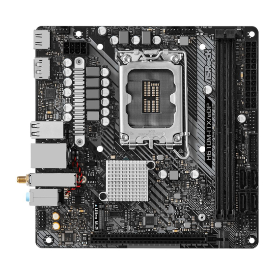
Page 14: Motherboard Layout
1.3 Motherboard Layout Top Side View... - Page 15 H610M-ITX/eDP Back Side View...
- Page 16 No. Description Chassis Fan Connector (CHA_FAN2) ATX 12V Power Connector (ATX12V1) CPU Fan Connector (CPU_FAN1) Chassis/Water Pump Fan Connector (CHA_FAN1/WP) 2 x 288-pin DDR4 DIMM Slots (DDR4_A1, DDR4_B1) ATX Power Connector (ATXPWR1) USB 2.0 Header (USB_5_6) USB 3.2 Gen1 Header (USB32_3_4) SATA3 Connector (SATA3_0) SATA3 Connector (SATA3_1) SATA3 Connector (SATA3_2)
-
Page 17: I/O Panel
H610M-ITX/eDP 1.4 I/O Panel No. Description No. Description LAN RJ-45 Port* USB 3.2 Gen1 Ports (USB32_12) Line In (Light Blue)** USB 2.0 Ports (USB_1234)*** Front Speaker (Lime)** DisplayPort 1.4 Microphone (Pink)** HDMI Port Antenna Ports * There are two LEDs on each LAN port. Please refer to the table below for the LAN port LED indications. -
Page 18: Wifi-802.11Ac Module And Asrock Wifi 2.4/5 Ghz Antennas
1.5 WiFi-802.11ac Module and ASRock WiFi 2.4/5 GHz Antennas WiFi-802.11ac + BT Module This motherboard comes with an exclusive WiFi 802.11 a/b/g/n/ac + BT v5.1 module (pre-installed on the rear I/O panel) that offers support for WiFi 802.11 a/b/ g/n/ac connectivity standards and Bluetooth v5.1. WiFi + BT module is an easy-to- use wireless local area network (WLAN) adapter to support WiFi + BT. - Page 19 H610M-ITX/eDP WiFi Antennas Installation Guide Step 1 Prepare the WiFi 2.4/5 GHz Antennas that come with the package. Step 2 Connect the two WiFi 2.4/5 GHz Antennas to the antenna connectors. Turn the antenna clock- wise until it is securely connected.
-
Page 20: Chapter 2 Installation
Chapter 2 Installation This is a Mini-ITX form factor motherboard. Before you install the motherboard, study the configuration of your chassis to ensure that the motherboard fits into it. Pre-installation Precautions Take note of the following precautions before you install motherboard components or change any motherboard settings. -
Page 21: Installing The Cpu
H610M-ITX/eDP 2.1 Installing the CPU 1. Before you insert the 1700-Pin CPU into the socket, please check if the PnP cap is on the socket, if the CPU surface is unclean, or if there are any bent pins in the socket. - Page 23 H610M-ITX/eDP Please save and replace the cover if the processor is removed. The cover must be placed if you wish to return the motherboard for after service.
-
Page 24: Installing The Cpu Fan And Heatsink
2.2 Installing the CPU Fan and Heatsink... -
Page 25: Installing Memory Modules (Dimm)
H610M-ITX/eDP 2.3 Installing Memory Modules (DIMM) This motherboard provides two 288-pin DDR4 (Double Data Rate 4) DIMM slots, and supports Dual Channel Memory Technology. 1. For dual channel configuration, you always need to install identical (the same brand, speed, size and chip-type) DDR4 DIMM pairs. -
Page 27: Expansion Slots (Pcie Slot)
H610M-ITX/eDP 2.4 Expansion Slots (PCIe Slot) There is 1 PCIe slot on the motherboard. Before installing an expansion card, please make sure that the power supply is switched off or the power cord is unplugged. Please read the documentation of the expansion card and make necessary hardware settings for the card before you start the installation. -
Page 28: Jumpers Setup
2.5 Jumpers Setup The illustration shows how jumpers are setup. When the jumper cap is placed on the pins, the jumper is “Short”. If no jumper cap is placed on the pins, the jumper is “Open”. Clear CMOS Jumper (CLRMOS1) 2-pin Jumper (see p.6, No. -
Page 29: Onboard Headers And Connectors
H610M-ITX/eDP 2.6 Onboard Headers and Connectors Onboard headers and connectors are NOT jumpers. Do NOT place jumper caps over these headers and connectors. Placing jumper caps over the headers and connectors will cause permanent damage to the motherboard. System Panel Header... - Page 30 Serial ATA3 Connectors These four SATA3 (SATA3_0: connectors support SATA see p.6, No. 9) data cables for internal (SATA3_1: storage devices with up to see p.6, No. 10) 6.0 Gb/s data transfer rate. (SATA3_2: * If M2_1 is occupied by see p.6, No.
- Page 31 H610M-ITX/eDP Chassis Speaker Header Please connect the chassis SPEAKER (4-pin SPEAKER1) speaker to this header. DUMMY DUMMY (see p.6, No. 15) Chassis/Water Pump Fan This motherboard 4 3 2 1 Connector provides a 4-Pin water (4-pin CHA_FAN1/WP) cooling chassis fan FAN_SPEED_CONTROL (see p.6, No.
- Page 32 ATX 12V Power This motherboard Connector provides a 8-pin ATX 12V (8-pin ATX12V1) power connector. To use a (see p.6, No. 2) 4-pin ATX power supply, please plug it along Pin 1 and Pin 5. *Warning: Please make sure that the power cable connected is for the CPU and not the graphics card.
- Page 33 H610M-ITX/eDP 2.7 M.2_SSD (NGFF) Module Installation Guide (M2_1) The M.2, also known as the Next Generation Form Factor (NGFF), is a small size and versatile card edge connector that aims to replace mPCIe and mSATA. The Ultra M.2 Socket (M2_1, Key M), supports type 2280 SATA3 6.0 Gb/s & PCIe Gen3x4 (32 Gb/s) modes.
- Page 34 Step 3 Align and gently insert the M.2 (NGFF) SSD module into the M.2 slot. Please be aware that the M.2 (NGFF) SSD module only fits in one orientation. Step 4 Tighten the screw with a screwdriver to secure the module into place. Please do not overtighten the screw as this might damage the module.
- Page 35 H610M-ITX/eDP M.2_SSD (NGFF) Module Support List Vendor Interface ADATA SATA3 AXNS330E-32GM-B ADATA SATA3 AXNS381E-128GM-B ADATA SATA3 AXNS381E-256GM-B ADATA SATA3 ASU800NS38-256GT-C ADATA SATA3 ASU800NS38-512GT-C ADATA PCIe3 x4 ASX7000NP-128GT-C ADATA PCIe3 x4 ASX8000NP-256GM-C ADATA PCIe3 x4 ASX7000NP-256GT-C ADATA PCIe3 x4 ASX8000NP-512GM-C ADATA...
- Page 36 SATA3 VLM100-120G-2280B-RD V-Color SATA3 VLM100-240G-2280RGB V-Color SATA3 VSM100-240G-2280 V-Color SATA3 VLM100-240G-2280B-RD SATA3 WDS100T1B0B-00AS40 SATA3 WDS240G1G0B-00RC30 PCIe3 x4 WDS256G1X0C-00ENX0 (NVME) PCIe3 x4 WDS512G1X0C-00ENX0 (NVME) For the latest updates of M.2_SSD (NFGG) module support list, please visit our website for details: http://www.asrock.com...
-
Page 37: Change Screen Brightness For Edp In Windows
H610M-ITX/eDP 2.8 Change Screen Brightness for eDP in Windows® This section explains how to change screen brightness in Windows® when you use an eDP panel. The following is a setup example for Windows® 11. Setup procedures may vary from different operating systems. - Page 38 Step 3 You might also see another check box displayed: Help improve battery by optimizing the content shown and brightness. Select the check box to turn on the content adaptive brightness control if needed.
-
Page 39: Chapter 3 Software And Utilities Operation
H610M-ITX/eDP Chapter 3 Software and Utilities Operation 3.1 Installing Drivers The Support CD that comes with the motherboard contains necessary drivers and useful utilities that enhance the motherboard’s features. Running The Support CD To begin using the support CD, insert the CD into your CD-ROM drive. The CD automatically displays the Main Menu if “AUTORUN”... -
Page 40: Asrock Motherboard Utility (A-Tuning)
3.2.1 Installing ASRock Motherboard Utility (A-Tuning) ASRock Motherboard Utility (A-Tuning) can be downloaded from ASRock Live Update & APP Shop. After the installation, you will find the icon “ASRock Mother- board Utility (A-Tuning)“ on your desktop. Double-click the “ASRock Motherboard Utility (A-Tuning)“... - Page 41 H610M-ITX/eDP OC Tweaker Configurations for overclocking the system. System Info View information about the system. *The System Browser tab may not appear for certain models.
- Page 42 Settings Configure ASRock ASRock Motherboard Utility (A-Tuning). Click to select "Auto run at Windows Startup" if you want ASRock Motherboard Utility (A-Tuning) to be launched when you start up the Windows operating system.
-
Page 43: Asrock Live Update & App Shop
Double-click on your desktop to access ASRock Live Update & APP Shop utility. *You need to be connected to the Internet to download apps from the ASRock Live Update & APP Shop. 3.3.1 UI Overview Category Panel Hot News... -
Page 44: Apps
3.3.2 Apps When the "Apps" tab is selected, you will see all the available apps on screen for you to download. Installing an App Step 1 Find the app you want to install. The most recommended app appears on the left side of the screen. The other various apps are shown on the right. - Page 45 H610M-ITX/eDP Step 3 If you want to install the app, click on the red icon to start downloading. Step 4 When installation completes, you can find the green "Installed" icon appears on the upper right corner. To uninstall it, simply click on the trash can icon...
- Page 46 Upgrading an App You can only upgrade the apps you have already installed. When there is an available new version for your app, you will find the mark of "New Version" appears below the installed app icon. Step 1 Click on the app icon to see more details. Step 2 Click on the yellow icon to start upgrading.
-
Page 47: Bios & Drivers
H610M-ITX/eDP 3.3.3 BIOS & Drivers Installing BIOS or Drivers When the "BIOS & Drivers" tab is selected, you will see a list of recommended or critical updates for the BIOS or drivers. Please update them all soon. Step 1 Please check the item information before update. Click on to see more details. -
Page 48: Setting
3.3.4 Setting In the "Setting" page, you can change the language, select the server location, and determine if you want to automatically run the ASRock Live Update & APP Shop on Windows startup. -
Page 49: Chapter 4 Uefi Setup Utility
H610M-ITX/eDP Chapter 4 UEFI SETUP UTILITY 4.1 Introduction This section explains how to use the UEFI SETUP UTILITY to configure your system. You may run the UEFI SETUP UTILITY by pressing <F2> or <Del> right after you power on the computer, otherwise, the Power-On-Self-Test (POST) will continue with its test routines. -
Page 50: Ez Mode
4.2 EZ Mode The EZ Mode screen appears when you enter the BIOS setup program by default. EZ mode is a dashboard which contains multiple readings of the system’s current status. You can check the most crucial information of your system, such as CPU speed, DRAM frequency, SATA information, fan speed, etc. -
Page 51: Advanced Mode
H610M-ITX/eDP 4.3 Advanced Mode The Advanced Mode provides more options to configure the BIOS settings. Refer to the following sections for the detailed configurations. To access the EZ Mode, press <F6> or click the "EZ Mode" button at the upper right corner of the screen. -
Page 52: Navigation Keys
4.3.2 Navigation Keys Use < > key or < > key to choose among the selections on the menu bar, and use < > key or < > key to move the cursor up or down to select items, then press <Enter>... -
Page 53: Main Screen
H610M-ITX/eDP 4.4 Main Screen When you enter the UEFI SETUP UTILITY, the Main screen will appear and display the system overview. The availability and location of BIOS settings can be different for different models and BIOS versions. My Favorite Display your collection of BIOS items. Press F5 to add/remove your favorite items. -
Page 54: Oc Tweaker Screen
4.5 OC Tweaker Screen In the OC Tweaker screen, you can set up overclocking features. Because the UEFI software is constantly being updated, the following UEFI setup screens and descriptions are for reference purpose only, and they may not exactly match what you see on your screen. - Page 55 H610M-ITX/eDP The CPU speed is determined by the CPU P-Core Ratio multiplied with the BCLK. Increasing the CPU P-Core Ratio will increase the internal CPU clock speed without affecting the clock speed of other components. AVX2 Ratio Offset AVX2 Ratio Offset specifies a negative offset from the CPU Ratio for AVX workloads.
- Page 56 Intel SpeedStep technology allows processors to switch between multiple frequen- cies and voltage points for better power saving and heat dissipation. Intel Turbo Boost Technology Intel Turbo Boost Technology enables the processor to run above its base operating frequency when the operating system requests the highest performance state. Intel Speed Shift Technology Enable/Disable Intel Speed Shift Technology support.
- Page 57 H610M-ITX/eDP DRAM Timing Configuration DRAM Reference Clock Select Auto for optimized settings. DRAM Frequency If [Auto] is selected, the motherboard will detect the memory module(s) inserted and assign the appropriate frequency automatically. DRAM Gear Mode High gear is good for high frequency.
- Page 58 The number of clocks from a Refresh command until the first Activate command to the same rank. RAS to RAS Delay (tRRD_L) The number of clocks between two rows activated in different banks of the same rank. RAS to RAS Delay (tRRD_S) The number of clocks between two rows activated in different banks of the same rank.
- Page 59 H610M-ITX/eDP Turn Around Timing Turn Around Timing Optimization Auto is enabled in general case. TAT Training Value tRDRD_sg Configure between module read to read delay. tRDRD_dg Configure between module read to read delay. tRDRD_dr Configure between module read to read delay.
- Page 60 Configure between module write to read delay. tWRWR_sg Configure between module write to write delay. tWRWR_dg Configure between module write to write delay. tWRWR_dr Configure between module write to write delay. tWRWR_dd Configure between module write to write delay. TAT Runtime Value tRDRD_sg Configure between module read to read delay.
- Page 61 H610M-ITX/eDP Configure between module write to read delay. tWRRD_dg Configure between module write to read delay. tWRRD_dr Configure between module write to read delay. tWRRD_dd Configure between module write to read delay. tWRWR_sg Configure between module write to write delay.
- Page 62 Configure round trip latency initial value. Initial RTL (MC1 C0 B1) Configure round trip latency initial value. Initial RTL (MC1 C1 B1) Configure round trip latency initial value. RTL (MC0 C0 A1) Configure round trip latency value. RTL (MC0 C1 A1) Configure round trip latency value.
- Page 63 Configure the memory on die termination resistors' PARK for channel B1. Advanced Setting ASRock Timing Optimization Configure the fast path through the MRC. ASRock Second Timing Optimization Configure the second fast path through the MRC. MRC Training Respond Time Try Slowest MRC Training.
- Page 64 Allows users to set VID Step as 5mV or 10mV. DRAM Voltage Use this to configure DRAM Voltage. The default value is [Auto]. VCCIN AUX Voltage Configure the voltage for the VCCIN AUX. +1.8V PROC Voltage Configure the CPU voltage (1.8V). +1.05V PROC Voltage Configure the CPU voltage (1.05V).
- Page 65 H610M-ITX/eDP VF Configuration Scope Allows all cores VF curve or per-core VF curve configuration. Core Voltage Offset Specifies the offset voltage applied to the IA Core domain. This voltage is specified in millivolts. E-Core L2 Voltage Mode Selects between adaptive and Override Voltage modes. In Override Mode the voltage selected will be applied over all operating frequencies.
- Page 66 Selects between adaptive and Override Voltage modes. In Override Mode the voltage selected will be applied over all operating frequencies. In Adaptive Mode the voltage is interpolated only in turbo mode. Uses Mailbox 0SR 0x150, cmd 0x10, 0x11. Extra Turbo Voltage Specifies the extra turbo voltage applied while GT is operating in turbo mode.
-
Page 67: Advanced Screen
H610M-ITX/eDP 4.6 Advanced Screen In this section, you may set the configurations for the following items: CPU Configuration, Chipset Configuration, Storage Configuration, ACPI Configuration, USB Configuration and Trusted Computing. Setting wrong values in this section may cause the system to malfunction. -
Page 68: Cpu Configuration
4.6.1 CPU Configuration Processor P-Core Information This item displays the P-Core Information. Processor E-Core Information This item displays the E-Core Information. Intel Hyper Threading Technology Intel Hyper Threading Technology allows multiple threads to run on each core, so that the overall performance on threaded software is improved. Active Processor P-Cores Select the number of cores to enable in each processor package. - Page 69 H610M-ITX/eDP CPU C6 State Support Enable C6 deep sleep state for lower power consumption. CPU C7 State Support Enable C7 deep sleep state for lower power consumption. Package C State Support Enable CPU, PCIe, Memory, Graphics C State Support for power saving.
-
Page 70: Chipset Configuration
4.6.2 Chipset Configuration Primary Graphics Adapter Select a primary VGA. Above 4G Decoding Enable or disable 64bit capable Devices to be decoded in Above 4G Address Space (only if the system supports 64 bit PCI decoding). C.A.M (Clever Access Memory) If system has Resizable BAR capable PCIe Devices, use this option to enable or disable Resizable BAR support (only of the system supports 64-bit PCI decoding). - Page 71 H610M-ITX/eDP Configure DMI Slot Link Speed. Auto mode is optimizing for overclocking. PCIE1 Link Speed Select the link speed for PCIE1. PCI Express Native Control Select Enable for enhanced PCI Express power saving in OS. PCIE ASPM Support This option enables/disables the ASPM support for all CPU downstream devices.
- Page 72 Select the power state after a power failure. If [Power Off] is selected, the power will remain off when the power recovers. If [Power On] is selected, the system will start to boot up when the power recovers.
-
Page 73: Storage Configuration
H610M-ITX/eDP 4.6.3 Storage Configuration SATA Controller(s) Enable/disable the SATA controllers. SATA Mode Selection AHCI: Supports new features that improve performance. Hybrid Storage Detection and Configuration Mode This item allows you select Hybrid Storage Detection and Configuration Mode. SATA Aggressive Link Power Management SATA Aggressive Link Power Management allows SATA devices to enter a low power state during periods of inactivity to save power. -
Page 74: Acpi Configuration
4.6.4 ACPI Configuration Suspend to RAM Select disable for ACPI suspend type S1. It is recommended to select auto for ACPI S3 power saving. PCIE Devices Power On Allow the system to be waked up by a PCIE device and enable wake on LAN. I219 LAN Power On Allow the system to be waked up by the Onboard Intel LAN. -
Page 75: Usb Configuration
H610M-ITX/eDP 4.6.5 USB Configuration XHCI Hand-off This is a workaround for OSes without XHCI hand-off support. The XHCI ownership change should be claimed by XHCI driver. -
Page 76: Trusted Computing
4.6.6 Trusted Computing NOTE: Options vary depending on the version of your connected TPM module. Security Device Support Use this item to enable or disable BIOS support for security device. O.S. will not show Security Device. TCG EFI protocol and INT1A interface will not be available. Active PCR banks This item displays active PCR Banks. - Page 77 H610M-ITX/eDP NOTE: Your computer will reboot during restart in order to change State of the Device. Platform Hierarchy Use this item to enable or disable Platform Hierarchy. Storage Hierarchy Use this item to enable or disable Storage Hierarchy. Endorsement Hierarchy Use this item to enable or disable Endorsement Hierarchy.
-
Page 78: Tools
4.7 Tools UEFI Tech Service Contact ASRock Tech Service if you are having trouble with your PC. Please setup network configuration before using UEFI Tech Service. SSD Secure Erase Tool All the SSD's listed that supports Secure Erase function. NVME Sanitization Tool After you Sanitize SSD, all user data will be permanently destroyed on the SSD and cannot be recovered. - Page 79 H610M-ITX/eDP Network Configuration Use this to configure internet connection settings for Internet Flash. Internet Setting Enable or disable sound effects in the setup utility. UEFI Download Server Select a server to download the UEFI firmware.
-
Page 80: Hardware Health Event Monitoring Screen
4.8 Hardware Health Event Monitoring Screen This section allows you to monitor the status of the hardware on your system, including the parameters of the CPU temperature, motherboard temperature, fan speed and voltage. Fan Tuning Measure Fan Min Duty Cycle. Fan-Tastic Tuning Select a fan mode for CPU Fan, or choose Customize to set 5 CPU temperatures and assign a respective fan speed for each temperature. - Page 81 H610M-ITX/eDP Chassis Fan 1 Control Mode Select PWM mode or DC mode for Chassis Fan 1. Chassis Fan 1 Setting Select a fan mode for Chassis Fan 1, or choose Customize to set 5 CPU temperatures and assign a respective fan speed for each temperature.
-
Page 82: Security Screen
4.9 Security Screen In this section you may set or change the supervisor/user password for the system. You may also clear the user password. Supervisor Password Set or change the password for the administrator account. Only the administrator has authority to change the settings in the UEFI Setup Utility. Leave it blank and press enter to remove the password. -
Page 83: Boot Screen
H610M-ITX/eDP 4.10 Boot Screen This section displays the available devices on your system for you to configure the boot settings and the boot priority. Fast Boot Fast Boot minimizes your computer's boot time. In fast mode you may not boot from an USB storage device. - Page 84 Full Screen Logo Enable to display the boot logo or disable to show normal POST messages. AddOn ROM Display Enable AddOn ROM Display to see the AddOn ROM messages or configure the AddOn ROM if you've enabled Full Screen Logo. Disable for faster boot speed. Boot Failure Guard Message If the computer fails to boot for a number of times the system automatically restores the default settings.
- Page 85 H610M-ITX/eDP only to run those that support legacy option ROM only. Select Do not launch to not execute both legacy and UEFI option ROM. Other PCI Device ROM Priority For PCI devices other than Network. Mass storage or Video defines which OpROM...
-
Page 86: Exit Screen
4.11 Exit Screen Save Changes and Exit When you select this option the following message, “Save configuration changes and exit setup?” will pop out. Select [OK] to save changes and exit the UEFI SETUP UTILITY. Discard Changes and Exit When you select this option the following message, “Discard changes and exit setup?”... - Page 87 Contact Information If you need to contact ASRock or want to know more about ASRock, you’re welcome to visit ASRock’s website at http://www.asrock.com; or you may contact your dealer for further information. For technical questions, please submit a support request form at https://event.asrock.com/tsd.asp...
Need help?
Do you have a question about the H610M-ITX/eDP and is the answer not in the manual?
Questions and answers