Advertisement
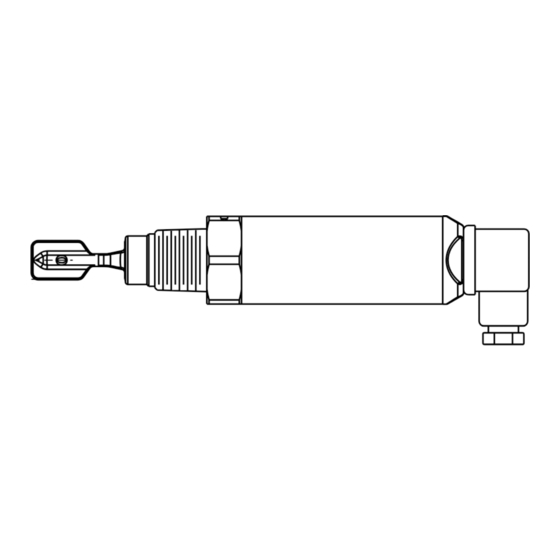
SC28P/N Mini Tuning Fork Level Switch
Operation Manual
WIRING
Power supply is DC. Output is PNP / NPN.
Please see Figure 1.
►DIN & Cable Wiring
PNP Output:
High(Max.) Mode: No. 1 pin(Brown) is connected to N-.
No.3 pin(Blue) is connected to L+. Output is connected
to No. 2 pin(Black), then connected to N-. No. 4
pin(Yellow Green) goes to ground.
Low(Min.)Mode: number 1 pin(Brown) is connected to
N-. No.2 pin(Black) is connected to L+.
Output is connected to No. 3 pin(Blue), then connected
to N-. No. 4 pin(Yellow Green) goes to ground.
NPN Output:
High(Max.) Mode: No. 1 pin(Brown) is connected to L+.
No.3 pin(Blue) is connected to N-. Output is connected
to No. 2 pin(Black), then connected to L+. No. 4
pin(Yellow Green) goes to ground.
Low(Min.)Mode: No. 1 pin(Brown) is connected to N-.
No.3 pin (Blue) is connected to L+. Output is connected
to No.2 pin (Black), then connected to L+. No. 4
pin(Yellow Green) goes to ground.
►M12 x 4Pin Wiring:
PNP Output
High(Max.) Mode: No. 1 pin(Brown) is connected to L+.
No.3 pin(Blue) is connected to N-. Output is connected
to No. 2 pin White(Green), then connected to N-.
Low(Min.) Mode: number 1 pin(Brown) is connected to
L+. No.3 pin(Blue) is connected to N-. Output is
connected to No. 4 pin(Black), then connected to N–.
NPN Output
High(Max.) Mode: No. 1 pin(Brown) is connected to L+.
No.3 pin(Blue) is connected to N-. Output is connected
to No. 2 pin White(Green), then connected to L+.
Low(Min.) Mode: No. 1 pin(Brown) is connected to L+.
No.3 pin(Blue) is connectsed to N-. Output is connected
to No. 4 pin(Black), then connected to L+.
DIN Cable Wiring Diagram
PNP
Max.
Min.
Yellow
Yellow
Green
Green
Black
Brown
Brown
Black
1 2
1 2
3
3
Blue
Blue
Load
Load
Fuse
Fuse
0.5A
0.5A
PE
N-
L+
PE
N-
L+
NPN
Min.
Max.
Yellow
Yellow
Green
Green
Brown
Black
Brown
Black
1 2
1 2
3
3
Blue
Blue
Load
Load
Fuse
Fuse
0.5A
0.5A
PE L+ N-
PE
N-
L+
M12x4Pin Wiring Diagram
PNP
Min.
Max.
Load
Black
Black
Blue
Blue
Brown
Brown
Load
White(Green)
White(Green)
Fuse
Fuse
0.5A
0.5A
L+ N-
L+ N-
M12-4Pin
M12-4Pin
NPN
Min.
Max.
Load
Black
Black
Blue
Blue
Brown
Brown
White(Green)
Load
White(Green)
Fuse
Fuse
0.5A
0.5A
L+ N-
L+ N-
M12-4Pin
M12-4Pin
M12 Connector
Connection
wire color
PIN
1
Power supply +
Brown
2
OUT2
White(Green)
3
Power supply -
Blue
OUT1/
4
Black
communication interface
SC28P/N fork sensing spot is shown as Figure 2 below. Considering
3
testing medium is water(S.G.=1 g/cm ), sensing spot is at the fillister about
12mm from the tip. If testing medium has S.G. lower than 1g/cm , sensing
spot would be above the fillister. In contrast, sensing spot will be below
the fillister.
3
S.G.<1g/cm
Sensing spot
moves upward
Sensing spot
8mm
3
S.G.>1g/cm
Sensing spot
moves downward
Figure 2 Fork Sensing Spot
MAGNETIC TEST
After the switch is installed and powered, magnetic test function
can be performed accordingly please see Figure 3. The testing
point is marked on the housing label. User holds the magnet
and moves it close to testing point, the output status will switch
from NO. to NC. or NC to NO. and red LED would switch ON
or OFF while fork continues to vibrate.
When magnet is pulled away from the testing point, the output
status and red LED would return as default while fork continues
to vibrate. The purpose of testing is to confirm the wiring and
functioning are correct.
3
3
S.G.<1g/cm
Sensing spot
moves upward
Sensing
12mm
spot
3
S.G.>1g/cm
Sensing spot
moves downward
Magnet
Figure 3 Magnetic Test Diagram
Advertisement
Table of Contents

Summary of Contents for FineTek SC28P/N
- Page 1 DIN Cable Wiring Diagram Power supply is DC. Output is PNP / NPN. SC28P/N fork sensing spot is shown as Figure 2 below. Considering Please see Figure 1. testing medium is water(S.G.=1 g/cm ), sensing spot is at the fillister about Max.
- Page 2 OUTPUT STATUS Horizontal Installation: Vertical Installation: SC28P/N When powered with 12~55 Vdc, top of housing would light up with green LED. 1. Do not install near substance inlet. DIN & Cable type 1. Opening of the two fork blades is to be as the flow direction.


Need help?
Do you have a question about the SC28P/N and is the answer not in the manual?
Questions and answers