Advertisement
Quick Links
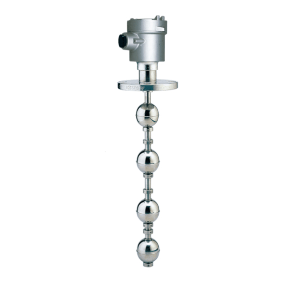
FD7 Series Explosion Type Magnetic Float
Level Switch Operation Manual
APPLICABLE MODEL:FD7 Series
PRINCIPLE
The single unit or multiple reed switch units are housed tightly in stainless steel stem and
tount the float ball to penetrate through the stem, then the liquid buoyancy will deliver the float
up and down at the specified position by graduating rings. When the reed switch is induction
the float internal magnet, then it will actuate the reed switch contact point to create an open or
close circuit. We can apply such on-off output signal to reach liquid level controlling and
monitoring purpose. The permanent magnet is interlined into the middle of the specified float
balls. You Can mhe figures below show the float orientations on N.O. (Normal Open) and N.C.
(Normal Close).
SPECIFICATION
1.Pressure Rating : Max. pressure of plastic floats is 5kg/cm and max. pressure of
SUS floats is 35kg/cm (S10 floats can reach 50kg/cm )
2.Lead Wire : XLPE (UL3266, AWG22)
SPECIFICATION
Switching
Tube Type
Material
Capacity Max.
Contact from
OD8
SUS
SPST
SPST
OD9.5
SUS
SPDT
SPST
OD12.7
SUS
SPDT
INDUCTIVE / CAPACITIVE LOADS
1.Inductive : When using a reed switch with inductive loads such as motors,
relays,solenoids..etc, the contact will be subjected to a high induced voltage
during opening of the contact(load circuit). Such high induced
voltage(transients) may cause damages to the reed switch or significantly
reduce it life. Therefore,protective circuits such as : RC(snubber), varistors or
clamping diodes are recommended.
2.Capacitive : When using a reed switch with capacitive loads such as
capacitors,incandescent lamps or long cables, the contact will be subjected
to a high surge(inrush) current. Therefore, protective circuits such as:
surgesuppressors or current limiting resistors are recommended.
2
2
Switching
Switching
Switching
Voltage Max.
Current Max.
50W
300Vac/350Vdc
0.5A
50W
300Vac/350Vdc
0.5A
20W
150Vac/200Vdc
1A
50W
220Vac/500Vdc
3A
50W
400Vac/1000Vdc
1A
CONNECTION INFORMATION
1) Open the cap of housing, connect the wire onto terminal through the conduit.
2) Check the terminal wire connection is correct for each float.
3) Connection Type : Please refer to Fig.1 below.
A) 1NO : Meaning that the NO-C circuit will be close while liquid level higher than the float
B) 1NC : Meaning that the B-C circuit will be close while liquid level lower than the float ball
C) 1C : Meaning that the NO-C circuit will be close while liquid level higher than
4) Please screw up the housing cap and fix the conduit outlet to prevent the moisture to
2
soak in.
WIRING
Carry
Current Max.
1NO 1C 1NC
2.5A
2.5A
2A
4A
2NO 2C 2NC
2A
3NO 3C 3NC
4NO 4C 4NC
5NO 5C 5NC
NEPSI Ex d IIC T3~T6 Gb
ATEX
ATEX
II 2 G Ex d IIB T3 or T4 or T5 or T6 Gb
II 2 D Ex tb IIIC T200BC or T135BC or T100BC or T85BC Db
IECEx Ex db IIB T3 or T4 or T5 or T6 Gb
Ex tb IIIC T200BC or T135BC or T100BC or T85BC Db
ball by mark of " ON".
by mark of " ON".
the float ball and NC-C circuit will be close while liquid level lower than
the float ball.
1NO 1C 1NC
1NO 1C 1NC
2NO 2C 2NC
2NO 2C 2NC
3NO 3C 3NC
3NO 3C 3NC
4NO 4C 4NC
4NO 4C 4NC
5NC
5NO 5C
5NO 5C 5NC
(Fig.1)
1
2
3
4
5
Advertisement

Related Manuals for FineTek FD7 Series


Summary of Contents for FineTek FD7 Series
- Page 1 NEPSI Ex d IIC T3~T6 Gb FD7 Series Explosion Type Magnetic Float ATEX ATEX II 2 G Ex d IIB T3 or T4 or T5 or T6 Gb II 2 D Ex tb IIIC T200BC or T135BC or T100BC or T85BC Db...
- Page 2 INSTALLATION TROUBLE SHOOTING The float level switch should be mounted far There better be an L type supporter, when the Trouble Pussible cause Solution away from liquid inlet, any strong liquid switch is mounted in concrete wall tank as fluctuation will produce error output signals. figure below.
Need help?
Do you have a question about the FD7 Series and is the answer not in the manual?
Questions and answers