Table of Contents
Advertisement
Quick Links
Advertisement
Table of Contents

Related Manuals for Custom Audio Electronics F 190


Summary of Contents for Custom Audio Electronics F 190
- Page 1 F 190 Panel printer User’s manual www.custom.it F 190...
- Page 2 COD. DOME-F190 Revision 1.20 Copyright © 1998 Custom Engineering s.r.l. – Italy Custom Engineering Str. Berettine 2 - 43010 Fontevivo (PARMA) - Italy Tel. : +39 0521-680111 Fax : +39 0521-610701 http: www.custom.it Email : support@custom.it F 190...
- Page 3 D. The printer is not operating normally despite the instructions in the user’s manual having been followed. E. The printer has been dropped and its case damaged. F. The performance of the printer is poor. G. The printer does not work. F 190...
-
Page 4: Table Of Contents
3.1 TTL serial 3.2 TTL parallel 3.3 Real Time Clock (option) 4. PRINTER FUNCTIONS 4.1 Printing modes 4.2 Graphics 4.3 Control characters 4.4 Character sets APPENDIX CONTENTS A. POWER SUPPLIES A.1 PSM05 power supply A.2 ALI 9/40 power supply F 190... -
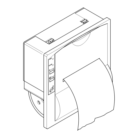
Page 5: Description
It has a 150 byte print buffer and, is equipped with a 2-Kbyte EEPROM. It has TTL serial and parallel interfaces as standard. It can, in addition, be equipped with a Real Time Clock. (Figure 1) F 190... -
Page 6: Product Description
FEED key. This enables the manual paper feed. If pressed briefly, when the RTCK option is installed, the time and date are printed. The POWER LED indicates that digital power is being supplied to the printer. The STATUS LED, when lit, signals that the paper is finished or that the cover is open. F 190... -
Page 7: Technical Specifications
Medium when printing 880 mA 3,5 A (600 µSec) Impulse when printing Environmental conditions Operating temperature 0°C - +50°C Operating humidity 35% - 85% Storage temperature /humidity -20°C - +70°C / 10%-90% Options Real time clock, Power supply F 190... -
Page 8: Installation And Use
For the pin pattern required for supplying power through the logic flat cable, please refer to the following paragraph. Logic In the J2 20-pin connector, the signals are arranged as follows: +VDC +VDC RESET S-EN READY/RTS FEED STB/RD F 190... - Page 9 1: in order to obtain logic level 0, it has to be shortcircuited to ground (GND). The serial baud rate can be selected from the following table: F 190...
- Page 10 S-EN pin of J1 for serial or parallel configuration; printing of the self-test if the FEED key is pressed; functionality check of the option cards installed, if any. F 190...
-
Page 11: Configuration
This can be done by using an IBM or IBM-compatible computer with a serial output, or else by using a programme which can be supplied on request. This programme, with its pull-down menus is user- friendly and prompts the operator at each stage of the input procedure. F 190... -
Page 12: Self-Test
Do not pull the printer carriage manually when the printer is ON. Before connecting the printer to the mains, check that the power supply or system ON/OFF switch is in the OFF position. Avoid blows to any part of the printer, both during and after installation. F 190... -
Page 13: Maintenance
3) press the FEED key so that a few centimetres of paper come out of the printer and, pressing down again on the swinging support of the print mechanism marked with the instruction PUSH, bring it back to its original position. 4) tear off the paper and re-close the printer cover. (Figure 3) F 190... -
Page 14: Interfaces
In the serial protocol, the signals which characterize communication are TD, RD and RTS if the RTS/CTS protocol has been selected; alternatively, if the XON/OFF protocol has been selected, the signals are TD and RD. Transmission format RTS/CTS protocol dato = data attesa = standby XON/OFF protocol dato = data attesa = standby F 190... -
Page 15: Ttl Parallel
In parallel communication the useable signals are: 1) 7 or 8 bit data bus; 2) STROBE signal indicating data validity; 3) READY signal indicating that the printer is ready to receive data. Transmission format valid data Flow diagram F 190... -
Page 16: Real Time Clock (Option)
For more information on the control characters which manage the clock, see paragraph 4.3. By means of this function (option available with the 5.3 software release) implemented in the Real Time Clock, the total operating hours of the printer can be memorized. F 190... -
Page 17: Printer Functions
1.7 x 5.2 1.1 x 5.2 Double width 3.4 x 2.6 2.2 x 2.6 Expanded 3.4 x 5.2 2.2 x 5.2 For further details on the selection of printing modes, please refer to the paragraph covering control characters (paragraph 4.3). F 190... -
Page 18: Graphics
P6 P5 P4 P3 P2 P1 P6 P5 P4 P3 P2 P1 P6 P5 P4 P3 P2 P1 To print a line of dots transmit: $11, N x $7F (where N is the number of characters per line), $OD. To print an empty line, transmit: $11, $40, $OD. F 190... -
Page 19: Control Characters
Enters time in print buffer ESC U $1B $55 Enters date (mm :dd :yy) in print buffer ESC S $1B $53 Enables printing of seconds ESC O $1B $4F Transmits operating hours in serial ESC H $1B $48 Zero-sets total operating hours F 190... - Page 20 6 dots wide and 10 dots tall. The ASCII characters which can be printed, as may be seen from the self-test, start from code $1E through to code $FF (software release 4.3) or from code $17 to code $1F (software release 5.3). F 190...
- Page 21 20 dots tall. The ASCII characters which can be printed, as may be seen from the self-test, start from code $1E through to code $FF (software release 4.3) or from code $17 to code $1F (software release 5.3). F 190...
- Page 22 CRLF option is contained in the flag of a byte called “option register” which can be manipulated through the configuration by using the two keys on the front panel of the printer or through the programme from the PC. F 190...
- Page 23 If the expanded or double width formats are selected (i.e. with less than 15 characters per line), only the time will be printed. If seconds printing is enabled, the format will be: hh:mm:ss dd - mm - yy In any event this command resets the line. F 190...
- Page 24 If the printer is new (or if the characters have not been manipulated), the following symbol :|||; will be associated with codes $1E and $1F; each time the printer is switched on, the above mentioned codes will contain the last characters programmed in the non volatile memory. F 190...
- Page 25 The reset command can be useful when the system is switched on in order to avoid false characters, which would corrupt the printer’s receiving buffer, from being sent during the master device’s initializing phases. F 190...
- Page 26 If you only wish to print the date, it is enough to transmit $1B$55$0D. The date is transmitted in 8 characters and, if the seconds option is enabled in 8 characters; if there is not sufficient space left in the line buffer, it is not printed. F 190...
- Page 27 If, for example, you wish to write: TOTAL HOURS: 0123 TEST OK you will send: TOTAL HOURS: $1B$6F TEST OK The hours are printed in four characters and if there is not enough space in the line buffer, they will not be printed. F 190...
- Page 28 A 5 or $ 41 $35 The entire memory bank contains the value $20 by default. Since it is a non volatile memory, the user can save the data without losing it when the power is switched off. F 190...
- Page 29 A logic state 0 selects font 1, while a logic state 1 selects font 2. · d7: this bit has no effect on the working of the printer for software release 4.3. From software release 5.3 on, 0 disables the lapsed time meter while 1 enables it. F 190...
- Page 30 Obviously if the printer is using the parallel protocol, the command will produce no effect. Hex: The reply to this question is made in two ASCII bytes containing the option register value. $1B $70 If, for example, we receive: 0 9 (or $30 $39) this means that the configuration will be 00001001. F 190...
- Page 31 The three blocks can also be printed one after the other, there being a total memory bank of 1700 bytes. To recall a block, you must enter the command “ESC” V and the number of the block you wish to recall. F 190...
- Page 32 P6 P5 P4 P3 P2 P1 6° byte P6 P5 P4 P3 P2 P1 7° byte P6 P5 P4 P3 P2 P1 8° byte P6 P5 P4 P3 P2 P1 9° byte P6 P5 P4 P3 P2 P1 10° byte. F 190...
-
Page 33: Character Sets
The printer has two sets, each containing 224 characters (font 1 and font 2), which can be called up from the programme configuration (paragraph 2.4) or through the control characters (paragraph 4.3). (Figure 5) FONT 1 FONT 2 F 190... -
Page 34: Psm05 Power Supply
The following figure shows the model PSM05 power supply, manufactured by Custom Engineering, that can be used to operate the F190 printer. ssis GND cha LED on 0V 5V a t l a t l i n i t i u F 190... -
Page 35: Ali 9/40 Power Supply
The diagram below shows the layout of the ALI 9/40 power supply card, which supplies the printer with an available voltage ranging from 9 to 40 Vdc, through connector J1. The card is fitted directly onto the printer interface card, by means of connector J2. F 190...
Need help?
Do you have a question about the F 190 and is the answer not in the manual?
Questions and answers