Table of Contents
Advertisement
Quick Links
Advertisement
Table of Contents

Subscribe to Our Youtube Channel
Related Manuals for Custom Audio Electronics FT190 II


Summary of Contents for Custom Audio Electronics FT190 II
- Page 1 FT190 II FT190 II USER MANUAL...
- Page 2 All rights reserved. Total or partial reproduction of this manual in whatever form, whether by printed or electronic means, is forbidden. While guaranteeing that the information contained in it has been carefully checked, CUSTOM ENGINEERING SPA and other entities utilized in the realization of this manual bear no responsibility for how the manual is used.
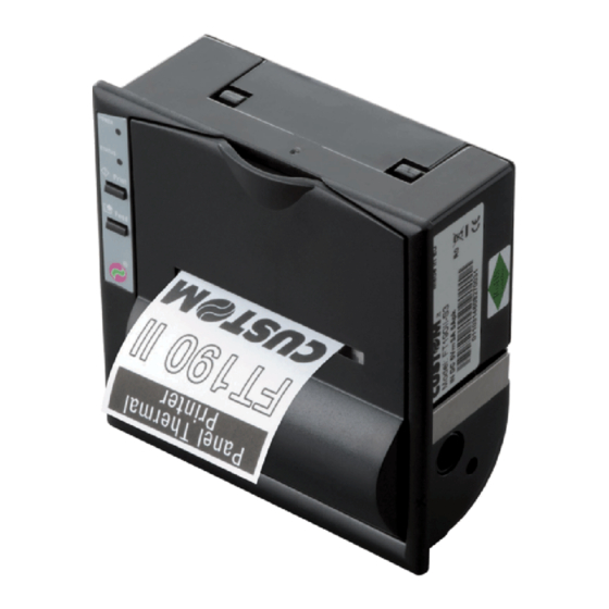
- Page 3 PRINTER COMPONENTS A. FT190 II - Front external view 1- Printing mechanism 2- Case 3- Paper output 4- Paper loading label 5- Front panel 6- Paper roll compartment 7- Control panel POWER STATUS Print Feed FT190 II 3 User Manual...
- Page 4 B. FT190 II - Rear external view 1- Power supply connector 2- Paper winder connector 3- Interface connector 4- External “Print” key connector 4 FT190 II User Manual...
-
Page 5: Table Of Contents
6. CHARACTER SETS 6.1 CHARACTER SETS ..........................6-1 APPENDIX A - ACCESSORIES AND SPARE PARTS A.1 ACCESSORIES ............................. A-1 A.1.1 Power supply ..........................A-1 A.1.2 Paper winder ..........................A-2 A.2 SPARE PARTS............................A-2 A.2.1 Supplies ............................A-2 FT190 II i User Manual... - Page 6 TABLE OF CONTENTS Blank page ii FT190 II User Manual...
-
Page 7: Introduction
The printer is not functioning normally despite the fact that all instructions in the users manual have been followed; The printer has been dropped and its outer casing damaged; Printer performance is poor; The printer is not functioning. FT190 II 1-1 User Manual... -
Page 8: Unpacking The Printer
It is supplied with two interfaces: an RS232 serial and Centronics parallel interface. To select one or the other interface, some jumpers must be moved. The reception buffer is 1Kbytes. It can also be equip- ped with a Real Time Clock. 1-2 FT190 II User Manual... -
Page 9: Printer Description
• The STATUS LED When fl ashing, signals that the paper is fi nished. When lit steadily, it signals the presence of an error (head power supply too high or too low or head temperature too high). FT190 II 1-3 User Manual... - Page 10 1. INTRODUCTION Blank page 1-4 FT190 II User Manual...
-
Page 11: Installation And Use
(Head power supply) + VCC: 5 Vdc ± 7% (Logic power supply) (Tab. 2.1) 9-40V VERSION SIGNAL NOTES Ground signal Ground signal from 9 Vdc to 40 Vdc (Head power supply) N.C. Not connected (Tab. 2.2) FT190 II 2-1 User Manual... -
Page 12: Paper Winder
(Tab. 2.3) 2.1.3 External Print key An external print key may be connected to connector J6 (fi g. 2.1). The polarity and function of the signals are given in Table 2.4. SIGNAL PRINT (Tab. 2.4) 2-2 FT190 II User Manual... -
Page 13: Configuration
Using two-colour thermal paper is possible to set different red tonality. Note The settings made are saved on the EEPROM (non volatile memory). FT190 II 2-3 User Manual... -
Page 14: Autotest
The paper is automatically pulled by the roller for 3 or 4 centimetres; Tear off the paper and re-close the cover. (Fig.2.2) WARNING Make sure the paper edge is straight before inserting it in the machine. 2-4 FT190 II User Manual... -
Page 15: Interfaces
When the DTR/DSR command is selected, this signal in- dicates when the printer is busy. SPACE indicates that the Output printer is ready to receive data and MARK that the printer is busy. Ground Ground Ground (Tab. 3.1) FT190 II 3-1 User Manual... - Page 16 3. INTERFACES The diagrams below give sample connections between the printer and Personal Computer using a 25- and 9-pin female connector. (Fig.3.2) SIGNAL GND PRINTER (Fig.3.3) PRINTER 3-2 FT190 II User Manual...
-
Page 17: Centronics Parallel
Data bit 3 Input Data bit 4 Input Data bit 5 Input Data bit 6 Input Data bit 7 Input Output BUSY Output PAPER END Output HIGHT Output N.C. FALT Output RESET Input 17-25 (Tab. 3.2) FT190 II 3-3 User Manual... -
Page 18: Calendar Clock (Optional)
To proceed to modify another digit, press the FEED key again. Each time the printer will print the upda- ted time and date, highlighting with an arrow the currently selected digit; • To terminate the setting procedure, press PRINT and FEED at the same time. 3-4 FT190 II User Manual... -
Page 19: Printer Functions
4. PRINTER FUNCTIONS 4.1 PRINT DIRECTION The printer has two printing directions wich can be selected by means of the control characters: normal and reverse. FT190II Panel printer (Fig.4.1) Normal mode Reverse mode FT190 II 4-1 User Manual... -
Page 20: Command Descriptions
Enter date (mm :dd :yy) in print buffer $1B $58 ESC X Prints in red $1B $78 ESC x Prints in black $1B $42 ESC B Sets character font 1 $1B $62 ESC b Sets character font 2 4-2 FT190 II User Manual... -
Page 21: Command Description Preliminary Remark
[Example] LEGEND indicates the representation of the command hexadecimal value (for example $40 means HEX 40). indicates an ASCII character not performable. n, m, t, x, y are optional parameters that can have different values. FT190 II 4-3 User Manual... - Page 22 • The commands $00-$09 do not cancel the print buffer • the commands which modify the dimensions of the characters are only active at the beginning of the line [Default] Impostazione nell’option register tramite i tasti frontali [Reference] $00, $01, $02, $04 [Example] 4-4 FT190 II User Manual...
- Page 23 • If the line buffer is empty, the command is ignored. • If the CRLF option is set, this command is ignored and printing can only be ordered through the command $0A. [Default] [Reference] [Example] FT190 II 4-5 User Manual...
- Page 24 - mm - yy • If seconds printing is enabled, the format will be: hh : mm : ss dd - mm - yy [Notes] • The command resets the line. [Default] [Reference] $13, $14 [Example] 4-6 FT190 II User Manual...
- Page 25 Print 1st (...8th) programmable character [Format] ASCII 17,... Decimal 23,... [Range] [Description] This command prints the corresponding programmable character. [Notes] [Default] BITMAP contained in fl ash [Reference] $17, $18, $19, $1A, $1C, $1D, $1E, $1F [Example] FT190 II 4-7 User Manual...
- Page 26 Select normal mode printing:the receipt feeds out of the printer with the printing upside down running from right to left. [Notes] [Default] Setting in option register by means of front keys [Reference] $1B $52 [Example] 4-8 FT190 II User Manual...
- Page 27 Enter in the buffer the date on the calendar clock installed inside the printer, American style: mm-dd-yy [Notes] • The date is printed in 8 characters: if there is not enough space in the buffer, it will not be printed FT190 II 4-9 User Manual...
- Page 28 Selects the second character font. [Notes] • The complete font is printed during the autotest. The font contains cyrillic characters. [Default] Setting in the option register by means of the front keys [Reference] $1B $42 [Example] 4-10 FT190 II User Manual...
- Page 29 The whole memory bank contains the value $20 by default [Reference] $1B $77 [Example] To read address $01, transmit in ASCII: $30 $31 $1B $72 If address $01 contains $A5, we will receive: $41 $35 FT190 II 4-11 User Manual...
- Page 30 • The setting is memorized in the EEPROM and assumed as the default value the next time the printer is switched on [Default] [Reference] $1B $4B [Example] To send setting byte 00001001 ($09): $30 $39 $1B $47 4-12 FT190 II User Manual...
- Page 31 • If the printer is using the parallel protocol, nothing with be transmitted [Default] [Reference] $1B $47, $1B $4B, $1B $6B [Example] The response is on two bytes. E.g., if you receive: $30 $39 it means that the default confi guration is 00001001 FT190 II 4-13 User Manual...
- Page 32 Selects the number of dot spaces [Format] ASCII Decimale [Range] [Description] (dd) are two ASCII characters which identify a hexadecimal byte and correspond to the number of dot lines between one print line and another [Notes] [Default] [Reference] [Example] 4-14 FT190 II User Manual...
- Page 33 After receiving this command, the printer waits for 48 bytes which correspond to an entire graphic line. In fact, 48 bytes of 8 bits each correspond to 384 dots per line. [Notes] [Default] [Reference] [Example] FT190 II 4-15 User Manual...
- Page 34 After this command has been received, the characters are printed underlined. [Notes] [Default] [Reference] $1B $71 [Example] $1B $71 [Name] Disables underlined printing [Format] ASCII Decimal [Range] [Description] Annuls underlined printing [Notes] [Default] [Reference] $1B $51 [Example] 4-16 FT190 II User Manual...
- Page 35 4. PRINTER FUNCTIONS Blank page FT190 II 4-17 User Manual...
-
Page 36: Technical Specifications
Storage temperature / Humidity -25 °C – +70 °C / 10% - 90% Real time clock Options 9 - 40 Vcc Power supply NOTE: Referred to a standard CUSTOM receipt (L=10cm, Density = 12,5% dots on). FT190 II 5-1 User Manual... -
Page 37: Dimensions
5 mm; using the two additional screws provided, the printer can be mounted on panels with a maximum thickness of 15 mm. For even thicker panels, use longer M3 screws. (Fig.5.1) 5-2 FT190 II User Manual... -
Page 38: Character Sets
The printer has two characters sets, each containing 224 characters (font 1 and font 2), which can be called up through the programming (paragraph 2.2) or through the control characters (paragraph 4.2). FONT 1 FONT 2 (Fig.6.1) (Fig.6.2) FT190 II 6-1 User Manual... - Page 39 6. CHARACTER SETS Blank page 6-2 FT190 II User Manual...
-
Page 40: Appendix A - Accessories And Spare Parts
5.0 A PPSPS-025-12 Output specifi cations (for 9-40 VDC version) Output voltage 12 V Output current Maximum 2.1 A PPSPS-025-24 Output specifi cations (for 9-40 VDC version) Output voltage 24 V Output current Maximum 1.1 A FT190 II A-1 User Manual... -
Page 41: Paper Winder
APPENDIX A - ACCESSORIES AND SPARE PARTS A.1.2 Paper winder The AV05 model paper winder can be connected to the printer at the J5 connector. (Fig. A.2) A.2 SPARE PARTS A.2.1 Supplies RCT57X50 57mm Thermal paper roll core 13mm Ø 50 A-2 FT190 II User Manual... - Page 42 APPENDIX A - ACCESSORIES AND SPARE PARTS Blank page FT190 II A-3 User Manual...
- Page 44 CUSTOM ENGINEERING SPA World Headquarters Via Berettine, 2 - 43100 Fontevivo Tel. +39 0521 680111 - Fax +39 0521 610701 info@custom.biz - www.custom.biz All rigths reserved www.custom.biz...
Need help?
Do you have a question about the FT190 II and is the answer not in the manual?
Questions and answers