
Subscribe to Our Youtube Channel
Related Manuals for ACS ACR40T


Summary of Contents for ACS ACR40T
- Page 1 ACR40T USB SIM-sized Smart Card Reader Reference Manual V1.01 Subject to change without prior notice info@acs.com.hk www.acs.com.hk...
- Page 2 Revision History Date Revision Description Version Number ● 2022-11-14 Initial version 1.00 ● 2023-07-26 Document formatting 1.01 Page 2 of 46 www.acs.com ACR40T – Reference Manual info@acs.com.hk www.acs.com.hk Version 1.01...
-
Page 3: Table Of Contents
Endpoints ..........................8 5.0. User Interface ......................9 5.1. Status LED ..........................9 5.2. Configurable push button (ACR40T-A7/8 only) ..............9 6.0. Smart Card Interface ..................... 10 6.1. Smart Card Power Supply VCC (C1) .................. 10 6.2. Programming Voltage VPP (C6) ..................10 6.3. - Page 4 List of Figures Figure 1 : ACR40T Architecture ......................7 List of Tables Table 1 : Symbols and Abbreviations ..................... 5 Table 2 : USB Interface Wiring ....................... 8 Table 3 : Status LED ..........................9 Table 4 : Operation mode of button ......................9 Page 4 of 46 www.acs.com...
-
Page 5: Introduction
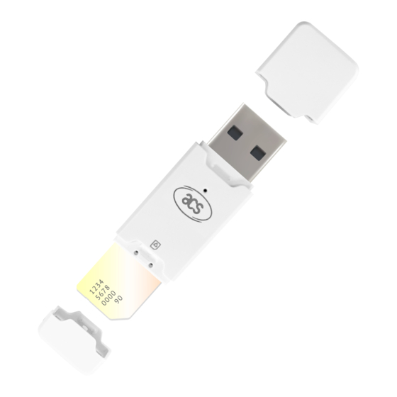
1.0. Introduction The ACR40T USB Sim-sized smart card reader serves as an intermediary for communication between a computer and a smart card. Different smart cards have varying communication protocols and commands, making direct communication with a computer challenging. However, the ACR40T USB Sim-sized smart card reader offers a standardized interface for a broad range of smart cards, thus freeing software developers from the technical complexities of smart card operations. -
Page 6: Smart Card Support
2.1. MCU Cards ACR40T is a PC/SC-compliant smart card reader that supports ISO 7816 Class A, B, and C (5 V, 3 V, and 1.8 V) smart cards. It also works with MCU cards following either the T=0 and T=1 protocol. -
Page 7: System Block Diagram
3.0. System Block Diagram ACR40T SIM-sized LEDs Button* Card Computer Figure 1: ACR40T Architecture *Button is only available in model ACR40T-A7/8 Page 7 of 46 www.acs.com ACR40T – Reference Manual info@acs.com.hk www.acs.com.hk Version 1.01... -
Page 8: Usb Interface
4.0. USB Interface 4.1. Communication Parameters ACR40T is connected to a computer through USB as specified in the USB Specification 2.0. ACR40T is working in full speed mode, i.e. 12 Mbps. Signal Function +5 V power supply for the reader... -
Page 9: User Interface
5.0. User Interface 5.1. Status LED ACR40T has three different LED behaviors to show various operation status, where: • Green LED - Card and reader status under USB mode Color LED Activity Status Slow flash No card operation and the reader is waiting for PC instructions... -
Page 10: Smart Card Interface
6.0. Smart Card Interface The interface between the ACR40T and the inserted smart card follows the specification of ISO 7816- 3 with certain restrictions or enhancements to increase the practical functionality of ACR40T. 6.1. Smart Card Power Supply VCC (C1) The current consumption of the inserted card must not higher than 50 mA. -
Page 11: Usb Communication Protocol
USB chip-card interface devices. CCID covers all the protocols required for operating smart cards. The configurations and usage of USB endpoints on ACR40T shall follow CCID Rev 1.0 Section 3. An overview is summarized below: 1. -
Page 12: Ccid Bulk-Out Messages
Offset Field Size Value Description ACR40T supports the following features: • Automatic ICC clock frequency change according to parameters dwFeatures • Automatic baud rate change according to frequency and FI,DI parameters • TPDU level change with ACR40T Maximum message length accepted by... -
Page 13: Pc_To_Rdr_Getslotstatus
Used to extend the CCIDs Block Waiting Timeout for this current transfer. The CCID will timeout the block after “this bBWI number multiplied by the Block Waiting Time” has expired. Page 13 of 46 www.acs.com ACR40T – Reference Manual info@acs.com.hk www.acs.com.hk Version 1.01... -
Page 14: Pc_To_Rdr_Getparameters
Identifies the slot number for this BSlot command BSeq Sequence number for command AbRFU Reserved for future use The response to this message is the RDR_to_PC_Parameters message. Page 14 of 46 www.acs.com ACR40T – Reference Manual info@acs.com.hk www.acs.com.hk Version 1.01... -
Page 15: Pc_To_Rdr_Setparameters
80h = Structure for 2-wire protocol 81h = Structure for 3-wire protocol 82h = Structure for I2C protocol abRFU Reserved for future use Byte abProtocolDataStructure Protocol Data Structure array Page 15 of 46 www.acs.com ACR40T – Reference Manual info@acs.com.hk www.acs.com.hk Version 1.01... - Page 16 BGuardTimeT1 two characters). If value is FFh, then guardtime is reduced by 1 etu. B7-4 = BWI values 0-9 valid BwaitingIntegerT1 B3-0 = CWI values 0-Fh valid Page 16 of 46 www.acs.com ACR40T – Reference Manual info@acs.com.hk www.acs.com.hk Version 1.01...
-
Page 17: Ccid Bulk-In Messages
Size of negotiated IFSC bNadValue Only support NAD = 00h The response to this message is the RDR_to_PC_Parameters message. 7.2. CCID Bulk-IN Messages 7.2.1. RDR_to_PC_DataBlock This message is sent by ACR40T in response to PC_to_RDR_IccPowerOn, and PC_to_RDR_XfrBlock messages. Offset Field Size Value... -
Page 18: Rdr_To_Pc_Slotstatus
Slot status register as defined in CCID bStatus Rev 1.0 Section 4.2.1 Slot error register as defined in Error! bError Reference source not found. and in CCID Rev 1.0 Section 4.2.1 Page 18 of 46 www.acs.com ACR40T – Reference Manual info@acs.com.hk www.acs.com.hk Version 1.01... - Page 19 80h = Structure for 2-wire protocol 81h = Structure for 3-wire protocol 82h = Structure for I2C protocol Byte Protocol Data Structure as summarized abProtocolDataStructure array in CCID Rev 1.0 Section 5.2.3 Page 19 of 46 www.acs.com ACR40T – Reference Manual info@acs.com.hk www.acs.com.hk Version 1.01...
-
Page 20: Host Programming Api
Example: Response = E1h 00h 00h 00h 0Bh 41h 43h 52h 34h 30h 54h 2Dh 50h 31h 30h 30h Firmware Version (HEX) = 41h 43h 52h 34h 30h 54h 2Dh 50h 31h 30h 30h Firmware Version (ASCII) = “ACR40T-P100 ” 8.1.2. Get Card Voltage Selection Sequence The Get Card Voltage Selection Sequence command is used to get the card voltage power up sequnce. -
Page 21: Set Card Voltage Selection
00h = Class C => Class B => Class A 01h = Class A only 02h = Class B only 03h = Class C only 04h = Class A => Class B => Class C Page 21 of 46 www.acs.com ACR40T – Reference Manual info@acs.com.hk www.acs.com.hk Version 1.01... -
Page 22: Write Customer Data
FFh = Read current button operation mode Return Code Results SW1 SW2 Meaning 90 00h The button mode change successfully ERROR 67 00h Button mode change unsuccessfully Page 22 of 46 www.acs.com ACR40T – Reference Manual info@acs.com.hk www.acs.com.hk Version 1.01... -
Page 23: Read The Status Of Push Button
02h = Disable Button’s function FFh = Read current button operation mode Return Code Results SW1 SW2 Meaning 90 00h Command completed successfully ERROR 67 00h Command Error Page 23 of 46 www.acs.com ACR40T – Reference Manual info@acs.com.hk www.acs.com.hk Version 1.01... -
Page 24: Memory Card Command Set
= 03h for 8-byte page write = 04h for 16-byte page write = 05h for 32-byte page write = 06h for 64-byte page write = 07h for 128-byte page write Page 24 of 46 www.acs.com ACR40T – Reference Manual info@acs.com.hk www.acs.com.hk Version 1.01... - Page 25 Memory address location of the memory card MEM_L Length of data to be written to the memory card Byte x Data to be written to the memory card Page 25 of 46 www.acs.com ACR40T – Reference Manual info@acs.com.hk www.acs.com.hk Version 1.01...
- Page 26 Response Data Format (abData field in the RDR_to_PC_DataBlock) Where: SW1 SW2 = 90 00h if no error Page 26 of 46 www.acs.com ACR40T – Reference Manual info@acs.com.hk www.acs.com.hk Version 1.01...
-
Page 27: Memory Card - 32, 64, 128, 256, 512, And 1024 Kilobit I2C Card
= 03h for 8-byte page write = 04h for 16-byte page write = 05h for 32-byte page write = 06h for 64-byte page write = 07h for 128-byte page write Page 27 of 46 www.acs.com ACR40T – Reference Manual info@acs.com.hk www.acs.com.hk Version 1.01... - Page 28 = 1101 000*b for 1024 kilobit iic card, where * is the MSB of the 17 bit addressing Byte Address Memory address location of the memory card Page 28 of 46 www.acs.com ACR40T – Reference Manual info@acs.com.hk www.acs.com.hk Version 1.01...
- Page 29 Byte x Data to be written to the memory card Response Data Format (abData field in the RDR_to_PC_DataBlock) Where: SW1 SW2 = 90 00h if no error Page 29 of 46 www.acs.com ACR40T – Reference Manual info@acs.com.hk www.acs.com.hk Version 1.01...
-
Page 30: Memory Card - Atmel At88Sc153
Response Data Format (abData field in the RDR_to_PC_DataBlock) … … BYTE 1 BYTE N Where: BYTE x Data read from memory card SW1 SW2 = 90 00h if no error Page 30 of 46 www.acs.com ACR40T – Reference Manual info@acs.com.hk www.acs.com.hk Version 1.01... - Page 31 “rp” indicate the password to compare r = 0: Write password, r = 1: Read password, p : Password set number, rp = 01 for the secure code. Page 31 of 46 www.acs.com ACR40T – Reference Manual info@acs.com.hk www.acs.com.hk Version 1.01...
- Page 32 … Ch(0) Ch(1) Ch(7) Where: Ch(0),Ch(1)…Ch(7) Host challenge, 8 bytes Response Data Format (abData field in the RDR_to_PC_DataBlock) Where: SW1 SW2 = 90 00h if no error Page 32 of 46 www.acs.com ACR40T – Reference Manual info@acs.com.hk www.acs.com.hk Version 1.01...
-
Page 33: Memory Card - Atmel At88C1608
Response Data Format (abData field in the RDR_to_PC_DataBlock) … … BYTE 1 BYTE N Where: BYTE x Data read from memory card SW1 SW2 = 90 00h if no error Page 33 of 46 www.acs.com ACR40T – Reference Manual info@acs.com.hk www.acs.com.hk Version 1.01... - Page 34 “rp ” indicate the password to compare: r = 0: Write password, r = 1: Read password, : Password set number. = 0111 for the secure code) Page 34 of 46 www.acs.com ACR40T – Reference Manual info@acs.com.hk www.acs.com.hk Version 1.01...
- Page 35 Command Format (abData field in the PC_to_RDR_XfrBlock) Pseudo-APDU … Q1(0) Q1(1) Q1(7) Where: Byte Address Memory address location of the memory card Q1(0),Q1(1)…Q1(7) Host challenge, 8 bytes Page 35 of 46 www.acs.com ACR40T – Reference Manual info@acs.com.hk www.acs.com.hk Version 1.01...
- Page 36 Response Data Format (abData field in the RDR_to_PC_DataBlock) Where: SW1 SW2 = 90 00h if no error Page 36 of 46 www.acs.com ACR40T – Reference Manual info@acs.com.hk www.acs.com.hk Version 1.01...
-
Page 37: Memory Card - Sle4418/Sle4428/Sle5518/Sle5528
Response Data Format (abData field in the RDR_to_PC_DataBlock) … … BYTE 1 BYTE N Where: BYTE x Data read from memory card SW1, SW2 = 90 00h if no error Page 37 of 46 www.acs.com ACR40T – Reference Manual info@acs.com.hk www.acs.com.hk Version 1.01... - Page 38 MEM_L = 1 + INT( (number of bits - 1)/8 ) For example, to read 8 protection bits starting from memory 0010h, the following pseudo-APDU should be issued: FF B2 00 10 01h Page 38 of 46 www.acs.com ACR40T – Reference Manual info@acs.com.hk www.acs.com.hk Version 1.01...
- Page 39 Byte x Data to be written to the memory card Response Data Format (abData field in the RDR_to_PC_DataBlock) Where: SW1 SW2 = 90 00h if no error Page 39 of 46 www.acs.com ACR40T – Reference Manual info@acs.com.hk www.acs.com.hk Version 1.01...
- Page 40 3. Try to erase the presentation error counter. Command Format (abData field in the PC_to_RDR_XfrBlock) Pseudo-APDU CODE MEM_L Byte 1 Byte 2 Where: CODE Two bytes secret code (PIN) Page 40 of 46 www.acs.com ACR40T – Reference Manual info@acs.com.hk www.acs.com.hk Version 1.01...
- Page 41 = Error Counter. FFh indicates successful verification. 00h indicates that the password is locked (or exceeded the maximum number of retries). Other values indicate that current verification has failed. Page 41 of 46 www.acs.com ACR40T – Reference Manual info@acs.com.hk www.acs.com.hk Version 1.01...
-
Page 42: Memory Card - Sle4432/Sle4442/Sle5532/Sle5542
Response Data Format (abData field in the RDR_to_PC_DataBlock) … … BYTE 1 BYTE N Where: BYTE x Data read from memory card SW1, SW2 = 90 00h if no error Page 42 of 46 www.acs.com ACR40T – Reference Manual info@acs.com.hk www.acs.com.hk Version 1.01... - Page 43 Bytes containing the protection bits from protection memory SW1, SW2 = 90 00h if no error The arrangement of the protection bits in the PROT bytes is as follows: Page 43 of 46 www.acs.com ACR40T – Reference Manual info@acs.com.hk www.acs.com.hk Version 1.01...
- Page 44 = 000A b (00h to 1Fh) is the protection memory address location of the memory card MEM_L Length of data to be written to the memory card Page 44 of 46 www.acs.com ACR40T – Reference Manual info@acs.com.hk www.acs.com.hk Version 1.01...
- Page 45 = Error Counter. 07h indicates that the verification is correct. 00h indicates the password is locked (exceeded the maximum number of retries). Other values indicate that the current verification has failed. Page 45 of 46 www.acs.com ACR40T – Reference Manual info@acs.com.hk www.acs.com.hk Version 1.01...
- Page 46 Other trademarks and trade names are those of their respective owners. Infineon is a registered trademark of Infineon Technologies AG. Microsoft is a registered trademark of Microsoft Corporation in the United States and/or other countries. Page 46 of 46 www.acs.com ACR40T – Reference Manual info@acs.com.hk www.acs.com.hk Version 1.01...
Need help?
Do you have a question about the ACR40T and is the answer not in the manual?
Questions and answers